EP0214228B1 - Load transfer apparatus for push-in flow racks - Google Patents
Load transfer apparatus for push-in flow racks Download PDFInfo
- Publication number
- EP0214228B1 EP0214228B1 EP86901629A EP86901629A EP0214228B1 EP 0214228 B1 EP0214228 B1 EP 0214228B1 EP 86901629 A EP86901629 A EP 86901629A EP 86901629 A EP86901629 A EP 86901629A EP 0214228 B1 EP0214228 B1 EP 0214228B1
- Authority
- EP
- European Patent Office
- Prior art keywords
- carriage
- load
- rack
- load support
- rails
- Prior art date
- Legal status (The legal status is an assumption and is not a legal conclusion. Google has not performed a legal analysis and makes no representation as to the accuracy of the status listed.)
- Expired
Links
- 238000012546 transfer Methods 0.000 title claims abstract description 37
- 230000008878 coupling Effects 0.000 claims abstract description 16
- 238000010168 coupling process Methods 0.000 claims abstract description 16
- 238000005859 coupling reaction Methods 0.000 claims abstract description 16
- 238000009434 installation Methods 0.000 claims 1
- 238000010276 construction Methods 0.000 description 11
- 238000000034 method Methods 0.000 description 2
- 238000005096 rolling process Methods 0.000 description 2
- PBAYDYUZOSNJGU-UHFFFAOYSA-N chelidonic acid Natural products OC(=O)C1=CC(=O)C=C(C(O)=O)O1 PBAYDYUZOSNJGU-UHFFFAOYSA-N 0.000 description 1
- 238000013461 design Methods 0.000 description 1
- 230000005484 gravity Effects 0.000 description 1
- 238000010348 incorporation Methods 0.000 description 1
- 238000012423 maintenance Methods 0.000 description 1
- 230000002093 peripheral effect Effects 0.000 description 1
Images


Classifications
-
- B—PERFORMING OPERATIONS; TRANSPORTING
- B65—CONVEYING; PACKING; STORING; HANDLING THIN OR FILAMENTARY MATERIAL
- B65G—TRANSPORT OR STORAGE DEVICES, e.g. CONVEYORS FOR LOADING OR TIPPING, SHOP CONVEYOR SYSTEMS OR PNEUMATIC TUBE CONVEYORS
- B65G13/00—Roller-ways
-
- B—PERFORMING OPERATIONS; TRANSPORTING
- B65—CONVEYING; PACKING; STORING; HANDLING THIN OR FILAMENTARY MATERIAL
- B65G—TRANSPORT OR STORAGE DEVICES, e.g. CONVEYORS FOR LOADING OR TIPPING, SHOP CONVEYOR SYSTEMS OR PNEUMATIC TUBE CONVEYORS
- B65G1/00—Storing articles, individually or in orderly arrangement, in warehouses or magazines
- B65G1/02—Storage devices
- B65G1/04—Storage devices mechanical
- B65G1/06—Storage devices mechanical with means for presenting articles for removal at predetermined position or level
- B65G1/08—Storage devices mechanical with means for presenting articles for removal at predetermined position or level the articles being fed by gravity
Definitions
- the present invention relates to push-in flow racks, and more particularly, the present invention relates to storage racks capable of receiving a plurality of loads at the front of the rack, of supporting them in tandem, and of delivering the loads one-by-one for unloading from the front of the rack.
- a pair of inclined rails are mounted in horizontally spaced relation to a series of uprights for supporting loaded pallets.
- Loaded pallets are inserted at the rear of the rack and flowed by suitable gravity operated means to an unloading position at the front of the rack.
- the pallets are normally loaded and unloaded at the front of the rack, being pushed backward up the inclined rails during loading and flowing forward down the rails during unloading.
- a flow rack having pallets with speed control means associated therewith is provided.
- the speed control means functions to limit the speed of the loaded pallets as they advance down the rails.
- the pallets are designed so that they can be removed from the rack, loaded and replaced.
- a three pallet position push-in flow rack is disclosed.
- a pair of dollies are mounted for movement on inclined rails.
- One dollie is higher than the other and is designed to nest with respect to the other at the front end of the rack when the rack is unloaded.
- a load is placed first on the higher dollie.
- the first loaded dollie is pushed rearwardly.
- the first and second loaded dollies are pushed rearwardly.
- the rack contains three loaded pallets arranged end-to-end.
- a primary object of the present invention is to provide for a push-in flow rack, compact load transfer apparatus which is particularly suited for accepting loads one-by-one at the front of the rack for loading, of supporting the loads end-to-end in the rack, and of delivering the loads one-by-one to the front of the rack for unloading.
- Another object of the present invention is to provide a push-in flow rack having a novel load transfer system which can be manufactured economically, installed readily, and used easily.
- a further object of the present invention is to provide for a push-in flow rack, unique load transfer apparatus which has a minimum of components and which is rugged and reliable in operation.
- Yet another object of the present invention is to provide load transfer apparatus which can be installed readily in existing push-in flow racks.
- a storage rack in which a series of loads may be stored end-to-end and transferred by load transfer means to and from a loading and unloading location at the front of the rack.
- the rack comprises front and rear uprights mounting a pair of rails in horizontally spaced inclined relation.
- an elongated carriage having a length sufficient to support at least two loads is provided with a lower series of wheels engaging the rails for mounting the carriage to move back and forth thereon.
- a load support overlies a portion of the carriage and is mounted for movement relative thereto by an upper series of wheels on the carriage.
- Abutments are provided at least at the rear end of the carriage for releasably coupling the load support to the carriage so that when operatively engaged they move rearwardly in unison on the rails. Stops are provided at the front and rear ends of the rails for engaging the carriage to limit its movement in the rack. Detents are provided on the rails adjacent the front of the rack for releasably engaging the lower front carriage wheels to assist in holding the carriage stationary during loading.
- the carriage When unloaded, the carriage rests against the stop means at the front of the rack with the load support overlying the carriage and ready to receive a first load, such as a loaded pallet.
- a first load such as a loaded pallet.
- a second loaded pallet As a second loaded pallet is placed in the rack, it engages the load support edgewise and pushes it rearwardly until the load support engages the releasable coupling on the carriage to couple the load support and carriage and to expose the front of the carriage, whereupon the second loaded pallet can be lowered onto the carriage in front of the first loaded pallet on the load support.
- Braking means e. g. detens
- the detents prevent the carriage from moving rearwardly as the load support moves rearwardly relative to the carriage while the second pallet is being pushed rearwardly in the rack.
- the load transfer apparatus is modified to support and transfer either four or five loads.
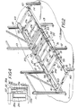
- Fig. 1 illustrates a push-in flow rack 10 having load transfer apparatus 20 embodying the present invention.
- the illustrated push-in flow rack comprises a series of pairs of uprights 11, 12, 13, 14 extending from front to rear and mounting a pair of L-shaped rails 15, 16 (Fig. 3) in horizontally spaced inclined relation.
- loads are shown three deep in the lowermost bay, two deep in the next higher bay, and one deep in the uppermost bay.
- the illustrated rack is termed a three load position push-in flow rack. While three tiers, or bays, are provided for supporting loads three deep at three levels in the illustrated rack, it should be understood that the present invention has applicability to push-in flow racks with greater or fewer bays of greater or lesser depths.
- the first load position is located adjacent to the front 10a of the rack 10.
- the second load position is located inwardly adjacent thereto.
- the third load position is located adjacent to the rear 10b of the rack 10.
- the push-in flow rack may store loads, either on pallets or slip sheets, at various depths in the bays and at various heights in the rack. However, when only one or two loads are in a rack, they will assume the positions illustrated in the uppermost and second highest bays in Fig. 1, respectively.
- the present invention comprises compact load transfer, or transport, apparatus 20 which is capable of accepting multiple loads sequentially at the front of the rack for loading, of transferring them in the rack for storage, and of delivering them sequentially to the front of the rack for unloading.
- the load transfer apparatus 20 comprises an elongated carriage 21 adapted to reciprocate, or ride back and forth, on the rails 15, 16, and a load support 22 adapted to reciprocate, or ride back and forth, relative to the carriage 21.
- the carriage 21 has a length corresponding to two load, or pallet, positions
- the load support 22 has a length corresponding to only one load position.
- the carriage 21 could support two standard size (1220 mm x 1016 mm - 48 inches x 40 inches) pallets end-to-end from front to rear thereon, and the load support 22 could support one pallet.
- the carriage 21 comprises a pair of elongated frame members 24, 25 overlying the rails 15, 16, respectively and a series of transverse connecting members 26, 27, 28 extending in spaced relation between the front and the rear ends 21 a and 21 b, respectively of the carriage 21.
- the carriage 21 has a widthwise dimension sufficient to enable it to support a standard size pallet widthwise and to fit within the upstanding flanges of the L-shaped rails 15, 16 with a clearance between the sides of the frame members 24, 25 and the rails 15, 16.
- first rotatable means are provided on the rails.
- a lower series of wheels are mounted in spaced relation to each frame member for rolling on the horizontal flanges of the rails, such as the lower series of wheels 30, 31, 32, 33 mounted to the frame member 24 for rolling on the horizontal flange 15b of the rail 15.
- the lower wheels 30-33 are sized and their axles located so that their peripheral edges, such as the edge 31', project outboard of the frame members for engaging the fillet 15' connecting the vertical and horizontal flanges 15a and 15b, respectively, of the rail 15. This aids in centering the carriage 21 on the rails 15 and 16 as the carriage moves back and forth in the rack.
- the wheels are provided at equally-spaced intervals, such as 457,2 mm 18 inch) centers, along the length of each carriage frame member to distribute loads on the rails in a desirable manner. It should be apparent, however, that the number of wheels can vary, depending on load.
- front and rear stop means are provided adjacent the front 10a and rear 10b of the rack 10.
- the front stop means comprises a pair of plates 40, 41 either welded or bolted transversely across the front ends of the rails 15, 16, respectively
- the rear stop means comprise a like pair of plates 42, 43 similarly either welded or bolted acros the rear ends of the rails 15, 16, respectively.
- the front stops 40, 41 cooperate with the carriage 21 to limit forward movement of the carriage 21 in the rack
- the rear stops 42, 43 likewise limit rearward movement of the carriage 21 therein.
- the load support 22 overlies only a portion of the carriage 21 and is mounted for back and forth movement relative to the carriage 21.
- the load support 22 is dimensioned lengthwise and widthwise to accept a single load, such as a pallet of conventional size.
- the carriage 21 is exposed for about half its two loads, or pallet, length.
- the load support 22 comprises a pair of elongated runners 35, 36 connected together widthwise by means of a series of stringers 37, 38, 39 providing a deck.
- each runner such as the runner 35, is provided by an L-shaped angle member having a depending vertical flange 35a and an outtumed horizontal flange 35b.
- the vertical flange 35a extends along the outer side of the carriage frame member 24, and the horizontal flange 35b is adapted to overlie the upper edge of the upstanding flange 15a of the rail member 15.
- second rotatable means is provided between the carriage 21 and the load support 22.
- an upper series of wheels are mounted on each of the carriage frame members at spaced locations along their lengths.
- the wheels 50-53 in the upper series are located sufficiently closely, i. e. on about 228,6 mm (9 inch) to 304,8 mm (12 inch) centers, as to enable at least a pair of wheels on each side of the carriage, such as the wheels 52, 53, to engage the load support 22 as it moves relative to the carriage 21.
- the upper series of wheels such as the wheels 50, 51, 52 and 53, are sized and their axles located so that their peripheries project upwardly above the frame members 24 and 25 to engage the horizontal flanges of the load support runners and to space the deck stringers 37-39 from the carriage 21.
- the downtumed flange 35a of the load support runner 35 engages between the insides of the wheels 50-53 in the upper series and the outer side of the frame member 24 to maintain the load support 22 laterally engaged with the carriage 21 as they move relative to one another.
- the wheels 50-53 preferably have edges which interact with the fillet 35' connecting the vertical and horizontal flanges 35a and 35b of the load support runner 35 to aid in guiding the load support 22 as it moves back and forth.
- the wheels 50-53 in the upper series have inside surfaces located slightly closer to the frame member 24 than the insides of the lower wheels to ensure smooth movement of the load support 22 relative to the carriage 21, particularly during loading of the second load onto the carriage 21 as will be discussed.
- the coupling means includes abutment means at both the front and rear of the carriage 21 to limit movement of the load support 22 in opposite directions thereon.
- the front abutment means includes a pair of abutment plates 55, 56 which project upwarly above the carriage frame members 24 and 25 into the path of movement of the load support runners 35, 36 respectively.
- the front abutment plates 55, 56 may be welded or bolted to the front ends of the carriage frame members 24, 25 respectively at the front end 21a of the carriage 21, and in like manner, a pair of rear abutment plates 57, 58 are mounted to the rear end 21 b of the carriage 21. It is the rear abutment plates 57, 58 which couple the carriage 21 and load support 22 for movement rearwardly in unison in the rack 10.
- the braking means includes detents provided by a pair of carriage bolts, 60, 61 such as the bolt 60 extending through the lower flange of the rail 16.
- the carriage bolts 60, 61 are located with their heads on top of the rail flanges.
- the detent bolts 60, 61 are located less than about 50,8 mm (two inches) behind the lower front wheels of the carriage 21 when it is engaged with the front rail stops 40 and 41.
- the bolts 60, 61 engage behind the front wheels in the lower series of carriage wheels to releasably retain the carriage 21 in its forwardly located position during placement of the first two loads in the rack.
- the detents are, however, sufficiently small as to enable the carriage 21 to be pushed rearwardly therepast in the course of placing the third load in the rack.
- the load transfer apparatus of the present invention is compact. As best seen in Fig. 3, when engaged, the carriage 21 and load support 22 present a relatively low profile, having a combined thickness only slightly greater than the vertical extent of the rails. As a result, the present inven- . tion minimizes the space required for the load transfer apparatus and thereby maximizes the space between tiers to provide a spatially efficient storage system.
- the carriage 21 will be located on the rails 15 and 16 with its forward abutment plates 55 and 56 engaged with the front stop plates 40 and 41 on the rails.
- the load support 22 will be located on the carriage 21 with the front edges of its runners 35 and 36 engaged with the abutment plates 55 and 56 at the front of the carriage 21.
- the load support 22 will overlie the front half of the carriage 21, the rear half of which will be exposed.
- a forklift truck or crane operator places a first load on the load support 22, such as in the manner in which the load L 1 is illustrated in the uppermost level in Fig. 1.
- the operator positions the second load, or pallet on which it is supported, in endwise engagement with the front deck stringer 37 of the load support 22 and pushes the second load L 2 into the bay.
- the operator pushes the second load L 2 deeper into the bay, it pushes the loated load support 22 rearwardly ahead of it relative to the carriage 21 until the load support 22 engages the rear abutment plates 57 and 58 on the carriage 21, whereupon movement of the load support 22 is arrested, and the load support 22 is coupled to the carriage 21.
- the detents 60, 61 ensure that the carriage 21 remains stationary as the load support 22 moves relative to the carriage 21.
- the front portion of the carriage 21 is exposed so that the operator can lower the second load L 2 on the front portion of the carriage 21, thereby causing two loads to be stored in the rack 10 such as in the manner the loads L 1 and L 2 are illustrated in the second highest bay in Fig. 1.
- the rack 10 is unloaded at a controlled rate by reversing the aforementioned loading procedure. For instance, after the third load has been lifted from the rails 15, 16, the forklift or crane operator can control the speed with which the carriage 21 rolls down the rails 15, 16 by maintaining the third and second loads engaged edgewise as he backs away from the rack 10. In like manner, when the second load is lifted from its position on the front of the carriage 21, the first load on the load support can be rolled forwardly at a controlled speed until the front edges of the load support runners 35, 36 engage the front abutment plates 40, 41 on the carriage 21. Thus, the entire load transfer apparatus is unloaded and automatically repositioned at the front of the rack for reloading.
- the load transfer apparatus 20 enables loads to be supported three deep in a three load position storage rack.
- modified load transfer apparatus is provided.
- the load transfer apparatus 120 is mounted in a rack 110 on a pair of inclined rails 115, like the rails 15, 16 extending from front to rear in the rack 110.
- the load transfer apparatus 120 comprises an elongated carriage 121, like in construction to the carriage 21 described heretofore, a load support 122 like in construction to the load support 22 described heretofore, and a load platform 123 like in construction to the load support 122.
- the carriage 121 is elongated and extends through at least three load positions in the rack 110.
- the load support 122 is similarly elongated and extends through two load positions.
- the load platform 123 extends through but a single load position in the rack 110.
- the carriage 121 is mounted for reciprocation in the rack 110 by a series of wheels, such as the wheel 131 illustrated in Fig. 6, arranged with like wheels such as in the manner illustrated in Fig. 2.
- the load support 122 is mounted for reciprocation relative to the carriage 131 by a series of wheels, such as the wheel 150, also arranged with like wheels such as in the manner illustrated in Fig. 2.
- An abutment or coupling plate 157 is mounted at the rear end of the carriage 121 for the purpose of coupling the load support 122 with the carriage 121 in the manner described heretofore. Except for their lengths, the carriage 121 and load support 122 are like in construction to the carriage 21 and load support 22 described heretofore with respect to the embodiment of Figs. 1-4.
- the load platform 170 overlies the load support 122 and is mounted for reciprocation relative to the load support 122.
- a series of wheels such as the wheel 171 are mounted to the load support 122 on opposite sides thereof for engaging runners 172 which extend lengthwise along the underside of the load platform 170 in much the same manner in which the runner 35 is mounted to the load support in the embodiment of Figs. 1-4.
- a rear abutment plate 175 is mounted at the rear end of the load support 122 for engaging the load platform 170 in much the same manner and for the same purpose as the rear abutment plate 157 is mounted to the carriage 121 for engaging the load support 122.
- the load platform 170 overlies one load position of the load support 122 which, in turn, overlies two load positions of the carriage 121.
- the load platform 170, the load support 122 and the carriage 121 are arranged in the manner illustrated in Fig. 6 when a single load L 1 is in the rack 110.
- the first load L 1 is displaced rearwardly (rightward in Fig. 5) until the rear end of the load platform 170 engages the abutment plate 175 on the load support 122, whereupon the load support 122 and load platform 170 are coupled and the front portion of the load support 122 is exposed for accepting a second load.
- a third load is inserted in the rack 110, it engages the front end of the load support 122 and pushes it rearwardly until its rear end engages the rear abutment plate 157 of the carriage 121 to couple the carriage 121 to the load support 122 and to expose the front portion of the carriage 121 for accepting the third load.
- a load transfer system 220 is provided for a storage rack having five tandem load positions.
- the storage rack 210 comprises a series of uprights to which are mounted a first pair of rails 215a and a second pair of rails 215b.
- the first pair of rails 215a are inclined and extend through three load positions in the rack 210.
- the second pair of rails 215b extend alongside the first pair of rails 215a at a slightly higher level and through five load positions in the rack 210.
- the rails in each pair are preferably L-shaped and are arranged symmetrically in an upwardly and outwardly offset relation to one another.
- the load transfer apparatus 220 associated with the rack 210 comprises a carriage 221, like in construction to the carriage 21, and a load support 222 like in construction to the load support 22.
- the carriage 221 and load support 222 function in the same manner as the carriage 21 and load support 22 described heretofore with respect to the embodiment of Figs. 1-4.
- a second carriage 280 is mounted for reciprocation on the second pair of rails 215b.
- the second carriage 280 is somewhat similar in construction to the first carriage 221, except that its longitudinal frame member is provided by an angle member arranged in the manner shown in order to conserve space.
- the second carriage 280 has a lower and an upper series of wheels, such as the wheels 231 and 250.
- the wheel 231 is adapted to ride on the rail 215b in the same manner that the wheel 31 is adapted to ride on the rail 15 in the embodiment of Figs. 1-4.
- a second load support 281 is mounted to the second carriage 280 for back and forth movement relative thereto.
- the second load support 281 is like in construction to the load support 22 described heretofore, being adapted to ride on wheels in the upper series, such as the wheel 250, in the same manner as the load support 22 is adapted to ride on the upper wheels 50-53 in the embodiment illustrated in Fig. 2.
- a coupling or abutment plate 282 is mounted at the rear end of the second carriage 280 for releasably engaging the second load support 281 after it has been displaced rearwardly a predetermined distance with respect to the second carriage 280 to expose its front portion for accepting a load.
- first and second carriages 221 and 280, and the first and second load supports 222 and 281 are arranged adjacent the front of the rack 210 in the manner illustrated in Fig. 8 when a first load L 1 is placed in the rack 210.
- the first load L 1 is displaced rightward until the rear end of the second load support 281 engages the rear abutment plate 282 of the second carriage 280. This exposes the front portion of the second carriage 280 and permits the second load to be deposited thereon.
- the load transfer apparatus continues to displace the first load L, further rearwardly in the rack until it assumes the position indicated by the dotted lines in Fig. 7.
- the first load L is in this position, the front portion of the rails 215a adjacent the front end of the rack 210 are exposed to receive the fifth load in much the same manner that the front portions of the rails are exposed to receive the third load in the embodiment of Figs. 1-4.
- a push-in flow rack having the capability of supporting and transferring five loads is provided.
- the present invention now provides a push-in flow rack having improved load transfer apparatus which is capable of accepting a plurality of loads one-by-one at the front of the rack, transferring the loads therein, supporting the loads in tandem in several load positions, and delivering the loads one-by-one for unloading from the front of the rack.
- the load transfer apparatus has a relatively low vertical profile, thereby making efficient utilization of vertical space in the rack. Because the load transfer apparatus is of relatively simple design, it can be manufactured readily, and it is rugged, durable and relatively maintenance free. Moreover, the load transfer apparatus of the present invention is capable of being installed in existing push-in flow rack systems having L-shaped inclined rails.
Landscapes
- Engineering & Computer Science (AREA)
- Mechanical Engineering (AREA)
- Warehouses Or Storage Devices (AREA)
- Special Conveying (AREA)
- Feeding, Discharge, Calcimining, Fusing, And Gas-Generation Devices (AREA)
- Manipulator (AREA)
- Specific Conveyance Elements (AREA)
Priority Applications (1)
| Application Number | Priority Date | Filing Date | Title |
|---|---|---|---|
| AT86901629T ATE44271T1 (de) | 1985-02-22 | 1986-02-19 | Lastuebergabeeinrichtung fuer einschubregale. |
Applications Claiming Priority (2)
| Application Number | Priority Date | Filing Date | Title |
|---|---|---|---|
| US704286 | 1985-02-22 | ||
| US06/704,286 US4687404A (en) | 1985-02-22 | 1985-02-22 | Load transfer apparatus for push-in flow racks |
Publications (3)
| Publication Number | Publication Date |
|---|---|
| EP0214228A1 EP0214228A1 (en) | 1987-03-18 |
| EP0214228A4 EP0214228A4 (en) | 1987-07-06 |
| EP0214228B1 true EP0214228B1 (en) | 1989-06-28 |
Family
ID=24828844
Family Applications (1)
| Application Number | Title | Priority Date | Filing Date |
|---|---|---|---|
| EP86901629A Expired EP0214228B1 (en) | 1985-02-22 | 1986-02-19 | Load transfer apparatus for push-in flow racks |
Country Status (11)
| Country | Link |
|---|---|
| US (1) | US4687404A (mo) |
| EP (1) | EP0214228B1 (mo) |
| JP (1) | JPS62502040A (mo) |
| KR (1) | KR950003593B1 (mo) |
| AT (1) | ATE44271T1 (mo) |
| AU (1) | AU574314B2 (mo) |
| BR (1) | BR8605478A (mo) |
| CA (1) | CA1249980A (mo) |
| DE (1) | DE3664130D1 (mo) |
| WO (1) | WO1986004881A1 (mo) |
| ZA (1) | ZA86657B (mo) |
Cited By (1)
| Publication number | Priority date | Publication date | Assignee | Title |
|---|---|---|---|---|
| DE202004002931U1 (de) * | 2003-04-28 | 2004-09-02 | Grob-Werke Burkhart Grob E.K. | Vorrichtung für das Transportieren von Gütern |
Families Citing this family (49)
| Publication number | Priority date | Publication date | Assignee | Title |
|---|---|---|---|---|
| FI75542C (fi) * | 1986-02-27 | 1989-09-11 | Ahlstroem Valmet | Anordning foer foerflyttning av tambourvals till en pappers- eller kartongmaskins rullmaskin. |
| US4773546A (en) * | 1987-05-21 | 1988-09-27 | Konstant Products, Inc. | Pallet rack |
| US4988251A (en) * | 1987-10-21 | 1991-01-29 | Interlake, Inc. | Multiple load storage rack structure |
| US4936738A (en) * | 1988-04-26 | 1990-06-26 | Food Plant Engineering, Inc. | Alternating push back selective rack storage system |
| US4915240A (en) * | 1989-02-16 | 1990-04-10 | Konstant Products, Inc. | Multiple pallet rack |
| US4949852A (en) * | 1989-09-13 | 1990-08-21 | Frazier Industrial Company | Storage rack systems |
| US4982851A (en) * | 1990-02-07 | 1991-01-08 | Konstant Anthony N | Supported pallet rack |
| US5141118A (en) * | 1990-11-20 | 1992-08-25 | Gay Kenneth F | Multiple carriage based rack assembly |
| US5180069A (en) * | 1990-12-06 | 1993-01-19 | Advance Storage Products | Four-deep push-back warehouse storage rack system |
| US5080241A (en) * | 1991-02-08 | 1992-01-14 | Konstant Anthony N | Rolling rack for skids and the like |
| US5137159A (en) * | 1991-02-15 | 1992-08-11 | The Interlake Companies, Inc. | Push-back rack |
| US5228823A (en) * | 1991-05-06 | 1993-07-20 | Crook Thomas J | Mobile racking system |
| AU659181B2 (en) * | 1991-08-15 | 1995-05-11 | Thomas James Crook | Vehicle racking system |
| US5178288A (en) * | 1991-11-18 | 1993-01-12 | Interroll Canada Limited | Push back pallet rack |
| US5170896A (en) * | 1992-03-16 | 1992-12-15 | Konstant Products, Inc. | Pallet return pallet rack system |
| US5312004A (en) * | 1992-04-30 | 1994-05-17 | John V. R. Krummell | Push-back retrofit system for a storage rack assembly |
| US5474412A (en) * | 1993-02-05 | 1995-12-12 | Pfeiffer; Harold | Flow rack system |
| JP3386507B2 (ja) * | 1993-03-30 | 2003-03-17 | 富士通株式会社 | 情報処理機器の立体設置装置 |
| CA2098433C (en) * | 1993-06-15 | 1995-04-04 | Todd Scott | Pallet storage system |
| US5415300A (en) * | 1993-11-05 | 1995-05-16 | Krummell; John V. R. | Push-back cart storage system |
| US5419444A (en) * | 1993-11-12 | 1995-05-30 | Inca Metal Products Corporation | Low profile push-back rack assembly |
| US5524776A (en) * | 1993-12-17 | 1996-06-11 | Hall; Roger W. | Low inclination push back storage rack system |
| US5476180A (en) * | 1994-05-03 | 1995-12-19 | Konstant Products, Inc. | Cart return device |
| US5482422A (en) * | 1994-08-15 | 1996-01-09 | Hammond; Theodore A. | Push back storage rack |
| US6112915A (en) * | 1995-02-14 | 2000-09-05 | Lewis; Lyman F. | Push-back storage rack |
| US5797503A (en) * | 1995-04-21 | 1998-08-25 | Metro Industries, Inc. | Modular storage system with an active storage level feature |
| US5944202A (en) * | 1997-11-18 | 1999-08-31 | Wylie; John F. | Material handling pushback |
| US6129223A (en) * | 1998-05-28 | 2000-10-10 | Krummell, Jr.; John V. R. | Push-back cart storage system |
| US6267258B1 (en) | 1999-05-07 | 2001-07-31 | Gilmour, Inc. | Gravity feed pull out shelf with rear storage area and associated method for displaying and storing a product |
| US6158943A (en) * | 1999-06-28 | 2000-12-12 | Sullivan; Chad D. | Pushback storage system |
| CA2336502A1 (en) * | 2000-07-12 | 2002-01-12 | Ridg-U-Rak, Inc. | Push back storage rack system |
| DE102005060220B3 (de) * | 2005-12-16 | 2006-10-12 | Kone Corp. | Aufnahme- und Transporteinrichtung |
| US7748546B2 (en) * | 2006-01-27 | 2010-07-06 | Konstant Products, Inc. | Reinforced and bolted rack truss |
| US7753220B2 (en) * | 2006-01-27 | 2010-07-13 | Konstant Products, Inc. | Reinforced and bolted rack truss |
| US7780019B2 (en) * | 2006-06-27 | 2010-08-24 | Konstant Products, Inc. | Cantilever pallet cart |
| US20100054906A1 (en) * | 2006-07-11 | 2010-03-04 | J&D Global, Ltd. | Racking system and method of storing palletized items |
| US20080169737A1 (en) * | 2007-01-16 | 2008-07-17 | Min-Dy Shen | Adjustable Pull-Out Frame Structure |
| US7770903B2 (en) * | 2007-02-26 | 2010-08-10 | Konstant Products, Inc. | Drawer type storage cart |
| US20110139733A1 (en) * | 2009-06-15 | 2011-06-16 | J&D Global., Ltd. | Rack system |
| US8739985B2 (en) * | 2010-12-15 | 2014-06-03 | J. C. M. Industries, Inc. | Push-back cart storage system with a top cart rolling on top of push-back rails |
| JP5886116B2 (ja) * | 2012-04-19 | 2016-03-16 | 住友理工株式会社 | 自動倉庫のラック |
| US10106293B2 (en) | 2014-11-03 | 2018-10-23 | Fred E. Clark | Pallet for the storage and transportation of articles |
| US11084622B2 (en) * | 2014-12-09 | 2021-08-10 | Swisslog Logistics, Inc. | Structure for automated pallet storage and retrieval |
| SG11201703153SA (en) | 2014-12-24 | 2017-05-30 | Veltek Associates Inc | Cart with removable wheel base |
| US11555576B2 (en) * | 2014-12-24 | 2023-01-17 | Veltek Associates, Inc. | Stationary transfer platform and cleaning device for supply transport device |
| USD809730S1 (en) | 2015-12-22 | 2018-02-06 | Veltek Associates, Inc. | Cart |
| DE202016106276U1 (de) * | 2016-11-10 | 2016-12-09 | Bito-Lagertechnik Bittmann Gmbh | Shuttlelager |
| NZ801144A (en) * | 2017-06-29 | 2025-11-28 | Veltek Ass Inc | Stationary transfer platform and cleaning device for supply transport device |
| KR102217127B1 (ko) | 2020-06-26 | 2021-02-18 | (주)에이스메카텍 | 플로우랙용 전기식 세퍼레이터 시스템 |
Citations (1)
| Publication number | Priority date | Publication date | Assignee | Title |
|---|---|---|---|---|
| US4136783A (en) * | 1977-02-28 | 1979-01-30 | Masashi Karashima | Showcase equipment |
Family Cites Families (11)
| Publication number | Priority date | Publication date | Assignee | Title |
|---|---|---|---|---|
| US3038613A (en) * | 1957-08-26 | 1962-06-12 | Rack Specialists Inc | Storage rack structure |
| DE1141231B (de) * | 1961-01-25 | 1962-12-13 | Continental Gummi Werke Ag | Lagerguttraeger fuer Durchlaufregale |
| US3179258A (en) * | 1963-03-15 | 1965-04-20 | Stoneham Associates Inc | Storage device |
| US3399784A (en) * | 1966-08-01 | 1968-09-03 | Ardco Inc | Shelving units with rolling shelves |
| US3465894A (en) * | 1968-02-15 | 1969-09-09 | John C Setecka | Portable food service device for tables and the like |
| AT326047B (de) * | 1973-09-06 | 1975-11-25 | Haldimann Consultants | Durchlaufregallager-anlage |
| GB1558141A (en) * | 1977-01-07 | 1979-12-19 | Lansing Bagnall Ltd | Storage racks for warehouses and the like |
| DE2829325C3 (de) * | 1978-07-04 | 1981-10-22 | Döring, Erich, 9442 Berneck, Sankt Gallen | Hochregal für Platten |
| US4234069A (en) * | 1979-09-07 | 1980-11-18 | Variable Control Systems, Inc. | Vehicle speed control apparatus |
| US4462500A (en) * | 1982-05-19 | 1984-07-31 | Speedrack, Inc. | Multiple location storage bays |
| US4613270A (en) * | 1983-11-17 | 1986-09-23 | Speedrack, Inc. | Storage rack having bays with multiple rails and interlocking trolleys |
-
1985
- 1985-02-22 US US06/704,286 patent/US4687404A/en not_active Expired - Lifetime
-
1986
- 1986-01-23 CA CA000500174A patent/CA1249980A/en not_active Expired
- 1986-01-29 ZA ZA86657A patent/ZA86657B/xx unknown
- 1986-02-19 BR BR8605478A patent/BR8605478A/pt not_active IP Right Cessation
- 1986-02-19 AT AT86901629T patent/ATE44271T1/de not_active IP Right Cessation
- 1986-02-19 JP JP61501249A patent/JPS62502040A/ja active Granted
- 1986-02-19 KR KR1019860700735A patent/KR950003593B1/ko not_active Expired - Lifetime
- 1986-02-19 EP EP86901629A patent/EP0214228B1/en not_active Expired
- 1986-02-19 WO PCT/US1986/000316 patent/WO1986004881A1/en not_active Ceased
- 1986-02-19 DE DE8686901629T patent/DE3664130D1/de not_active Expired
- 1986-02-19 AU AU55129/86A patent/AU574314B2/en not_active Ceased
Patent Citations (1)
| Publication number | Priority date | Publication date | Assignee | Title |
|---|---|---|---|---|
| US4136783A (en) * | 1977-02-28 | 1979-01-30 | Masashi Karashima | Showcase equipment |
Cited By (1)
| Publication number | Priority date | Publication date | Assignee | Title |
|---|---|---|---|---|
| DE202004002931U1 (de) * | 2003-04-28 | 2004-09-02 | Grob-Werke Burkhart Grob E.K. | Vorrichtung für das Transportieren von Gütern |
Also Published As
| Publication number | Publication date |
|---|---|
| WO1986004881A1 (en) | 1986-08-28 |
| ATE44271T1 (de) | 1989-07-15 |
| AU574314B2 (en) | 1988-06-30 |
| BR8605478A (pt) | 1987-04-22 |
| KR950003593B1 (ko) | 1995-04-14 |
| CA1249980A (en) | 1989-02-14 |
| KR870700058A (ko) | 1987-02-28 |
| AU5512986A (en) | 1986-09-10 |
| ZA86657B (en) | 1986-09-24 |
| US4687404A (en) | 1987-08-18 |
| EP0214228A4 (en) | 1987-07-06 |
| DE3664130D1 (en) | 1989-08-03 |
| JPH0559002B2 (mo) | 1993-08-30 |
| JPS62502040A (ja) | 1987-08-13 |
| EP0214228A1 (en) | 1987-03-18 |
Similar Documents
| Publication | Publication Date | Title |
|---|---|---|
| EP0214228B1 (en) | Load transfer apparatus for push-in flow racks | |
| EP0153040B1 (en) | Storage rack having bays with multiple rails and interlocking trolleys | |
| EP0109440B1 (en) | Multiple location storage bays | |
| GB2024179A (en) | Pallet rack | |
| US4773546A (en) | Pallet rack | |
| US4982851A (en) | Supported pallet rack | |
| EP0726724B1 (en) | Push-back cart storage system | |
| US4915240A (en) | Multiple pallet rack | |
| US5678972A (en) | Facility for the space-saving parking of motor vehicles | |
| US5419444A (en) | Low profile push-back rack assembly | |
| US5141118A (en) | Multiple carriage based rack assembly | |
| US5476180A (en) | Cart return device | |
| CA2098433C (en) | Pallet storage system | |
| US4597339A (en) | Pallet | |
| JPH01197212A (ja) | パレットを格納するための格納装置 | |
| CA2076880C (en) | Pallet return pallet rack system | |
| US5524776A (en) | Low inclination push back storage rack system | |
| US5178288A (en) | Push back pallet rack | |
| EP0164387B1 (en) | A storage and handling installation for palletised goods | |
| CA2484882A1 (en) | Pushback cart storage system | |
| CA2312294C (en) | Pushback storage system | |
| US3432046A (en) | Transfer means for a load carrier in a storage system | |
| US5848713A (en) | Pallet return storage system | |
| CA2151315C (en) | Cart return system | |
| WO2005095235A1 (en) | Compact pushback storing system for pallets |
Legal Events
| Date | Code | Title | Description |
|---|---|---|---|
| PUAI | Public reference made under article 153(3) epc to a published international application that has entered the european phase |
Free format text: ORIGINAL CODE: 0009012 |
|
| 17P | Request for examination filed |
Effective date: 19861101 |
|
| AK | Designated contracting states |
Kind code of ref document: A1 Designated state(s): AT BE CH DE FR GB IT LI LU NL SE |
|
| A4 | Supplementary search report drawn up and despatched |
Effective date: 19870706 |
|
| 17Q | First examination report despatched |
Effective date: 19880914 |
|
| GRAA | (expected) grant |
Free format text: ORIGINAL CODE: 0009210 |
|
| AK | Designated contracting states |
Kind code of ref document: B1 Designated state(s): AT BE CH DE FR GB IT LI LU NL SE |
|
| PG25 | Lapsed in a contracting state [announced via postgrant information from national office to epo] |
Ref country code: LI Effective date: 19890628 Ref country code: CH Effective date: 19890628 Ref country code: BE Effective date: 19890628 Ref country code: AT Effective date: 19890628 |
|
| REF | Corresponds to: |
Ref document number: 44271 Country of ref document: AT Date of ref document: 19890715 Kind code of ref document: T |
|
| REF | Corresponds to: |
Ref document number: 3664130 Country of ref document: DE Date of ref document: 19890803 |
|
| ITF | It: translation for a ep patent filed | ||
| REG | Reference to a national code |
Ref country code: CH Ref legal event code: PL |
|
| ET | Fr: translation filed | ||
| PG25 | Lapsed in a contracting state [announced via postgrant information from national office to epo] |
Ref country code: LU Free format text: LAPSE BECAUSE OF NON-PAYMENT OF DUE FEES Effective date: 19900228 |
|
| PLBE | No opposition filed within time limit |
Free format text: ORIGINAL CODE: 0009261 |
|
| STAA | Information on the status of an ep patent application or granted ep patent |
Free format text: STATUS: NO OPPOSITION FILED WITHIN TIME LIMIT |
|
| 26N | No opposition filed | ||
| ITTA | It: last paid annual fee | ||
| PGFP | Annual fee paid to national office [announced via postgrant information from national office to epo] |
Ref country code: NL Payment date: 19930228 Year of fee payment: 8 |
|
| PGFP | Annual fee paid to national office [announced via postgrant information from national office to epo] |
Ref country code: FR Payment date: 19930311 Year of fee payment: 8 |
|
| PGFP | Annual fee paid to national office [announced via postgrant information from national office to epo] |
Ref country code: SE Payment date: 19930315 Year of fee payment: 8 |
|
| PGFP | Annual fee paid to national office [announced via postgrant information from national office to epo] |
Ref country code: DE Payment date: 19930317 Year of fee payment: 8 |
|
| PGFP | Annual fee paid to national office [announced via postgrant information from national office to epo] |
Ref country code: GB Payment date: 19930325 Year of fee payment: 8 |
|
| PG25 | Lapsed in a contracting state [announced via postgrant information from national office to epo] |
Ref country code: GB Effective date: 19940219 |
|
| PG25 | Lapsed in a contracting state [announced via postgrant information from national office to epo] |
Ref country code: SE Effective date: 19940220 |
|
| PG25 | Lapsed in a contracting state [announced via postgrant information from national office to epo] |
Ref country code: NL Effective date: 19940901 |
|
| NLV4 | Nl: lapsed or anulled due to non-payment of the annual fee | ||
| GBPC | Gb: european patent ceased through non-payment of renewal fee |
Effective date: 19940219 |
|
| PG25 | Lapsed in a contracting state [announced via postgrant information from national office to epo] |
Ref country code: FR Effective date: 19941031 |
|
| PG25 | Lapsed in a contracting state [announced via postgrant information from national office to epo] |
Ref country code: DE Effective date: 19941101 |
|
| REG | Reference to a national code |
Ref country code: FR Ref legal event code: ST |
|
| EUG | Se: european patent has lapsed |
Ref document number: 86901629.5 Effective date: 19940910 |
|
| PG25 | Lapsed in a contracting state [announced via postgrant information from national office to epo] |
Ref country code: IT Free format text: LAPSE BECAUSE OF NON-PAYMENT OF DUE FEES;WARNING: LAPSES OF ITALIAN PATENTS WITH EFFECTIVE DATE BEFORE 2007 MAY HAVE OCCURRED AT ANY TIME BEFORE 2007. THE CORRECT EFFECTIVE DATE MAY BE DIFFERENT FROM THE ONE RECORDED. Effective date: 20050219 |