EP0213453A2 - Verminderung des Rauschens während des Prüfens von integrierten Schaltungschips - Google Patents
Verminderung des Rauschens während des Prüfens von integrierten Schaltungschips Download PDFInfo
- Publication number
- EP0213453A2 EP0213453A2 EP86110981A EP86110981A EP0213453A2 EP 0213453 A2 EP0213453 A2 EP 0213453A2 EP 86110981 A EP86110981 A EP 86110981A EP 86110981 A EP86110981 A EP 86110981A EP 0213453 A2 EP0213453 A2 EP 0213453A2
- Authority
- EP
- European Patent Office
- Prior art keywords
- input
- chip
- driver
- tester
- output
- Prior art date
- Legal status (The legal status is an assumption and is not a legal conclusion. Google has not performed a legal analysis and makes no representation as to the accuracy of the status listed.)
- Granted
Links
Images

Classifications
-
- G—PHYSICS
- G01—MEASURING; TESTING
- G01R—MEASURING ELECTRIC VARIABLES; MEASURING MAGNETIC VARIABLES
- G01R31/00—Arrangements for testing electric properties; Arrangements for locating electric faults; Arrangements for electrical testing characterised by what is being tested not provided for elsewhere
- G01R31/28—Testing of electronic circuits, e.g. by signal tracer
- G01R31/316—Testing of analog circuits
-
- G—PHYSICS
- G01—MEASURING; TESTING
- G01R—MEASURING ELECTRIC VARIABLES; MEASURING MAGNETIC VARIABLES
- G01R31/00—Arrangements for testing electric properties; Arrangements for locating electric faults; Arrangements for electrical testing characterised by what is being tested not provided for elsewhere
- G01R31/28—Testing of electronic circuits, e.g. by signal tracer
- G01R31/317—Testing of digital circuits
- G01R31/3181—Functional testing
- G01R31/319—Tester hardware, i.e. output processing circuits
- G01R31/31917—Stimuli generation or application of test patterns to the device under test [DUT]
- G01R31/31924—Voltage or current aspects, e.g. driver, receiver
-
- G—PHYSICS
- G01—MEASURING; TESTING
- G01R—MEASURING ELECTRIC VARIABLES; MEASURING MAGNETIC VARIABLES
- G01R31/00—Arrangements for testing electric properties; Arrangements for locating electric faults; Arrangements for electrical testing characterised by what is being tested not provided for elsewhere
- G01R31/28—Testing of electronic circuits, e.g. by signal tracer
- G01R31/317—Testing of digital circuits
- G01R31/3181—Functional testing
- G01R31/319—Tester hardware, i.e. output processing circuits
- G01R31/3193—Tester hardware, i.e. output processing circuits with comparison between actual response and known fault free response
Definitions
- EP-A-132,522 published February 13, 1985, entitled “Oscillation Prevention During Testing of Integrated Circuit Logic Chips”.
- This invention relates to testing of integrated circuit logic chips and more particularly to excessive noise (Delta I) prevention during the testing thereof.
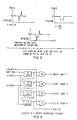
- delta I When many off chip drivers switch simultaneously a large change in power supply current results (delta I).
- This delta I current path flows from the driver output wire, through the driver, through the unbypassed inductance and resistance of the power supply distribution network, through the bypass capacitor and back to the tester ground.
- Voltage and current signals which change as a driver changes state also couple through mutual inductance and mutual capacitance into nearby I/O paths.
- Mutual inductance and mutual capacitance coupling may contribute, or solely result in false switching and test failures.
- the noise magnitude relates directly to the driver type (speed) and the number of drivers coupling noise into a nearby I/O path.
- the invention may be summarized as a driver sequencing network (DSN) on the integrated circuit device, or chip, to be tested which gives the tester (machine) control of the timing between the switching of groups of driver circuits so that more than a predetermined number of driver circuits concurrently switching state is precluded.
- the driver sequencing network is such that no one group of driver output pins can create enough delta I or coupled noise to cause a test failure.
- the driver sequencing network may be disabled to give full control of the driver outputs to the device being tested. In a normal application, i.e. the intended purpose or function of the device, the driver sequencing network is disabled.
- the function of the driver sequencing network is to control off chip driver switching during test. (An "off chip driver” is an output amplifier contained on the chip, to generate device output signals, also called off ship signals).
- FIG. 1 shows this delta I and its path from the driver output wire, through the driver, through the unbypassed inductance and resistance of the power supply distribution network, through the bypass capacitor and back to the tester ground.
- V MdI/dt
- I CdV/dt
- FIG. 4 shows an example of a driver sequencing network. Inputs labeled “+ Inhibit,” “Shift In,” “L1 Clock,” and “L2 Clock” are controlled by the tester. Outputs “+ Inhibit Group 1" through “+ Inhibit Group 4" continue on the chip as the inhibit control lines for the respective off chip driver groups.
- the driver sequencing network shown is on the chip.
- DSN driver sequencing network
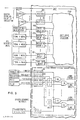
- FIG. 5 A preferred embodiment of the invention employing the driver sequence network can be seen in FIG. 5.
- the logic function internal to the chip is fed by a plurality of logical input receivers R5 through R54.
- the chip's logic function output is passed back to the tester through off chip drivers D2 through D1O2.
- Each driver D3 through D1O2 has at least one logic input and a driver inhibit input which, when active, blocks (inhibits) the logic state coming into the driver and forces the driver output to known or high impedance state.
- Driver D2 does not get inhibited in any circumstance.
- D2 is the commonly known shift register output of a Level Sensitive Scan Design (LSSD) register string.
- the LSSD register string is utilized in the chip logic function and enhances testability of that logic.
- FIG. 6 shows an example of a driver circuit with three logic inputs and an inhibit input
- FIG. 7 shows a corresponding logic diagram.
- All of the items listed above are fabricated on the chip and, except for the said driver inhibit inputs, are normal or conventional to a VLSI chip.
- a Driver Sequence Network To embody a Driver Sequence Network, additional receivers, drivers and logic is required.
- a representative DSN is shown enclosed within a broken line bearing the legend "Driver Sequencing Network" at the lower right of FIG. 6.
- the off chip drivers D3 through D1O2 are divided into ten groups of ten drivers each. Each group shares a common inhibit line so that there are ten separate group inhibit lines, one for each driver group. Again, D2 does not get inhibited because it provides the shift register output function.
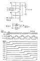
- the group inhibit lines may all be set to the inhibiting state simultaneously by the "+ Inhibit" control line or each group inhibit line may be brought up sequentially by using the "Sequence Scan In', "+L1 Clock', and “+L2 Clock' to shift a logical "1' through the ten shift register latches (L1 through L1O).
- the "+ Inhibit” line may allow all group inhibit lines to go to the enable state simultaneously, or each line may be enabled sequentially by shifting a logical "O' through the ten latches (See FIG. 8 for a timing diagram of the shift operation; the shifting of a logical "1' is shown).
- Driver D1 facilitates testing of the sequencing shift register of the DSN by providing a shift register output to the tester.
- test execution steps can be used to prevent too many off chip drivers from switching simultaneously.
Landscapes
- Engineering & Computer Science (AREA)
- General Engineering & Computer Science (AREA)
- Physics & Mathematics (AREA)
- General Physics & Mathematics (AREA)
- Tests Of Electronic Circuits (AREA)
- Testing Or Measuring Of Semiconductors Or The Like (AREA)
- Semiconductor Integrated Circuits (AREA)
Applications Claiming Priority (2)
| Application Number | Priority Date | Filing Date | Title |
|---|---|---|---|
| US06/771,928 US4644265A (en) | 1985-09-03 | 1985-09-03 | Noise reduction during testing of integrated circuit chips |
| US771928 | 1985-09-03 |
Publications (3)
| Publication Number | Publication Date |
|---|---|
| EP0213453A2 true EP0213453A2 (de) | 1987-03-11 |
| EP0213453A3 EP0213453A3 (en) | 1989-03-29 |
| EP0213453B1 EP0213453B1 (de) | 1992-10-21 |
Family
ID=25093363
Family Applications (1)
| Application Number | Title | Priority Date | Filing Date |
|---|---|---|---|
| EP86110981A Expired - Lifetime EP0213453B1 (de) | 1985-09-03 | 1986-08-08 | Verminderung des Rauschens während des Prüfens von integrierten Schaltungschips |
Country Status (4)
| Country | Link |
|---|---|
| US (1) | US4644265A (de) |
| EP (1) | EP0213453B1 (de) |
| JP (1) | JPH0762695B2 (de) |
| DE (1) | DE3686989T2 (de) |
Families Citing this family (11)
| Publication number | Priority date | Publication date | Assignee | Title |
|---|---|---|---|---|
| US5046048A (en) * | 1988-07-15 | 1991-09-03 | Kabushiki Kaisha Toshiba | Semiconductor integrated circuit including output buffer |
| US4973904A (en) * | 1988-12-12 | 1990-11-27 | Ncr Corporation | Test circuit and method |
| US5289118A (en) * | 1991-02-01 | 1994-02-22 | Data I/O Corporation | Programmer/tester with electronically switched bypass capacitor |
| US5142167A (en) * | 1991-05-01 | 1992-08-25 | International Business Machines Corporation | Encoding for simultaneous switching output noise reduction |
| US5463315A (en) * | 1993-06-15 | 1995-10-31 | Hewlett-Packard Company | Spike suppression for a tester circuit for integrated circuits |
| US5504423A (en) * | 1994-11-01 | 1996-04-02 | The Research Foundation Of State University Of New York | Method for modeling interactions in multilayered electronic packaging structures |
| US5477460A (en) * | 1994-12-21 | 1995-12-19 | International Business Machines Corporation | Early high level net based analysis of simultaneous switching |
| US5572736A (en) * | 1995-03-31 | 1996-11-05 | International Business Machines Corporation | Method and apparatus for reducing bus noise and power consumption |
| US5663966A (en) * | 1996-07-24 | 1997-09-02 | International Business Machines Corporation | System and method for minimizing simultaneous switching during scan-based testing |
| JP4652729B2 (ja) * | 2004-06-28 | 2011-03-16 | 富士通セミコンダクター株式会社 | 半導体装置 |
| US20080046789A1 (en) * | 2006-08-21 | 2008-02-21 | Igor Arsovski | Apparatus and method for testing memory devices and circuits in integrated circuits |
Family Cites Families (24)
| Publication number | Priority date | Publication date | Assignee | Title |
|---|---|---|---|---|
| US3599161A (en) * | 1969-04-03 | 1971-08-10 | Computer Test Corp | Computer controlled test system and method |
| US3694632A (en) * | 1969-12-31 | 1972-09-26 | Hawker Siddeley Dynamics Ltd | Automatic test equipment utilizing a matrix of digital differential analyzer integrators to generate interrogation signals |
| US3784910A (en) * | 1972-07-13 | 1974-01-08 | Teradyne Inc | Sequential addressing network testing system |
| US3789205A (en) * | 1972-09-28 | 1974-01-29 | Ibm | Method of testing mosfet planar boards |
| FR2330014A1 (fr) * | 1973-05-11 | 1977-05-27 | Ibm France | Procede de test de bloc de circuits logiques integres et blocs en faisant application |
| US3848188A (en) * | 1973-09-10 | 1974-11-12 | Probe Rite Inc | Multiplexer control system for a multi-array test probe assembly |
| US3873818A (en) * | 1973-10-29 | 1975-03-25 | Ibm | Electronic tester for testing devices having a high circuit density |
| US3961251A (en) * | 1974-12-20 | 1976-06-01 | International Business Machines Corporation | Testing embedded arrays |
| US3976940A (en) * | 1975-02-25 | 1976-08-24 | Fairchild Camera And Instrument Corporation | Testing circuit |
| US4066882A (en) * | 1976-08-16 | 1978-01-03 | Grumman Aerospace Corporation | Digital stimulus generating and response measuring means |
| US4070565A (en) * | 1976-08-18 | 1978-01-24 | Zehntel, Inc. | Programmable tester method and apparatus |
| US4125763A (en) * | 1977-07-15 | 1978-11-14 | Fluke Trendar Corporation | Automatic tester for microprocessor board |
| US4180203A (en) * | 1977-09-30 | 1979-12-25 | Westinghouse Electric Corp. | Programmable test point selector circuit |
| US4216539A (en) * | 1978-05-05 | 1980-08-05 | Zehntel, Inc. | In-circuit digital tester |
| DE2842750A1 (de) * | 1978-09-30 | 1980-04-10 | Ibm Deutschland | Verfahren und anordnung zur pruefung von durch monolithisch integrierten halbleiterschaltungen dargestellten sequentiellen schaltungen |
| US4348759A (en) * | 1979-12-17 | 1982-09-07 | International Business Machines Corporation | Automatic testing of complex semiconductor components with test equipment having less channels than those required by the component under test |
| US4334310A (en) * | 1980-06-23 | 1982-06-08 | International Business Machines Corporation | Noise suppressing bilevel data signal driver circuit arrangement |
| US4398106A (en) * | 1980-12-19 | 1983-08-09 | International Business Machines Corporation | On-chip Delta-I noise clamping circuit |
| US4494066A (en) * | 1981-07-02 | 1985-01-15 | International Business Machines Corporation | Method of electrically testing a packaging structure having n interconnected integrated circuit chips |
| US4504784A (en) * | 1981-07-02 | 1985-03-12 | International Business Machines Corporation | Method of electrically testing a packaging structure having N interconnected integrated circuit chips |
| US4441075A (en) * | 1981-07-02 | 1984-04-03 | International Business Machines Corporation | Circuit arrangement which permits the testing of each individual chip and interchip connection in a high density packaging structure having a plurality of interconnected chips, without any physical disconnection |
| US4551838A (en) * | 1983-06-20 | 1985-11-05 | At&T Bell Laboratories | Self-testing digital circuits |
| US4553049A (en) * | 1983-10-07 | 1985-11-12 | International Business Machines Corporation | Oscillation prevention during testing of integrated circuit logic chips |
| JPS60187871A (ja) * | 1984-03-07 | 1985-09-25 | Mitsubishi Electric Corp | 論理集積回路 |
-
1985
- 1985-09-03 US US06/771,928 patent/US4644265A/en not_active Expired - Fee Related
-
1986
- 1986-08-01 JP JP61180262A patent/JPH0762695B2/ja not_active Expired - Lifetime
- 1986-08-08 DE DE8686110981T patent/DE3686989T2/de not_active Expired - Fee Related
- 1986-08-08 EP EP86110981A patent/EP0213453B1/de not_active Expired - Lifetime
Also Published As
| Publication number | Publication date |
|---|---|
| DE3686989D1 (de) | 1992-11-26 |
| JPS6291873A (ja) | 1987-04-27 |
| EP0213453B1 (de) | 1992-10-21 |
| US4644265A (en) | 1987-02-17 |
| EP0213453A3 (en) | 1989-03-29 |
| JPH0762695B2 (ja) | 1995-07-05 |
| DE3686989T2 (de) | 1993-04-22 |
Similar Documents
| Publication | Publication Date | Title |
|---|---|---|
| CA1149874A (en) | Test system for lsi circuits resident of lsi chips | |
| US4441075A (en) | Circuit arrangement which permits the testing of each individual chip and interchip connection in a high density packaging structure having a plurality of interconnected chips, without any physical disconnection | |
| Eichelberger et al. | A logic design structure for LSI testability | |
| US5321277A (en) | Multi-chip module testing | |
| JP2513904B2 (ja) | テスト容易化回路 | |
| Goel et al. | Electronic chip-in-place test | |
| US6000051A (en) | Method and apparatus for high-speed interconnect testing | |
| US4503386A (en) | Chip partitioning aid (CPA)-A structure for test pattern generation for large logic networks | |
| US4504784A (en) | Method of electrically testing a packaging structure having N interconnected integrated circuit chips | |
| US4298980A (en) | LSI Circuitry conforming to level sensitive scan design (LSSD) rules and method of testing same | |
| US4074851A (en) | Method of level sensitive testing a functional logic system with embedded array | |
| US5450415A (en) | Boundary scan cell circuit and boundary scan test circuit | |
| US4293919A (en) | Level sensitive scan design (LSSD) system | |
| US4782283A (en) | Apparatus for scan testing CMOS integrated systems | |
| US4494066A (en) | Method of electrically testing a packaging structure having n interconnected integrated circuit chips | |
| US4945536A (en) | Method and apparatus for testing digital systems | |
| US4509008A (en) | Method of concurrently testing each of a plurality of interconnected integrated circuit chips | |
| US4669081A (en) | LSI fault insertion | |
| US4963824A (en) | Diagnostics of a board containing a plurality of hybrid electronic components | |
| GB2391358A (en) | Method of testing and/or debugging a system on chip (SOC) | |
| WO1992005488A1 (en) | Fault insertion | |
| US5487074A (en) | Boundary scan testing using clocked signal | |
| US5621740A (en) | Output pad circuit for detecting short faults in integrated circuits | |
| US7003697B2 (en) | Apparatus having pattern scrambler for testing a semiconductor device and method for operating same | |
| US4996691A (en) | Integrated circuit testing method and apparatus and integrated circuit devices for use therewith |
Legal Events
| Date | Code | Title | Description |
|---|---|---|---|
| PUAI | Public reference made under article 153(3) epc to a published international application that has entered the european phase |
Free format text: ORIGINAL CODE: 0009012 |
|
| AK | Designated contracting states |
Kind code of ref document: A2 Designated state(s): DE FR GB IT |
|
| 17P | Request for examination filed |
Effective date: 19870728 |
|
| PUAL | Search report despatched |
Free format text: ORIGINAL CODE: 0009013 |
|
| AK | Designated contracting states |
Kind code of ref document: A3 Designated state(s): DE FR GB IT |
|
| 17Q | First examination report despatched |
Effective date: 19900911 |
|
| GRAA | (expected) grant |
Free format text: ORIGINAL CODE: 0009210 |
|
| AK | Designated contracting states |
Kind code of ref document: B1 Designated state(s): DE FR GB IT |
|
| PG25 | Lapsed in a contracting state [announced via postgrant information from national office to epo] |
Ref country code: IT Free format text: LAPSE BECAUSE OF FAILURE TO SUBMIT A TRANSLATION OF THE DESCRIPTION OR TO PAY THE FEE WITHIN THE PRE;WARNING: LAPSES OF ITALIAN PATENTS WITH EFFECTIVE DATE BEFORE 2007 MAY HAVE OCCURRED AT ANY TIME BEFORE 2007. THE CORRECT EFFECTIVE DATE MAY BE DIFFERENT FROM THE ONE RECORDED.SCRIBED TIME-LIMIT Effective date: 19921021 |
|
| REF | Corresponds to: |
Ref document number: 3686989 Country of ref document: DE Date of ref document: 19921126 |
|
| ET | Fr: translation filed | ||
| PLBE | No opposition filed within time limit |
Free format text: ORIGINAL CODE: 0009261 |
|
| STAA | Information on the status of an ep patent application or granted ep patent |
Free format text: STATUS: NO OPPOSITION FILED WITHIN TIME LIMIT |
|
| 26N | No opposition filed | ||
| PGFP | Annual fee paid to national office [announced via postgrant information from national office to epo] |
Ref country code: GB Payment date: 19950726 Year of fee payment: 10 |
|
| PGFP | Annual fee paid to national office [announced via postgrant information from national office to epo] |
Ref country code: FR Payment date: 19950807 Year of fee payment: 10 |
|
| PGFP | Annual fee paid to national office [announced via postgrant information from national office to epo] |
Ref country code: DE Payment date: 19950821 Year of fee payment: 10 |
|
| PG25 | Lapsed in a contracting state [announced via postgrant information from national office to epo] |
Ref country code: GB Effective date: 19960808 |
|
| GBPC | Gb: european patent ceased through non-payment of renewal fee |
Effective date: 19960808 |
|
| PG25 | Lapsed in a contracting state [announced via postgrant information from national office to epo] |
Ref country code: FR Effective date: 19970430 |
|
| PG25 | Lapsed in a contracting state [announced via postgrant information from national office to epo] |
Ref country code: DE Effective date: 19970501 |
|
| REG | Reference to a national code |
Ref country code: FR Ref legal event code: ST |