EP0213017B1 - Gerät zur farbigen Wiedergabe und/oder Lesen von Bildern mittels einer Linienkathodenstrahlröhre mit einem mit optischen Fasern überzogen Schirm - Google Patents
Gerät zur farbigen Wiedergabe und/oder Lesen von Bildern mittels einer Linienkathodenstrahlröhre mit einem mit optischen Fasern überzogen Schirm Download PDFInfo
- Publication number
- EP0213017B1 EP0213017B1 EP86401625A EP86401625A EP0213017B1 EP 0213017 B1 EP0213017 B1 EP 0213017B1 EP 86401625 A EP86401625 A EP 86401625A EP 86401625 A EP86401625 A EP 86401625A EP 0213017 B1 EP0213017 B1 EP 0213017B1
- Authority
- EP
- European Patent Office
- Prior art keywords
- mask
- color
- lines
- image
- image carrier
- Prior art date
- Legal status (The legal status is an assumption and is not a legal conclusion. Google has not performed a legal analysis and makes no representation as to the accuracy of the status listed.)
- Expired - Lifetime
Links
- 230000003287 optical effect Effects 0.000 title claims description 4
- 239000013307 optical fiber Substances 0.000 claims description 38
- 239000003086 colorant Substances 0.000 claims description 23
- 238000004458 analytical method Methods 0.000 claims description 17
- 238000010894 electron beam technology Methods 0.000 claims description 15
- 230000005540 biological transmission Effects 0.000 claims description 7
- 238000006073 displacement reaction Methods 0.000 claims description 6
- 238000001514 detection method Methods 0.000 claims description 2
- 239000011253 protective coating Substances 0.000 claims 1
- 239000000835 fiber Substances 0.000 description 8
- 239000000839 emulsion Substances 0.000 description 5
- 238000009877 rendering Methods 0.000 description 5
- 238000005299 abrasion Methods 0.000 description 4
- 238000007639 printing Methods 0.000 description 4
- 238000007747 plating Methods 0.000 description 3
- OAICVXFJPJFONN-UHFFFAOYSA-N Phosphorus Chemical group [P] OAICVXFJPJFONN-UHFFFAOYSA-N 0.000 description 2
- 230000008901 benefit Effects 0.000 description 2
- 238000012937 correction Methods 0.000 description 2
- 239000006185 dispersion Substances 0.000 description 2
- 238000000295 emission spectrum Methods 0.000 description 2
- 238000004519 manufacturing process Methods 0.000 description 2
- 239000000463 material Substances 0.000 description 2
- 230000008520 organization Effects 0.000 description 2
- 238000011084 recovery Methods 0.000 description 2
- 230000004044 response Effects 0.000 description 2
- 238000000926 separation method Methods 0.000 description 2
- 230000001133 acceleration Effects 0.000 description 1
- 230000009471 action Effects 0.000 description 1
- 230000002457 bidirectional effect Effects 0.000 description 1
- 230000015572 biosynthetic process Effects 0.000 description 1
- 230000008878 coupling Effects 0.000 description 1
- 238000010168 coupling process Methods 0.000 description 1
- 238000005859 coupling reaction Methods 0.000 description 1
- 230000008021 deposition Effects 0.000 description 1
- 229940082150 encore Drugs 0.000 description 1
- 230000008020 evaporation Effects 0.000 description 1
- 238000001704 evaporation Methods 0.000 description 1
- 230000005284 excitation Effects 0.000 description 1
- 238000010191 image analysis Methods 0.000 description 1
- 239000007788 liquid Substances 0.000 description 1
- 238000000034 method Methods 0.000 description 1
- 230000005693 optoelectronics Effects 0.000 description 1
- 229910052698 phosphorus Inorganic materials 0.000 description 1
- 239000011574 phosphorus Substances 0.000 description 1
- 239000004848 polyfunctional curative Substances 0.000 description 1
- 238000003825 pressing Methods 0.000 description 1
- 230000001681 protective effect Effects 0.000 description 1
- 238000006862 quantum yield reaction Methods 0.000 description 1
- 239000011347 resin Substances 0.000 description 1
- 229920005989 resin Polymers 0.000 description 1
- 238000001228 spectrum Methods 0.000 description 1
- 230000009897 systematic effect Effects 0.000 description 1
- 238000004804 winding Methods 0.000 description 1
Images
Classifications
-
- H—ELECTRICITY
- H04—ELECTRIC COMMUNICATION TECHNIQUE
- H04N—PICTORIAL COMMUNICATION, e.g. TELEVISION
- H04N1/00—Scanning, transmission or reproduction of documents or the like, e.g. facsimile transmission; Details thereof
- H04N1/46—Colour picture communication systems
- H04N1/48—Picture signal generators
- H04N1/482—Picture signal generators using the same detector device sequentially for different colour components
- H04N1/484—Picture signal generators using the same detector device sequentially for different colour components with sequential colour illumination of the original
-
- H—ELECTRICITY
- H04—ELECTRIC COMMUNICATION TECHNIQUE
- H04N—PICTORIAL COMMUNICATION, e.g. TELEVISION
- H04N1/00—Scanning, transmission or reproduction of documents or the like, e.g. facsimile transmission; Details thereof
- H04N1/46—Colour picture communication systems
- H04N1/50—Picture reproducers
- H04N1/504—Reproducing the colour component signals line-sequentially
Definitions
- the present invention relates to a device for the reproduction and / or analysis of color images.
- a particular, but not exclusive, field of application of the invention is that of the reproduction or analysis of very high resolution images, such as those received from observation satellites.
- a line cathode-ray tube with screen on optical fibers presents, compared to the conventional cathode-ray tubes two essential characteristics: the scanning is carried out exclusively or mainly in only one direction, and the screen of the tube is provided externally with a set of joined optical fibers which transport the photons produced by the electron beam at a certain distance from the screen.
- US-A-4,309,720 relates to a color image reproducing device using a tube cathodic line with screen on optical fibers, the screen being provided with phosphorescent bands providing different colors.
- a line of the image to be reproduced is formed by superimposing its color components, each color component being produced by scanning the corresponding phosphorescent band by means of the electron beam of the tube.
- document EP-A-0 198 794 shows a device for reproducing images on an image medium, device of the type comprising: a cathode ray tube with line screen, a set of optical fibers fixed on the front face of the screen of the tube, a color mask located in front of the set of optical fibers and comprising at least three lines of different colors, means for scanning the screen by the electron beam along different lines corresponding to the lines of the color mask and means for relative displacement between the tube and an image support located at the front of the mask, so as to traverse each line of the image on the support by each of the beams produced by the scans of the screen along the different lines of the color mask.
- the object of the present invention is to provide a device making it possible to carry out, relatively inexpensively, the reproduction and / or analysis of color images with a high resolution.
- the color mask consists of a film color fixed in front of the set of optical fibers and on which the lines of different colors were formed.
- the color lines produced on the mask can be very narrow without this resulting in a high production cost. It is for example possible to form lines a few tens of microns wide on a color photographic film.
- the electron beam of the tube is modulated as a function of an image signal which corresponds to the image to be rendered and which is in the form of data each representing a color component of an image line.
- the image support is moved relative to the mask so as to form on this support each line of the image to be restored by superposition of its color components each formed during the passage of the image support in front of the corresponding line of the mask. colors scanned by the electron beam.
- Buffer registers receive said data representing the color components image lines and are arranged so as to allow the sequential reading of said data in the order in which the color components of the image lines are formed on the image support.
- the image to be analyzed is scanned line by line in each of the colors and the quantity of light having passed through the image support (analysis in transmission of an image on a transparent support) or reflected by the support of image (analysis in reflection of an image on an opaque support) is sent to a single detector by means of recovery optics or optical fibers, to be measured and digitized.
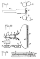
- the rendering device illustrated in FIGS. 1 to 3 essentially comprises a line-type cathode ray tube with screen on optical fibers and color mask, and a device for driving a film in front of the cathode ray tube.
- the cathode-ray tube 10 is of flat shape with a screen 20 essentially one-dimensional, for example a useful length of approximately 250 mm for a useful width of 10 mm.
- the tube 10 comprises an emitting cathode constituted by a filament 11, an electrode 12 (Wehnelt) on which an image signal is applied to modulate the electron beam emitted by the cathode, an accelerating anode 13, coils 14 for centering the beam, a dynamic focusing unit 15 making it possible to keep a focused spot on the screen along a scanning line, electromagnetic deflection coils 16 ensuring in particular horizontal scanning (line scanning), and the screen 20.
- the elements listed above are conventional component parts of a cathode ray tube. Note however that the use of electromagnetic focusing optics associated with a high resolution phosphor screen allows the formation of a spot of 30 microns in diameter, that is to say the possibility of sharing each line in about 8.OOO points.
- the deflection windings 16 further allow a vertical deflection of the beam over the useful height of the screen, which gives the possibility of scanning along several different horizontal lines. The amplitude of vertical deviation remains small enough to avoid the cushion and barrel distortions typical of conventional cathode ray tube systems.
- a fiber optic window 21 is fixed to the front face of the screen 20.
- This window 21 is made up of a large number of adjoining optical fibers substantially perpendicular to the screen 20. These fibers route to the front face of the window 21 the photons emitted in response to the impact of the electron beam on the screen 20.
- a color mask 22 is fixed in front of the window 21 of optical fibers.
- the mask 22 comprises three lines of colors R, G and B, respectively red, green and blue. Each line has a width substantially equal to the diameter of the spot on the screen 20 (for example 30 microns) and the lines are spaced from each other by a distance substantially equal to their width.
- the mask 22 is for example produced by tracing the lines R, G, B on a transparent color film (film type for slide).
- the screen 20 is chosen with a broad emission spectrum comprising the three colors R, G, B, or at least with a spectrum having emission peaks in each of these colors.
- the image support on which the image to be restored must be transferred for example, consists of a film 30 which is pressed against the mask 22 and is driven in a direction perpendicular to the horizontal scanning axis of the tube 10, in order to perform vertical scanning (raster scanning).
- the film 30 is driven by a pair of rollers 31, 32 which exert traction on the film 30 after the film has passed in front of the mask 22.
- the drive roller 31 is applied against the rear face (base) of the film 30 while the follower roller 32 which is free to rotate is applied to the other face of the film 30 (emulsion side); in this way, the tensile force is exerted on the least fragile side.
- the film 30 Before reaching the tube 10, the film 30 passes between two rollers 33, 34 on which is applied a weakly resistant torque in advance of the film in order to ensure that it is perfectly pressed against the mask 22.
- the face external of the window 21 of optical fibers, and the mask 22 have a curved profile in vertical section in order to facilitate the plating of the film.
- image supports can be used, for example film clips.
- the training for the weft scanning is for example ensured by fixing the film plane on a carriage which is moved in front of the tube 10 while pressing the film against the color mask.
- the reproduction of an image is carried out on the basis of digital information supplied to the reproduction apparatus from a host computer 17 and comprising data blocks representing the color components of the different lines of the image.
- the received data is temporarily stored in buffer registers 18 before being applied to a modulator 19 which supplies the image signal controlling the electrode 12.
- the film 30 being stationary, the red component of line 1 is printed, the green component of line 2 and blue component of line 3. Then, the film 30 is moved by a distance corresponding to the pitch between the lines of the mask 22 and a new sequence is carried out during which one over-impresses to the green component of line 2 its red component, we superimpose to the blue component of line 3 its component green and the blue component of line 4 is printed.
- the film is again moved and the same scanning sequence is repeated, which makes it possible to complete line 3 since its three blue, green and red components are then impressed.
- the information representative of a color image is available in a format using line multiplexing of the data for each color.
- successive blocks which correspond respectively to: red component of line 1, blue component of line 1, green component of line 1, red component of line 2, and so on.
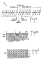
- the information which is available in the form of a line multiplexing of the data for each component must be reorganized by means of the buffer registers 18 as illustrated in FIG. 4.
- registers R4, R3, R2, V3, V2 and B2 are transferred respectively to registers R3, R2, R1, V2, V1 and B1, the data corresponding to the red, green and blue components of the row of rows n + 4 are loaded into registers R4, V3 and B2 and, the film having been moved by the distance corresponding to the pitch between lines, registers R1, V1, B1 are again read sequentially for the printing of the red components (n +1), green (n + 2) and blue (n + 3). This is done until the end of the image restitution.
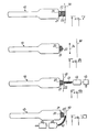
- the mask 22 being produced by printing a color film, it is possible to "peel" the film emulsion for the deposit directly on the window 21 of optical fibers.
- the extra thickness provided by the emulsion is then limited to a few microns, compared to around 200 microns for the complete film.
- the mask 22 by providing its outer face with a thin layer of protective material, for example a resin with hardener, or a semi-transparent metallic layer deposited by evaporation.
- a thin layer of protective material for example a resin with hardener, or a semi-transparent metallic layer deposited by evaporation.
- Another solution to avoid abrasion consists in not moving the film 30 while keeping it in contact with the mask 22 while avoiding the drawbacks linked to the dispersion of the light coming from the optical fibers.
- the mask 22 is constituted by a film with its base 22a bonded to the fibers of the window 21 and the emulsion 22b (not “peeled") ) located on the outside.
- the color lines are formed by a succession of elementary segments separated from each other by opaque segments, the lines themselves being separated from each other by opaque lines.
- the line segments of the mask correspond to the points of the lines of the image to be restored.
- the mask 22 thus forms, as shown in Figure 6, a checkerboard whose colored boxes are spaced from each other by black edges of substantially constant thickness.
- the film to be impressed 30 is slightly spaced from the mask 22.
- the light coming from the fibers during the scanning of a line of the screen only reaches the segments of the corresponding line of the mask.
- the photons which disperse at the outlet of the fibers are either absorbed by the black areas bordering these segments, or trapped by successive reflections within the base 22a when their angle of emergence at the outlet of the fibers is strongly inclined relative to normal to the mask.
- the black areas delimiting the segments of the mask lines allow correct separation of the light information corresponding to the different points of a line of the image even when the film 30 is slightly spaced from the mask.
- a thin mask 22 such as that used for the apparatus of FIGS. 1 and 2, can be placed between the planar faces opposite the window 21 of optical fibers and an additional block 23 of optical fibers on the face outside of which the film to be impressed is plated (figure 7).
- the external face of the optical fibers 23 is curved.
- the free space between these blocks can be filled with a liquid of suitable index (for example Baume du Canada).
- FIG. 8 illustrates yet another embodiment making it possible to avoid abrasion of the mask 22.
- the latter is produced from a transparent positive color film on which the red, green and blue lines have been impressed.
- the mask 22 is placed on the emulsion side on the window 21 of optical fibers, these having a flat outer face.
- the image of the mask is taken up by an optic 24 to be formed on the film 30 to be impressed located at a distance from the tube 10. By acting on the magnification of the pick-up optics, it is then possible to enlarge the image formed. on the film.
- Figures 9 and 10 illustrate two embodiments of a color image analysis apparatus constituting another aspect of the invention.
- FIG. 9 we find the same tube 10 as that of FIGS. 1 and 2, with a screen 20 provided with a window 21 made of optical fibers, the front face of which carries a mask 22, the screen having an emission spectrum. wide or, at least emission peaks in the colors of the mask.
- that of the tube of the analysis apparatus receives a constant video signal to constitute, with the lines R, G, B of the mask, three sources of red, green and blue light.
- the image to be analyzed is carried by a transparent film 40, which is moved while being pressed against the mask 22 to perform the weft scanning (the front face of the window 21 of optical fibers and of the mask 22 is curved to facilitate the plating of the film 40).
- the light passing through the film 40 is taken up by a sheet 41 of optical fibers to be returned to a single detector 42 constituted by an opto-electronic device, such as a photo-multiplier tube which delivers an analog electrical signal.
- a single detector 42 constituted by an opto-electronic device, such as a photo-multiplier tube which delivers an analog electrical signal.
- This signal is converted into digital form by means of an analog-digital converter 43.
- the sheet 41 of optical fibers is arranged so as to be able to collect the light produced during the scanning of each of the color lines of the mask 22 .
- Operation in analysis mode is similar to that in restitution mode.
- the film 40 being stationary, the lines R, G, B of the mask are scanned successively.
- the data blocks constituted by the digital signals obtained corresponding to the different color components are recorded in buffer registers whose organization is opposite to that illustrated in FIG. 4. After a scanning sequence of the three lines of the mask, the film 40 is moved a distance equal to the step between these lines and a new scanning sequence is performed.
- the data entered in the buffer registers are read so as to be stored, for example on magnetic tape, with the format corresponding to the multiplexing by line of the red, green and blue data.
- an operation of the analysis apparatus with continuous scrolling of the image support is possible by providing a line scan with a direction having the appropriate inclination.
- FIG. 9 illustrates an apparatus for analyzing the transmission of an image carried by a transparent support.
- FIG. 9 illustrates an apparatus for analyzing the transmission of an image carried by a transparent support.
- the apparatus of FIG. 10 differs from that of FIG. 9 in that the image support 50 carrying the image to be analyzed is kept spaced from the flat front face of the mask 22. In this way, the end of the sheet 41 of optical fibers can be brought into the gap between the mask 22 and the image support 50 in order to collect part of the light reflected by the latter during the scanning of each line of the mask.
- the operation of the apparatus of FIG. 8 is similar to that of the apparatus of FIG. 9.
- the use of the mask 22 for the color analysis makes it possible to avoid the use of three detection systems, one for each color, with appropriate color separation means, as is the case when the Color analysis is performed using a white light source.
- the use of the sheet 41 of optical fibers to collect the light having passed through the support of the image to be analyzed or being reflected by this support is preferable to a recovery optic because of its better optical efficiency.
Landscapes
- Engineering & Computer Science (AREA)
- Multimedia (AREA)
- Signal Processing (AREA)
- Facsimile Scanning Arrangements (AREA)
- Vessels, Lead-In Wires, Accessory Apparatuses For Cathode-Ray Tubes (AREA)
Claims (11)
- Vorrichtung für die Wiedergabe und/oder die Analyse von farbigen Bildern auf einem Bildträger, mit: einer Kathodenstrahlröhre (10) für einen Zeilenbildschirm (20), einer Anordnung von optischen Fasern (21), die auf der Vorderseite des Röhrenbildschirms befestigt ist, einer Farbenmaske (22), die vor der Anordnung der optischen Fasern angeordnet ist und wenigstens drei Zeilen (R, V, B) von unterschiedlichen Farben aufweist, Einrichtungen zum Abtasten des Bildschirms mittels des elektronischen Bündels der Röhre gemäß unterschiedlicher Zeilen entsprechend den Zeilen der Farbenmaske, und mit Einrichtungen (31-34) zur Relativbewegung zwischen der Röhre und einem Bildträger (30; 40; 50), der vor der Maske sitzt, derart, um jede Bildzeile auf dem Träger durch jedes Bündel zu durchlaufen, das durch die Abtastungen des Bildschirms gemäß den unterschiedlichen Zeilen der Farbenmaske erzeugt wird,
wobei die Vorrichtung dadurch gekennzeichnet ist, daß die Farbenmaske (22) durch einen Farbfilm gebildet wird, der vor der Anordnung der optischen Fasern befestigt ist, und auf dem die Zeilen (R, V, B) von unterschiedlichen Farben ausgebildet wurden. - Vorrichtung für die Wiedergabe eines Farbbildes auf einen Bildträger, mit einer Kathodenstrahlröhre (10) für einen Zeilenbildschirm (20), einer Anordnung von optischen Fasern (21), die auf der Vorderseite des Bildschirms der Röhre festgelegt ist, einer Farbenmaske (22), die vor der Anordnung der optischen Fasern angeordnet ist und wenigstens drei Zeilen (R, V, B) unterschiedlicher Farben aufweist, mit Einrichtungen zum Löschen des Bildschirms durch das elektronische Bündel der Röhre gemäß unterschiedlicher Zeilen, entsprechend den Zeilen der Farbenmaske, Modulationseinrichtungen des elektronischen Bündels der Röhre in Abhängigkeit eines Bildsignals, das dem wiederzugebenden Bild entspricht und das ausgehend von Daten erzeugt wird, die jeweils einen Farbbestandteil einer Bildzeile darstellen, und mit Einrichtungen (31-34) zum relativen Bewegen zwischen der Röhre und einem Bildträger (30), der vor der Maske derart angeordnet ist, daß er auf dem Träger jede zu wiedergebende Bildzeile mittels Überlagerung seiner Farbbildbestandteile bildet, die jeweils bei dem Vorbeigehen des Bildträgers vor der entsprechenden Farbzeile gebildet wird, die von dem elektronischen Bündel abgetastet wird,
dadurch gekennzeichnet, daß:- die Farbenmaske (22) durch einen Farbfilm gebildet wird, der vor der optischen Faseranordnung befestigt ist, und auf dem die Zeilen (R, V, B) von unterschiedlichen Farben gebildet wurden, und- Zwischenspeicher (R4, R3, R2, R1, V3, V2, V1, B2, B1) vorgesehen sind, um die Daten aufzunehmen, die die Farbbestandteile der Bildzeilen darstellen, und derart angeordnet werden, daß sie das sequentielle Lesen der genannten Daten in der Ordnung erlauben, in der die Farbbestandteile der Bildzeilen auf dem Bildträger gebildet werden. - Vorrichtung nach Anspruch 2,
dadurch gekennzeichnet, daß der Bildträger (30) und die Farbenmaske (22) in Bezug zueinander Schritt für Schritt bewegt werden in eine Richtung, senkrecht zu jener der Maskenzeilen. - Vorrichtung nach Anspruch 2,
dadurch gekennzeichnet, daß der Bildträger (30) und die Farbenmaske (22) bezüglich zueinander auf kontinuierliche Weise bewegt werden, und die Farbzeilen der Maske bezüglich der Senkrechten zur Richtung der relativen Bewegung zwischen der Maske und dem Bildträger geneigt sind. - Vorrichtung zum Lesen eines Farbbildes, getragen von einem Bildträger, mit einer Kathodenstrahlröhre (10) für einen Zeilenbildschirm (20), einer Anordnung von optischen Fasern (21), die auf der Vorderseite der Röhre befestigt sind, Einrichtungen zum Abtasten des Bildschirms durch ein elektronisches Bündel der Röhre gemäß unterschiedlicher Farbzeilen, und mit Einrichtungen zum relativen Bewegen zwischen der Röhre und dem Bildträger (40; 50), der vor der Röhre derart angeordnet ist, daß jede Bildzeile, die von dem Bildträger getragen wird nacheinander durch ein jedes der Bündel abgetastet wird, die durch die Abtastungen des Bildschirms gemäß den unterschiedlichen Farbzeilen erzeugt werden,
dadurch gekennzeichnet, daß:- eine Farbenmaske (22) in Form eines Films vor der Anordnung von optischen Fasern (21) befestigt ist und wenigstens drei Zeilen unterschiedlicher Farben (R, V, B) trägt,- Abtasteinrichtungen des Bildschirms angeordnet werden, um eine Abtastung gemäß unterschiedlicher Zeilen zu erzeugen, entsprechend den Zeilen der Farbenmaske (22),- Einrichtungen (41) der Lichtübertragung mit optischen Fasern angeordnet sind, mit einem ersten Ende, das in der Nähe des Bildträgers (30; 40) angeordnet ist, um die Lichtsignale aufzunehmen, die den Farbbestandteilen der unterschiedlichen Bildzeilen entsprechen, und- Abtasteinrichtungen (42) in der Nähe eines anderen Endes der Übertragungseinrichtungen von Licht angeordnet sind, um die genannten Lichtsignale in numerische Daten umzuwandeln. - Vorrichtung nach Anspruch 5,
dadurch gekennzeichnet, daß der Bildträger (40) durchsichtig ist, und zwischen der Farbenmaske (22) und den Einrichtungen (41) der Übertragung von Licht angeordnet ist, die das Licht sammeln, das den Bildträger durchquert hat. - Vorrichtung nach Anspruch 5,
dadurch gekennzeichnet, daß der Lichtträger (50) opak ist, und die Einrichtungen (41) zum Übertragen von Licht ihr erstes Ende in einem Intervall angeordnet haben zwischen der Farbenmaske (22) und dem Bildträger (50), um das von dem Bildträger zurückgeworfene Licht aufzunehmen. - Vorrichtung nach einem der Ansprüche 1 bis 7,
dadurch gekennzeichnet, daß die Farbenmaske (22) mit einem durchsichtigen Schutzüberzug an ihrer Außenseite versehen ist, gegen die der Bildträger bezüglich der Maske bewegt wird. - Vorrichtung nach einem der Ansprüche 1 bis 8,
dadurch gekennzeichnet, daß eine zweite optische Faseranordnung (23) vor der Farbenmaske (22) festgelegt ist, wobei der Bildträger bezüglich der Maske vor der zweiten Anordnung von optischen Fasern bewegt wird. - Vorrichtung nach einem der Ansprüche 1 bis 9,
dadurch gekennzeichnet, daß ein optisches System (24) zwischen der Farbenmaske (22) und dem Bildträger angeordnet ist. - Vorrichtung nach einem der Ansprüche 1 bis 10,
dadurch gekennzeichnet, daß jede Zeile (R, V, B) der Farbenmaske (22) aus Elementarsegmenten gebildet ist, die voneinander durch opake oder lichtundurchlässige Segmente getrennt sind, und von der oder jeder benachbarten Zeile durch eine lichtundurchlässige Zeile getrennt ist.
Applications Claiming Priority (2)
| Application Number | Priority Date | Filing Date | Title |
|---|---|---|---|
| FR8511258A FR2585527B1 (fr) | 1985-07-23 | 1985-07-23 | Dispositif pour la restitution et/ou l'analyse d'images en couleurs utilisant un tube cathodique ligne a ecran sur fibres optiques |
| FR8511258 | 1985-07-23 |
Publications (2)
| Publication Number | Publication Date |
|---|---|
| EP0213017A1 EP0213017A1 (de) | 1987-03-04 |
| EP0213017B1 true EP0213017B1 (de) | 1991-07-10 |
Family
ID=9321555
Family Applications (1)
| Application Number | Title | Priority Date | Filing Date |
|---|---|---|---|
| EP86401625A Expired - Lifetime EP0213017B1 (de) | 1985-07-23 | 1986-07-21 | Gerät zur farbigen Wiedergabe und/oder Lesen von Bildern mittels einer Linienkathodenstrahlröhre mit einem mit optischen Fasern überzogen Schirm |
Country Status (5)
| Country | Link |
|---|---|
| US (1) | US4694221A (de) |
| EP (1) | EP0213017B1 (de) |
| JP (1) | JPS6271374A (de) |
| DE (1) | DE3680165D1 (de) |
| FR (1) | FR2585527B1 (de) |
Families Citing this family (9)
| Publication number | Priority date | Publication date | Assignee | Title |
|---|---|---|---|---|
| JPH0792723B2 (ja) * | 1986-07-21 | 1995-10-09 | 株式会社日立製作所 | 座標入力装置 |
| DE3916790A1 (de) * | 1988-07-15 | 1990-01-18 | Pioneer Electronic Corp | Anzeigegeraet |
| JPH0316466A (ja) * | 1989-06-14 | 1991-01-24 | Sharp Corp | 密着型イメージセンサ |
| US5426453A (en) * | 1992-08-18 | 1995-06-20 | Alliant Techsystems, Inc. | Media spacing system for fiber optic cathode ray tube printer |
| KR19980057663A (ko) * | 1996-12-30 | 1998-09-25 | 손욱 | 음극선관의 대전 형성방법 및 이대전 방지막을 갖는 음극선관 |
| JPH11231439A (ja) | 1998-02-17 | 1999-08-27 | Noritsu Koki Co Ltd | 印画紙露光方法とその方法を用いた光デジタルプリンター |
| JP2003045359A (ja) * | 2001-07-30 | 2003-02-14 | Hitachi Ltd | 陰極線管 |
| JP2004060520A (ja) | 2002-07-29 | 2004-02-26 | Denso Corp | スタータ |
| JP4165362B2 (ja) | 2003-10-08 | 2008-10-15 | 株式会社デンソー | スタータ |
Family Cites Families (12)
| Publication number | Priority date | Publication date | Assignee | Title |
|---|---|---|---|---|
| NL284863A (de) * | 1962-02-28 | |||
| US3299434A (en) * | 1964-07-30 | 1967-01-17 | Joseph T Mcnaney | System for transferring data from a storage medium to a record medium |
| US3209191A (en) * | 1964-08-11 | 1965-09-28 | Douglas Aircraft Co Inc | Cathode ray tube screen and ambient light filter |
| US3735032A (en) * | 1969-04-09 | 1973-05-22 | Westinghouse Electric Corp | Television pick-up tube device |
| US3609233A (en) * | 1969-09-29 | 1971-09-28 | American Optical Corp | Electron tube facsimile apparatus |
| US3818131A (en) * | 1970-02-02 | 1974-06-18 | Ampex | Fiber optic cathode ray tube with anti-static discharge means |
| US4309720A (en) * | 1976-06-03 | 1982-01-05 | Tektronix, Inc. | Apparatus and method for producing an image on a sensitized surface |
| GB1552560A (en) * | 1976-06-03 | 1979-09-12 | Tektronix Inc | Apparatus and method for copying images onto sensitized surfaces |
| JPS5757454A (en) * | 1980-09-22 | 1982-04-06 | Yokogawa Hokushin Electric Corp | Cathode ray display tube for color print |
| JPS57154970A (en) * | 1981-03-19 | 1982-09-24 | Yokogawa Hokushin Electric Corp | Optical information reader |
| JPS586663A (ja) * | 1981-07-06 | 1983-01-14 | Nippon Telegr & Teleph Corp <Ntt> | 密着形イメ−ジセンサ |
| US4499501A (en) * | 1982-09-01 | 1985-02-12 | Tektronix, Inc. | Image transfer method and apparatus |
-
1985
- 1985-07-23 FR FR8511258A patent/FR2585527B1/fr not_active Expired
-
1986
- 1986-07-17 US US06/886,385 patent/US4694221A/en not_active Expired - Fee Related
- 1986-07-21 DE DE8686401625T patent/DE3680165D1/de not_active Expired - Fee Related
- 1986-07-21 EP EP86401625A patent/EP0213017B1/de not_active Expired - Lifetime
- 1986-07-22 JP JP61170963A patent/JPS6271374A/ja active Pending
Also Published As
| Publication number | Publication date |
|---|---|
| US4694221A (en) | 1987-09-15 |
| JPS6271374A (ja) | 1987-04-02 |
| DE3680165D1 (de) | 1991-08-14 |
| FR2585527B1 (fr) | 1989-07-07 |
| FR2585527A1 (fr) | 1987-01-30 |
| EP0213017A1 (de) | 1987-03-04 |
Similar Documents
| Publication | Publication Date | Title |
|---|---|---|
| EP0135413B1 (de) | Abbildungsanordnung für ein Grossdimensionsfernsehbild | |
| FR2595833A1 (fr) | Table tracante photographique utilisant un modulateur de lumiere et procede pour reproduire des graphiques par exposition | |
| EP0213017B1 (de) | Gerät zur farbigen Wiedergabe und/oder Lesen von Bildern mittels einer Linienkathodenstrahlröhre mit einem mit optischen Fasern überzogen Schirm | |
| FR2696843A1 (fr) | Appareil de prise de vues à distance, à haute résolution, pour porteur aérien. | |
| EP0305274A1 (de) | Verfahren und Vorrichtung zur Erzeugung von stereoskopischen Bildern | |
| FR2569481A1 (fr) | Systeme d'enregistrement de teintes continues | |
| FR2510853A1 (fr) | Systeme de television et moyen transducteur d'image, moyen de visualisation, dispositif pour former un signal video composite et dispositif pour decoder ce signal a y utiliser | |
| FR2787591A1 (fr) | Appareil de projection a laser donnant une image de grandes dimensions | |
| FR2509556A1 (fr) | Dispositif de balayage et d'enregistrement d'image | |
| FR2509939A1 (fr) | Dispositif d'enregistrement d'image | |
| FR2463433A1 (fr) | Dispositif de reproduction d'une image a densite variable de teinte | |
| FR2601146A1 (fr) | Dispositif d'adressage optique et son utilisation dans des dispositifs imageurs electrooptiques | |
| FR2509877A1 (fr) | Repartiteur de faisceau lumineux | |
| FR2541783A1 (fr) | Systeme d'analyse optique a miroirs situes dans un plan d'un disque rotatif | |
| FR2577371A1 (fr) | Dispositif de projection d'image de television sur grand ecran | |
| FR2688059A1 (fr) | Procede optique de determination de positions relatives de deux pieces et dispositif pour sa mise en óoeuvre. | |
| EP0829870A1 (de) | Magnetooptischer Wiedergabekopf und Wiedergabegerät für die Wiedergabe von magnetischen Daten auf mehreren Spuren | |
| CA1223351A (fr) | Appareil de numerisation d'image par analyse au moyen d'un faisceau lumineux | |
| FR2589300A1 (fr) | Dispositif permettant de transformer une representation d'une image en couleur en un signal electrique, et inversement | |
| EP0611454A1 (de) | Vorrichtung für Mikroabtastung und Infrarotkamera ausgestattet mit einer solchen Vorrichtung | |
| JPS63168618A (ja) | 撮像装置 | |
| EP3983837B1 (de) | Optische matrixarraykomponente zum fokussieren eines einfallenden lichtstrahls auf eine reihe von punkten | |
| FR2571195A1 (fr) | Procede et dispositif de restitution d'images par balayage suivant des lignes successives d'un support photosensible a l'aide d'un faisceau lumineux module | |
| CH622363A5 (en) | Method for producing images by the use of electrostatic techniques, and apparatus for implementing this method | |
| EP0511899A1 (de) | Vorrichtung für Mikroabtastung, Infrarotkamera ausgestattet mit einer solchen Vorrichtung und Verfahren zur Herstellung dieser Vorrichtung |
Legal Events
| Date | Code | Title | Description |
|---|---|---|---|
| PUAI | Public reference made under article 153(3) epc to a published international application that has entered the european phase |
Free format text: ORIGINAL CODE: 0009012 |
|
| AK | Designated contracting states |
Kind code of ref document: A1 Designated state(s): DE FR GB IT SE |
|
| 17P | Request for examination filed |
Effective date: 19870805 |
|
| RAP1 | Party data changed (applicant data changed or rights of an application transferred) |
Owner name: SOCIETE EUROPEENNE DE PROPULSION (S.E.P.) SOCIETE |
|
| 17Q | First examination report despatched |
Effective date: 19890814 |
|
| GRAA | (expected) grant |
Free format text: ORIGINAL CODE: 0009210 |
|
| AK | Designated contracting states |
Kind code of ref document: B1 Designated state(s): DE FR GB IT SE |
|
| REF | Corresponds to: |
Ref document number: 3680165 Country of ref document: DE Date of ref document: 19910814 |
|
| RAP2 | Party data changed (patent owner data changed or rights of a patent transferred) |
Owner name: MATRA SEP IMAGERIE ET INFORMATIQUE, SOCIETE ANONYM |
|
| ITF | It: translation for a ep patent filed | ||
| GBT | Gb: translation of ep patent filed (gb section 77(6)(a)/1977) | ||
| PLBE | No opposition filed within time limit |
Free format text: ORIGINAL CODE: 0009261 |
|
| STAA | Information on the status of an ep patent application or granted ep patent |
Free format text: STATUS: NO OPPOSITION FILED WITHIN TIME LIMIT |
|
| 26N | No opposition filed | ||
| PGFP | Annual fee paid to national office [announced via postgrant information from national office to epo] |
Ref country code: GB Payment date: 19940719 Year of fee payment: 9 |
|
| PGFP | Annual fee paid to national office [announced via postgrant information from national office to epo] |
Ref country code: DE Payment date: 19940721 Year of fee payment: 9 |
|
| PGFP | Annual fee paid to national office [announced via postgrant information from national office to epo] |
Ref country code: SE Payment date: 19940731 Year of fee payment: 9 |
|
| EAL | Se: european patent in force in sweden |
Ref document number: 86401625.8 |
|
| PG25 | Lapsed in a contracting state [announced via postgrant information from national office to epo] |
Ref country code: GB Effective date: 19950721 |
|
| PG25 | Lapsed in a contracting state [announced via postgrant information from national office to epo] |
Ref country code: SE Effective date: 19950722 |
|
| GBPC | Gb: european patent ceased through non-payment of renewal fee |
Effective date: 19950721 |
|
| PG25 | Lapsed in a contracting state [announced via postgrant information from national office to epo] |
Ref country code: DE Effective date: 19960402 |
|
| EUG | Se: european patent has lapsed |
Ref document number: 86401625.8 |
|
| PGFP | Annual fee paid to national office [announced via postgrant information from national office to epo] |
Ref country code: FR Payment date: 19970731 Year of fee payment: 12 |
|
| PG25 | Lapsed in a contracting state [announced via postgrant information from national office to epo] |
Ref country code: FR Free format text: LAPSE BECAUSE OF NON-PAYMENT OF DUE FEES Effective date: 19990331 |
|
| REG | Reference to a national code |
Ref country code: FR Ref legal event code: ST |
|
| PG25 | Lapsed in a contracting state [announced via postgrant information from national office to epo] |
Ref country code: IT Free format text: LAPSE BECAUSE OF NON-PAYMENT OF DUE FEES;WARNING: LAPSES OF ITALIAN PATENTS WITH EFFECTIVE DATE BEFORE 2007 MAY HAVE OCCURRED AT ANY TIME BEFORE 2007. THE CORRECT EFFECTIVE DATE MAY BE DIFFERENT FROM THE ONE RECORDED. Effective date: 20050721 |