EP0213017B1 - Device for reproducing and/or reading images in colour using a linear cathode ray tube with a screen clad with optical fibres - Google Patents
Device for reproducing and/or reading images in colour using a linear cathode ray tube with a screen clad with optical fibres Download PDFInfo
- Publication number
- EP0213017B1 EP0213017B1 EP86401625A EP86401625A EP0213017B1 EP 0213017 B1 EP0213017 B1 EP 0213017B1 EP 86401625 A EP86401625 A EP 86401625A EP 86401625 A EP86401625 A EP 86401625A EP 0213017 B1 EP0213017 B1 EP 0213017B1
- Authority
- EP
- European Patent Office
- Prior art keywords
- mask
- color
- lines
- image
- image carrier
- Prior art date
- Legal status (The legal status is an assumption and is not a legal conclusion. Google has not performed a legal analysis and makes no representation as to the accuracy of the status listed.)
- Expired - Lifetime
Links
Images
Classifications
-
- H—ELECTRICITY
- H04—ELECTRIC COMMUNICATION TECHNIQUE
- H04N—PICTORIAL COMMUNICATION, e.g. TELEVISION
- H04N1/00—Scanning, transmission or reproduction of documents or the like, e.g. facsimile transmission; Details thereof
- H04N1/46—Colour picture communication systems
- H04N1/48—Picture signal generators
- H04N1/482—Picture signal generators using the same detector device sequentially for different colour components
- H04N1/484—Picture signal generators using the same detector device sequentially for different colour components with sequential colour illumination of the original
-
- H—ELECTRICITY
- H04—ELECTRIC COMMUNICATION TECHNIQUE
- H04N—PICTORIAL COMMUNICATION, e.g. TELEVISION
- H04N1/00—Scanning, transmission or reproduction of documents or the like, e.g. facsimile transmission; Details thereof
- H04N1/46—Colour picture communication systems
- H04N1/50—Picture reproducers
- H04N1/504—Reproducing the colour component signals line-sequentially
Definitions
- the present invention relates to a device for the reproduction and / or analysis of color images.
- a particular, but not exclusive, field of application of the invention is that of the reproduction or analysis of very high resolution images, such as those received from observation satellites.
- a line cathode-ray tube with screen on optical fibers presents, compared to the conventional cathode-ray tubes two essential characteristics: the scanning is carried out exclusively or mainly in only one direction, and the screen of the tube is provided externally with a set of joined optical fibers which transport the photons produced by the electron beam at a certain distance from the screen.
- US-A-4,309,720 relates to a color image reproducing device using a tube cathodic line with screen on optical fibers, the screen being provided with phosphorescent bands providing different colors.
- a line of the image to be reproduced is formed by superimposing its color components, each color component being produced by scanning the corresponding phosphorescent band by means of the electron beam of the tube.
- document EP-A-0 198 794 shows a device for reproducing images on an image medium, device of the type comprising: a cathode ray tube with line screen, a set of optical fibers fixed on the front face of the screen of the tube, a color mask located in front of the set of optical fibers and comprising at least three lines of different colors, means for scanning the screen by the electron beam along different lines corresponding to the lines of the color mask and means for relative displacement between the tube and an image support located at the front of the mask, so as to traverse each line of the image on the support by each of the beams produced by the scans of the screen along the different lines of the color mask.
- the object of the present invention is to provide a device making it possible to carry out, relatively inexpensively, the reproduction and / or analysis of color images with a high resolution.
- the color mask consists of a film color fixed in front of the set of optical fibers and on which the lines of different colors were formed.
- the color lines produced on the mask can be very narrow without this resulting in a high production cost. It is for example possible to form lines a few tens of microns wide on a color photographic film.
- the electron beam of the tube is modulated as a function of an image signal which corresponds to the image to be rendered and which is in the form of data each representing a color component of an image line.
- the image support is moved relative to the mask so as to form on this support each line of the image to be restored by superposition of its color components each formed during the passage of the image support in front of the corresponding line of the mask. colors scanned by the electron beam.
- Buffer registers receive said data representing the color components image lines and are arranged so as to allow the sequential reading of said data in the order in which the color components of the image lines are formed on the image support.
- the image to be analyzed is scanned line by line in each of the colors and the quantity of light having passed through the image support (analysis in transmission of an image on a transparent support) or reflected by the support of image (analysis in reflection of an image on an opaque support) is sent to a single detector by means of recovery optics or optical fibers, to be measured and digitized.
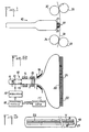
- the rendering device illustrated in FIGS. 1 to 3 essentially comprises a line-type cathode ray tube with screen on optical fibers and color mask, and a device for driving a film in front of the cathode ray tube.
- the cathode-ray tube 10 is of flat shape with a screen 20 essentially one-dimensional, for example a useful length of approximately 250 mm for a useful width of 10 mm.
- the tube 10 comprises an emitting cathode constituted by a filament 11, an electrode 12 (Wehnelt) on which an image signal is applied to modulate the electron beam emitted by the cathode, an accelerating anode 13, coils 14 for centering the beam, a dynamic focusing unit 15 making it possible to keep a focused spot on the screen along a scanning line, electromagnetic deflection coils 16 ensuring in particular horizontal scanning (line scanning), and the screen 20.
- the elements listed above are conventional component parts of a cathode ray tube. Note however that the use of electromagnetic focusing optics associated with a high resolution phosphor screen allows the formation of a spot of 30 microns in diameter, that is to say the possibility of sharing each line in about 8.OOO points.
- the deflection windings 16 further allow a vertical deflection of the beam over the useful height of the screen, which gives the possibility of scanning along several different horizontal lines. The amplitude of vertical deviation remains small enough to avoid the cushion and barrel distortions typical of conventional cathode ray tube systems.
- a fiber optic window 21 is fixed to the front face of the screen 20.
- This window 21 is made up of a large number of adjoining optical fibers substantially perpendicular to the screen 20. These fibers route to the front face of the window 21 the photons emitted in response to the impact of the electron beam on the screen 20.
- a color mask 22 is fixed in front of the window 21 of optical fibers.
- the mask 22 comprises three lines of colors R, G and B, respectively red, green and blue. Each line has a width substantially equal to the diameter of the spot on the screen 20 (for example 30 microns) and the lines are spaced from each other by a distance substantially equal to their width.
- the mask 22 is for example produced by tracing the lines R, G, B on a transparent color film (film type for slide).
- the screen 20 is chosen with a broad emission spectrum comprising the three colors R, G, B, or at least with a spectrum having emission peaks in each of these colors.
- the image support on which the image to be restored must be transferred for example, consists of a film 30 which is pressed against the mask 22 and is driven in a direction perpendicular to the horizontal scanning axis of the tube 10, in order to perform vertical scanning (raster scanning).
- the film 30 is driven by a pair of rollers 31, 32 which exert traction on the film 30 after the film has passed in front of the mask 22.
- the drive roller 31 is applied against the rear face (base) of the film 30 while the follower roller 32 which is free to rotate is applied to the other face of the film 30 (emulsion side); in this way, the tensile force is exerted on the least fragile side.
- the film 30 Before reaching the tube 10, the film 30 passes between two rollers 33, 34 on which is applied a weakly resistant torque in advance of the film in order to ensure that it is perfectly pressed against the mask 22.
- the face external of the window 21 of optical fibers, and the mask 22 have a curved profile in vertical section in order to facilitate the plating of the film.
- image supports can be used, for example film clips.
- the training for the weft scanning is for example ensured by fixing the film plane on a carriage which is moved in front of the tube 10 while pressing the film against the color mask.
- the reproduction of an image is carried out on the basis of digital information supplied to the reproduction apparatus from a host computer 17 and comprising data blocks representing the color components of the different lines of the image.
- the received data is temporarily stored in buffer registers 18 before being applied to a modulator 19 which supplies the image signal controlling the electrode 12.
- the film 30 being stationary, the red component of line 1 is printed, the green component of line 2 and blue component of line 3. Then, the film 30 is moved by a distance corresponding to the pitch between the lines of the mask 22 and a new sequence is carried out during which one over-impresses to the green component of line 2 its red component, we superimpose to the blue component of line 3 its component green and the blue component of line 4 is printed.
- the film is again moved and the same scanning sequence is repeated, which makes it possible to complete line 3 since its three blue, green and red components are then impressed.
- the information representative of a color image is available in a format using line multiplexing of the data for each color.
- successive blocks which correspond respectively to: red component of line 1, blue component of line 1, green component of line 1, red component of line 2, and so on.
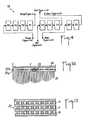
- the information which is available in the form of a line multiplexing of the data for each component must be reorganized by means of the buffer registers 18 as illustrated in FIG. 4.
- registers R4, R3, R2, V3, V2 and B2 are transferred respectively to registers R3, R2, R1, V2, V1 and B1, the data corresponding to the red, green and blue components of the row of rows n + 4 are loaded into registers R4, V3 and B2 and, the film having been moved by the distance corresponding to the pitch between lines, registers R1, V1, B1 are again read sequentially for the printing of the red components (n +1), green (n + 2) and blue (n + 3). This is done until the end of the image restitution.
- the mask 22 being produced by printing a color film, it is possible to "peel" the film emulsion for the deposit directly on the window 21 of optical fibers.
- the extra thickness provided by the emulsion is then limited to a few microns, compared to around 200 microns for the complete film.
- the mask 22 by providing its outer face with a thin layer of protective material, for example a resin with hardener, or a semi-transparent metallic layer deposited by evaporation.
- a thin layer of protective material for example a resin with hardener, or a semi-transparent metallic layer deposited by evaporation.
- Another solution to avoid abrasion consists in not moving the film 30 while keeping it in contact with the mask 22 while avoiding the drawbacks linked to the dispersion of the light coming from the optical fibers.
- the mask 22 is constituted by a film with its base 22a bonded to the fibers of the window 21 and the emulsion 22b (not “peeled") ) located on the outside.
- the color lines are formed by a succession of elementary segments separated from each other by opaque segments, the lines themselves being separated from each other by opaque lines.
- the line segments of the mask correspond to the points of the lines of the image to be restored.
- the mask 22 thus forms, as shown in Figure 6, a checkerboard whose colored boxes are spaced from each other by black edges of substantially constant thickness.
- the film to be impressed 30 is slightly spaced from the mask 22.
- the light coming from the fibers during the scanning of a line of the screen only reaches the segments of the corresponding line of the mask.
- the photons which disperse at the outlet of the fibers are either absorbed by the black areas bordering these segments, or trapped by successive reflections within the base 22a when their angle of emergence at the outlet of the fibers is strongly inclined relative to normal to the mask.
- the black areas delimiting the segments of the mask lines allow correct separation of the light information corresponding to the different points of a line of the image even when the film 30 is slightly spaced from the mask.
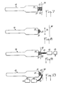
- a thin mask 22 such as that used for the apparatus of FIGS. 1 and 2, can be placed between the planar faces opposite the window 21 of optical fibers and an additional block 23 of optical fibers on the face outside of which the film to be impressed is plated (figure 7).
- the external face of the optical fibers 23 is curved.
- the free space between these blocks can be filled with a liquid of suitable index (for example Baume du Canada).
- FIG. 8 illustrates yet another embodiment making it possible to avoid abrasion of the mask 22.
- the latter is produced from a transparent positive color film on which the red, green and blue lines have been impressed.
- the mask 22 is placed on the emulsion side on the window 21 of optical fibers, these having a flat outer face.
- the image of the mask is taken up by an optic 24 to be formed on the film 30 to be impressed located at a distance from the tube 10. By acting on the magnification of the pick-up optics, it is then possible to enlarge the image formed. on the film.
- Figures 9 and 10 illustrate two embodiments of a color image analysis apparatus constituting another aspect of the invention.
- FIG. 9 we find the same tube 10 as that of FIGS. 1 and 2, with a screen 20 provided with a window 21 made of optical fibers, the front face of which carries a mask 22, the screen having an emission spectrum. wide or, at least emission peaks in the colors of the mask.
- that of the tube of the analysis apparatus receives a constant video signal to constitute, with the lines R, G, B of the mask, three sources of red, green and blue light.
- the image to be analyzed is carried by a transparent film 40, which is moved while being pressed against the mask 22 to perform the weft scanning (the front face of the window 21 of optical fibers and of the mask 22 is curved to facilitate the plating of the film 40).
- the light passing through the film 40 is taken up by a sheet 41 of optical fibers to be returned to a single detector 42 constituted by an opto-electronic device, such as a photo-multiplier tube which delivers an analog electrical signal.
- a single detector 42 constituted by an opto-electronic device, such as a photo-multiplier tube which delivers an analog electrical signal.
- This signal is converted into digital form by means of an analog-digital converter 43.
- the sheet 41 of optical fibers is arranged so as to be able to collect the light produced during the scanning of each of the color lines of the mask 22 .
- Operation in analysis mode is similar to that in restitution mode.
- the film 40 being stationary, the lines R, G, B of the mask are scanned successively.
- the data blocks constituted by the digital signals obtained corresponding to the different color components are recorded in buffer registers whose organization is opposite to that illustrated in FIG. 4. After a scanning sequence of the three lines of the mask, the film 40 is moved a distance equal to the step between these lines and a new scanning sequence is performed.
- the data entered in the buffer registers are read so as to be stored, for example on magnetic tape, with the format corresponding to the multiplexing by line of the red, green and blue data.
- an operation of the analysis apparatus with continuous scrolling of the image support is possible by providing a line scan with a direction having the appropriate inclination.
- FIG. 9 illustrates an apparatus for analyzing the transmission of an image carried by a transparent support.
- FIG. 9 illustrates an apparatus for analyzing the transmission of an image carried by a transparent support.
- the apparatus of FIG. 10 differs from that of FIG. 9 in that the image support 50 carrying the image to be analyzed is kept spaced from the flat front face of the mask 22. In this way, the end of the sheet 41 of optical fibers can be brought into the gap between the mask 22 and the image support 50 in order to collect part of the light reflected by the latter during the scanning of each line of the mask.
- the operation of the apparatus of FIG. 8 is similar to that of the apparatus of FIG. 9.
- the use of the mask 22 for the color analysis makes it possible to avoid the use of three detection systems, one for each color, with appropriate color separation means, as is the case when the Color analysis is performed using a white light source.
- the use of the sheet 41 of optical fibers to collect the light having passed through the support of the image to be analyzed or being reflected by this support is preferable to a recovery optic because of its better optical efficiency.
Description
La présente invention est relative à un dispositif pour la restitution et/ou l'analyse d'images en couleurs.The present invention relates to a device for the reproduction and / or analysis of color images.
Un domaine particulier, mais non exclusif d'application de l'invention est celui de la restitution ou de l'analyse d'images à très haute résolution, telles que celles reçues de satellites d'observation.A particular, but not exclusive, field of application of the invention is that of the reproduction or analysis of very high resolution images, such as those received from observation satellites.
Dans ce domaine particulier, on connaît déjà des appareils utilisant soit un tambour tournant sur lequel un film est impressionné ligne par ligne au moyen d'une source de lumière modulée déplacée pas à pas le long du tambour, soit un berceau sur lequel un film est plaqué et est impressionné ou analysé au moyen d'une source de lumière éclairant un miroir tournant avec un balayage ligne par ligne par déplacement relatif entre le berceau et le miroir. On pourra se référer en particulier aux brevets français FR-A-2 293 841 et FR-A-2 571 198 déposés par la demanderesse.In this particular field, devices are already known using either a rotating drum on which a film is impressed line by line by means of a modulated light source moved step by step along the drum, or a cradle on which a film is plated and is impressed or analyzed by means of a light source illuminating a rotating mirror with a scanning line by line by relative displacement between the cradle and the mirror. Reference may be made in particular to French patents FR-A-2 293 841 and FR-A-2 571 198 filed by the applicant.
Ces appareils connus donnent toute satisfaction sur le plan de la qualité des résultats obtenus, mais sont relativement onéreux en raison notamment des exigences que doivent satisfaire les moyens mécaniques utilisés pour le balayage ligne afin d'obtenir la précision voulue.These known devices give full satisfaction in terms of the quality of the results obtained, but are relatively expensive, in particular because of the requirements that must be met by the mechanical means used for line scanning in order to obtain the desired precision.
Il est donc souhaitable de pouvoir disposer de moyens de balayage qui, tout en permettant toujours une haute résolution, soient d'un coût moins élevé.It is therefore desirable to be able to have scanning means which, while still allowing high resolution, are of lower cost.
Pour la reproduction d'images en couleurs sur un support photosensible, il a déjà été proposé d'utiliser un tube cathodique ligne à écran sur fibres optiques pour effectuer le balayage ligne du support photosensible. Un tube cathodique ligne à écran sur fibres optiques présente, par rapport aux tubes cathodiques classiques deux particularités essentielles : le balayage est effectué exclusivement ou principalement dans une seule direction, et l'écran du tube est muni extérieurement d'un ensemble de fibres optiques accolées qui acheminent à une certaine distance de l'écran les photons produits par le faisceau électronique.For the reproduction of color images on a photosensitive support, it has already been proposed to use a line cathode-ray tube with screen on optical fibers to carry out the line scanning of the photosensitive support. A line cathode-ray tube with screen on optical fibers presents, compared to the conventional cathode-ray tubes two essential characteristics: the scanning is carried out exclusively or mainly in only one direction, and the screen of the tube is provided externally with a set of joined optical fibers which transport the photons produced by the electron beam at a certain distance from the screen.
Le brevet des US-A- 4 309 720 a pour objet un dispositif de reproduction d'images en couleurs utilisant un tube cathodique ligne à écran sur fibres optiques, l'écran étant muni de bandes phosphorescentes fournissant des couleurs différentes. Une ligne de l'image à reproduire est formée en superposant ses composantes de couleur, chaque composante de couleur étant produite par balayage de la bande phosphorescente correspondante au moyen du faisceau électronique du tube.US-A-4,309,720 relates to a color image reproducing device using a tube cathodic line with screen on optical fibers, the screen being provided with phosphorescent bands providing different colors. A line of the image to be reproduced is formed by superimposing its color components, each color component being produced by scanning the corresponding phosphorescent band by means of the electron beam of the tube.
L'utilisation de bandes phosphorescentes soulève toutefois plusieurs difficultés.The use of phosphorescent strips, however, raises several difficulties.
D'abord, pour équilibrer les différentes couleurs, il est nécessaire de disposer de phosphores qui produisent de mêmes intensités lumineuses en réponse à une même excitation, ou, si les phosphores ont des rendements quantiques différents, de moduler l'intensité du faisceau électronique en fonction de la couleur.First, to balance the different colors, it is necessary to have phosphors which produce the same light intensities in response to the same excitation, or, if the phosphors have different quantum yields, to modulate the intensity of the electron beam by color function.
Ensuite, le dépôt de bandes de phosphore est d'un coût relativement élevé, d'autant plus si l'on cherche à réaliser des bandes très étroites.Then, the deposition of phosphorus bands is relatively high cost, all the more if one seeks to produce very narrow bands.
Mais même avec des techniques très élaborées, il est en pratique très difficile de réaliser de façon satisfaisante des bandes de largeur inférieure à 200 microns.But even with very sophisticated techniques, it is very difficult in practice to produce strips of width less than 200 microns satisfactorily.
Si l'on recherche une résolution inférieure par exemple d'environ 30 microns (dimension du spot), il est alors nécessaire de stocker un assez grand nombre de données représentant les composantes de couleurs de lignes successives pour pouvoir restituer ces données dans l'ordre qui convient afin de produire les composantes de couleur des lignes d'image successives sur le support d'image qui défile devant l'écran.If a lower resolution is sought, for example around 30 microns (spot size), it is then necessary to store a large number of data representing the color components of successive lines in order to be able to restore these data in order which is suitable for producing the color components of successive image lines on the image medium which scrolls past the screen.
Il a par ailleurs été proposé, dans le document DE-A-2 016 303, de réaliser un tube de prise de vue pour caméra de télévision muni, sur sa face frontale, d'un filtre formé de bandes de couleurs, alternativement rouge, bleue et verte. L'image à analyser est focalisée, à travers le filtre et un ensemble de fibres optiques, sur une photocathode située du côté intérieur de la face frontale du tube. L'image électronique produite par la photocathode est à son tour focalisée sur une cible balayée par un faisceau électronique. Le filtre en bandes peut être produit par exposition photographique d'un film couleur en présence d'un modèle à bandes.It has also been proposed, in document DE-A-2 016 303, to produce a shooting tube for television camera provided, on its front face, with a filter formed by bands of colors, alternately red, blue and green. The image to be analyzed is focused, through the filter and a set of optical fibers, onto a photocathode located on the inside of the front face of the tube. The electronic image produced by the photocathode is in turn focused on a target scanned by a electron beam. The band filter can be produced by photographic exposure of a color film in the presence of a band model.
En outre, le document EP-A-0 198 794, publié après la date de priorité du présent brevet, mais bénéficiant d'une date de priorité antérieure, montre un dispositif de reproduction d'images sur un support d'image, dispositif du type comprenant : un tube cathodique à écran ligne, un ensemble de fibres optiques fixé sur la face avant de l'écran du tube, un masque de couleur situé devant l'ensemble de fibres optiques et comportant au moins trois lignes de couleurs différentes, des moyens de balayage de l'écran par le faisceau électronique suivant différentes lignes correspondant aux lignes du masque de couleurs et des moyens de déplacement relatif entre le tube et un support d'image situé à l'avant du masque, de manière à parcourir chaque ligne de l'image sur le support par chacun des faisceaux produits par les balayages de l'écran suivant les différentes lignes du masque de couleurs.In addition, document EP-A-0 198 794, published after the priority date of this patent, but benefiting from an earlier priority date, shows a device for reproducing images on an image medium, device of the type comprising: a cathode ray tube with line screen, a set of optical fibers fixed on the front face of the screen of the tube, a color mask located in front of the set of optical fibers and comprising at least three lines of different colors, means for scanning the screen by the electron beam along different lines corresponding to the lines of the color mask and means for relative displacement between the tube and an image support located at the front of the mask, so as to traverse each line of the image on the support by each of the beams produced by the scans of the screen along the different lines of the color mask.
La présente invention a pour but de fournir un dispositif permettant de réaliser de façon relativement peu coûteuse la restitution et/ou l'analyse d'images en couleurs avec une résolution élevée.The object of the present invention is to provide a device making it possible to carry out, relatively inexpensively, the reproduction and / or analysis of color images with a high resolution.
Ce but est atteint au moyen d'un dispositif du type de celui du document EP-A-0 198 174, tel que défini ci-dessus, et dans lequel, conformément à l'invention, le masque de couleurs est constitué par un film couleur fixé devant l'ensemble de fibres optiques et sur lequel ont été formées les lignes de couleurs différentes.This object is achieved by means of a device of the type of that of document EP-A-0 198 174, as defined above, and in which, in accordance with the invention, the color mask consists of a film color fixed in front of the set of optical fibers and on which the lines of different colors were formed.
L'utilisation d'un masque de couleurs en forme de film placé devant l'écran à fibres optiques présente d'incontestables avantages par rapport aux bandes de matériaux phosphorescents.The use of a film-like color mask placed in front of the fiber optic screen has indisputable advantages over strips of phosphorescent materials.
D'abord, au lieu de nécessiter des phosphores ayant des pics d'émission relativement étroits, on peut utiliser un écran à spectre large.First, instead of requiring phosphors having relatively narrow emission peaks, a broad spectrum screen can be used.
Ensuite, les lignes de couleurs réalisées sur le masque peuvent être très étroites sans que cela entraîne un coût de production élevé. Il est par exemple possible de former des lignes de quelques dizaines de microns de largeur sur un film photographique couleur.Then, the color lines produced on the mask can be very narrow without this resulting in a high production cost. It is for example possible to form lines a few tens of microns wide on a color photographic film.
On notera encore que le choix des couleurs est pratiquement illimité et que le réglage de l'intensité du faisceau lumineux dans chaque couleur peut être réalisé facilement au moment de la fabrication du masque.It will also be noted that the choice of colors is practically unlimited and that the adjustment of the intensity of the light beam in each color can be carried out easily at the time of manufacture of the mask.
En mode restitution, le faisceau électronique du tube est modulé en fonction d'un signal d'image qui correspond à l'image à restituer et qui est sous forme de données représentant chacune une composante de couleur d'une ligne d'image. Le support d'image est déplacé par rapport au masque de manière à former sur ce support chaque ligne de l'image à restituer par superposition de ses composantes de couleurs formées chacune lors du passage du support d'image devant la ligne correspondante du masque de couleurs balayée par le faisceau électronique. Des registres tampons reçoivent lesdites données représentant les composantes de couleurs des lignes d'image et sont agencés de manière à permettre la lecture séquentielle desdites données dans l'ordre dans lequel les composantes de couleurs des lignes de l'image sont formées sur le support d'image.In restitution mode, the electron beam of the tube is modulated as a function of an image signal which corresponds to the image to be rendered and which is in the form of data each representing a color component of an image line. The image support is moved relative to the mask so as to form on this support each line of the image to be restored by superposition of its color components each formed during the passage of the image support in front of the corresponding line of the mask. colors scanned by the electron beam. Buffer registers receive said data representing the color components image lines and are arranged so as to allow the sequential reading of said data in the order in which the color components of the image lines are formed on the image support.
En mode analyse, l'image à analyser est balayée ligne par ligne dans chacune des couleurs et la quantité de lumière ayant traversé le support d'image (analyse en transmission d'une image sur un support transparent) ou réfléchie par le support d'image ( analyse en réflexion d'une image sur un support opaque) est envoyée sur un détecteur unique au moyen d'une optique de reprise ou de fibres optiques, pour être mesurée et numérisée.In analysis mode, the image to be analyzed is scanned line by line in each of the colors and the quantity of light having passed through the image support (analysis in transmission of an image on a transparent support) or reflected by the support of image (analysis in reflection of an image on an opaque support) is sent to a single detector by means of recovery optics or optical fibers, to be measured and digitized.
L'invention sera mieux comprise à la lecture de la description faite, ci-après, à titre indicatif mais non limitatif, en référence aux dessins sur lesquels :
- la figure 1 est une vue schématique en élévation latérale d'un dispositif de restitution conforme à l'invention,
- la figure 2 est une vue de dessus illustrant de façon plus détaillée le tube cathodique du dispositif de la figure 1,
- la figure 3 est une vue en bout du tube cathodique de la figure 2, montrant le masque de couleurs,
- la figure 4 illustre de façon très schématique l'organisation de registres tampons d'où sont successivement extraites les données représentant les composantes de couleurs des lignes d'une image à restituer,
- la figure 5 est une vue partielle en coupe illustrant une première variante de réalisation du masque de couleurs dans un dispositif tel que celui de la figure 1,
- la figure 6 est une vue partielle en plan du masque selon la variante de réalisation illustrée par la figure 5,
- la figure 7 est une vue en coupe illustrant une autre variante de réalisation de la partie avant du tube cathodique dans un dispositif tel que celui de la figure 1,
- la figure 8 illustre encore une autre variante de réalisation évitant un contact direct entre le masque de couleurs et le support photosensible sur lequel est formée l'image à restituer,
- la figure 9 est une vue schématique en élévation latérale d'un dispositif d'analyse en transmission conforme à l'invention, et
- la figure 10 est une vue schématique en élévation latérale d'un mode de réalisation d'un dispositif d'analyse en réflexion conforme à l'invention.
- FIG. 1 is a schematic side elevation view of a rendering device according to the invention,
- FIG. 2 is a top view illustrating in more detail the cathode ray tube of the device of FIG. 1,
- FIG. 3 is an end view of the cathode ray tube of FIG. 2, showing the mask of colors,
- FIG. 4 very schematically illustrates the organization of buffer registers from which are successively extracted the data representing the color components of the lines of an image to be restored,
- FIG. 5 is a partial sectional view illustrating a first alternative embodiment of the color mask in a device such as that of FIG. 1,
- FIG. 6 is a partial plan view of the mask according to the variant embodiment illustrated in FIG. 5,
- FIG. 7 is a sectional view illustrating another alternative embodiment of the front part of the cathode ray tube in a device such as that of FIG. 1,
- FIG. 8 illustrates yet another alternative embodiment avoiding direct contact between the color mask and the photosensitive support on which the image is formed. restore,
- FIG. 9 is a schematic side elevation view of a transmission analysis device according to the invention, and
- Figure 10 is a schematic side elevational view of an embodiment of a reflection analysis device according to the invention.
Sur tous les dessins, les mêmes références sont utilisées pour désigner des parties identiques ou similaires.In all the drawings, the same references are used to designate identical or similar parts.
L'appareil de restitution illustré par les figures 1 à 3 comprend essentielement un tube cathodique de type ligne avec écran sur fibres optiques et masque de couleurs, et un dispositif d'entraînement d'un film devant le tube cathodique.The rendering device illustrated in FIGS. 1 to 3 essentially comprises a line-type cathode ray tube with screen on optical fibers and color mask, and a device for driving a film in front of the cathode ray tube.
Comme on peut le voir plus particulièrement sur les figures 1 et 2, le tube cathodique 10 est de forme aplatie avec un écran 20 essentiellement unidimensionnel, par exemple une longueur utile d'environ 250 mm pour une largeur utile de 10 mm. A partir de son extrémité arrière, le tube 10 comporte une cathode émettrice constituée par un filament 11, une électrode 12 (Wehnelt) sur laquelle est appliqué un signal d'image pour moduler le faisceau électronique émis par la cathode, une anode accélératrice 13, des bobines 14 de centrage du faisceau, une unité 15 de focalisation dynamique permettant de conserver sur l'écran un spot focalisé tout le long d'une ligne de balayage, des bobinages 16 de déflexion électromagnétique assurant notamment le balayage horizontal (balayage ligne), et l'écran 20. Les éléments énumérés ci-avant sont des parties constitutives classiques d'un tube cathodique. On notera toutefois que l'utilisation d'une optique à focalisation électromagnétique associée à un écran au phosphore à haute résolution permet la formation d'un spot de 30 microns de diamètre, c'est-à-dire la possibilité de partager chaque ligne en environ 8.OOO points. Les bobinages de déflexion 16 permettent en outre une déviation verticale du faisceau sur la hauteur utile de l'écran, ce qui donne la possibilité d'effectuer un balayage suivant plusieurs lignes horizontales différentes. L'amplitude de déviation verticale reste toutefois suffisamment petite pour éviter les distorsions en coussinnet et en tonneau propres aux systèmes classiques à tubes cathodiques.As can be seen more particularly in FIGS. 1 and 2, the cathode-
Une fenêtre en fibres optiques 21 est fixée sur la face avant de l'écran 20. Cette fenêtre 21 est constituée par un grand nombre de fibres optiques accolées sensiblement perpendiculaires à l'écran 20. Ces fibres acheminent jusqu' à la face avant de la fenêtre 21 les photons émis en réponse à l'impact du faisceau électronique sur l'écran 20. Selon une caractéristique de l'invention, un masque de couleurs 22 est fixé devant la fenêtre 21 de fibres optiques. Comme on peut le voir sur la figure 3, le masque 22 comprend trois lignes de couleurs R, V et B, respectivement rouge, verte et bleue. Chaque ligne a une largeur sensiblement égale au diamètre du spot sur l'écran 20 (par exemple 30 microns) et les lignes sont espacées l'une de l'autre d'une distance sensiblement égale à leur largeur. Le masque 22 est par exemple réalisé en traçant les lignes R, V, B sur un film couleur transparent (type film pour diapositive). Pour obtenir des lignes rigoureusement droites et parallèles entre elles avec la largeur voulue, on utilise avantageusement un appareil de restitution couleur à haute résolution de l'art antérieur du type de ceux décrits dans les brevets français précités No FR-A-2 293 841 et FR-A-2571 198 ou de ceux produits par la demanderesse sous la dénomination "Vizircolor". L'écran 20 est choisi avec un spectre d'émission large comprenant les trois couleurs R, V, B, ou au moins avec un spectre présentant des pics d'émission dans chacune de ces couleurs.A fiber
Le support d'image sur lequel doit être reportée l'image à restituer est par exemple constitué par un film 30 qui est plaqué sur le masque 22 et est entraîné dans une direction perpendiculaire à l'axe de balayage horizontal du tube 10, afin de réaliser le balayage vertical (balayage trame). L'entraînement du film 30 est assuré au moyen d'une paire de rouleaux 31, 32 qui exercent une traction sur le film 30 après le passage de celui-ci devant le masque 22. Le rouleau moteur 31 est appliqué contre la face arrière (base) du film 30 tandis que le rouleau suiveur 32 qui est libre en rotation est appliqué sur l'autre face du film 30 (côté émulsion) ; de la sorte, l'effort de traction est exercé sur le côté le moins fragile. Avant de parvenir devant le tube 10, le film 30 passe entre deux rouleaux 33, 34 sur lesquels est appliqué un couple faiblement résistant à l'avance du film afin d'assurer le parfait plaquage de celui-ci contre le masque 22. La face externe de la fenêtre 21 de fibres optiques, et le masque 22 ont un profil courbé en section verticale afin de faciliter le plaquage du film.The image support on which the image to be restored must be transferred, for example, consists of a
D'autres supports d'image peuvent être utilisés, par exemple des plans films. L'entraînement pour le balayage trame est par exemple assuré en fixant le plan film sur un chariot qui est déplacé devant le tube 10 tout en plaquant le film contre le masque de couleurs.Other image supports can be used, for example film clips. The training for the weft scanning is for example ensured by fixing the film plane on a carriage which is moved in front of the
En balayant l'écran du tube suivant des lignes correspondant aux trois lignes de couleurs du masque 22 (le passage d'une ligne à l'autre étant réalisé par action sur les moyens de déflexion verticale), on obtient trois sources de lumière rouge, verte, bleue.By scanning the screen of the tube along lines corresponding to the three color lines of the mask 22 (the passage from one line to the other being carried out by action on the vertical deflection means), three sources of red light are obtained, green, blue.
La restitution d'une image est effectuée à partir d'informations numériques fournies à l'appareil de restitution à partir d'un calculateur hôte 17 et comprenant des blocs de données représentant les composantes de couleur des différentes lignes de l'image. Les données reçues sont stockées temporairement dans des registres tampons 18 avant d'être appliquées à un modulateur 19 qui fournit le signal d'image commandant l'électrode 12. Le film 30 étant immobile, on impressionne la composante rouge de la ligne 1, la composante verte de la ligne 2 et la composante bleue de la ligne 3. Ensuite, le film 30 est déplacé d'une distance correspondant au pas entre les lignes du masque 22 et on procède à une nouvelle séquence au cours de laquelle on sur-impressionne à la composante verte de la ligne 2 sa composante rouge, on surimpressionne à la composante bleue de la ligne 3 sa composante verte et on impressionne la composante bleue de la ligne 4. Le film est à nouveau déplacé et la même séquence de balayage est répétée, ce qui permet de compléter la ligne 3 puisque ses trois composantes bleue, verte et rouge sont alors impressionnées.The reproduction of an image is carried out on the basis of digital information supplied to the reproduction apparatus from a
Généralement, l'information représentative d'une image en couleurs est disponible suivant un format utilisant un multiplexage par ligne des données pour chaque couleur. Ainsi, on trouve par exemple des blocs successifs qui correspondent respectivement à : composante rouge de la ligne 1, composante bleue de la ligne 1, composante verte de la ligne 1, composante rouge de la ligne 2, et ainsi de suite. Aussi, avant d'être appliquées à l'appareil de restitution, les informations qui sont disponibles sous forme d'un multiplexage par lignes des données pour chaque composante doivent être réorganisées au moyen des registres tampons 18 comme illustré par la figure 4. Les données correspondant aux composantes rouges de quatre lignes successives de rangs n+3, n+2, n+1, n sont enregistrées dans des registres R4, R3, R2 et R1, les données correspondant aux composantes vertes des lignes de rangs n+3, n+2 et n+1 sont enregistrées dans des registres V3, V2 et V1 et les données correspondant aux composantes bleues des lignes de rangs n+3 et n+2 sont enregistrées dans des registres B2 et B1. La lecture séquentielle des registres R1, V1, B1 permet l'impression des composantes rouge n, verte (n+1) et bleue (n+2), le film 30 étant à l'arrêt. Ensuite, les contenus des registres R4, R3, R2, V3, V2 et B2 sont transférés respectivement dans les registres R3, R2, R1, V2, V1 et B1, les données correspondant aux composantes rouge, verte et bleue de la ligne de rang n+4 sont chargées dans les registres R4, V3 et B2 et, le film ayant été déplacé de la distance correspondnt au pas entre lignes, les registres R1, V1, B1 sont à nouveau lus séquentiellement pour l'impression des composantes rouge (n+1), verte (n+2) et bleue (n+3). On procède ainsi jusqu' à la fin de la restitution de l'image.Generally, the information representative of a color image is available in a format using line multiplexing of the data for each color. Thus, there are for example successive blocks which correspond respectively to: red component of
Le balayage ligne étant rigoureusement perpendiculaire à la direction du balayage trame, il est nécessaire de maintenir le film 30 immobile au cours de l'impression de chaque ligne. En effet, sinon, l'avance continue du film provoquerait une inclinaison systématique des lignes impressionnées.Since the line scan is strictly perpendicular to the direction of the frame scan, it is necessary to maintain the
Mais le balayage bidirectionnel du tube 10 autorise un certain nombre de corrections géométriques en temps réel au cours de la restitution de l'image.But the bidirectional scanning of the
Ainsi, il est possible d'incliner les lignes de balayage sur l'écran en agissant sur les moyens de déflexion, ce qui permet, en appliquant une tension en forme de rampe sur l'amplificateur de déflexion verticale de compenser l'inclinaison provoquée par un balayage trame réalisé de façon continue. De la sorte, le film 30 peut être entraîné en continu. Il est alors bien entendu nécessaire d'orienter les lignes du masque de couleurs parallèlement aux lignes de balayage inclinées sur l'écran 20.Thus, it is possible to tilt the scanning lines on the screen by acting on the deflection means, which makes it possible, by applying a ramp-shaped voltage on the vertical deflection amplifier, to compensate for the inclination caused by a frame scan carried out continuously. In this way, the
La possibilité d'inclinaison de la direction de balayage ligne permet par ailleurs, le cas échéant, de parfaire l'alignement du masque avec cette direction de balayage.The possibility of tilting the line scanning direction also makes it possible, if necessary, to perfect the alignment of the mask with this scanning direction.
Il est encore possible, au cours du balayage ligne, de modifier la vitesse du faisceau électronique en agissant sur les moyens de déflexion horizontale. L'accélération ou la décélération du faisceau en toute portion de ligne permet l'interpolation de points, c'est-à-dire une variation le long de la ligne du pas des points de l'image restituée par rapport aux points de l'image enregistrée. La possibilité de corrections géométriques sur l'image en temps réel et en cours de restitution constitue un avantage par rapport aux appareils de restitution à balayage essentiellement mécaniques lesquels, de par leur inertie, sont astreints à effectuer des balayages à vitesse constante.It is also possible, during line scanning, to modify the speed of the electron beam by acting on the horizontal deflection means. The acceleration or deceleration of the beam in any portion of the line allows the interpolation of points, that is to say a variation along the line of the pitch of the points of the restored image with respect to the points of the saved image. The possibility of geometric corrections on the image in real time and during restitution constitutes an advantage compared with essentially mechanical scanning restitution devices which, due to their inertia, are required to perform sweeps at constant speed.
Avec le dispositif des figures 1 et 2, il est nécessaire d'utiliser un masque 22 aussi mince que possible afin de limiter la largeur de l'intervalle entre la fenêtre de fibres optiques 21 et le film 30, ceci pour éviter une dispersion de la lumière issue des fibres optiques.With the device in FIGS. 1 and 2, it is necessary to use a
Le masque 22 étant réalisé par impression d'un film couleur, il est possible de "peler" l'émulsion du film pour la déposer directement sur la fenêtre 21 de fibres optiques. La surépaisseur apportée par l'émulsion est alors limitée à quelques microns, contre environ 200 microns pour le film complet.The
Toutefois, le défilement du film à impressionner en contact avec le masque risque d'entraîner à plus ou moins brève échéance une abrasion puis un arrachement du masque.However, the running of the film to be impressed in contact with the mask risks leading to more or less short-term abrasion and then tearing of the mask.
Il est alors possible de protéger le masque 22 en munissant sa face extérieure d'une couche mince de matériau protecteur, par exemple une résine avec durcisseur, ou une couche métallique semi-transparente déposée par évaporation.It is then possible to protect the
Une autre solution pour éviter l'abrasion consiste à ne pas déplacer le film 30 en le maintenant au contact du masque 22 tout en évitant les inconvénients liés à la dispersion de la lumière issue des fibres optiques.Another solution to avoid abrasion consists in not moving the
Ainsi, dans la variante de réalisation illustrée (à échelle agrandie) sur les figures 5 et 6 , le masque 22 est constitué par un film avec sa base 22a collée sur les fibres de la fenêtre 21 et l'émulsion 22b (non "pelée") située du côté extérieur. Les lignes de couleurs sont constituées par une succession de segments élémentaires séparés les uns des autres par des segments opaques, les lignes étant elles-mêmes séparées les unes des autres par des lignes opaques. Les segments des lignes du masque correspondent aux points des lignes de l'image à restituer. Le masque 22 forme ainsi, comme le montre la figure 6, un damier dont les cases colorées sont espacées les unes des autres par des bords noirs d'épaisseur sensiblement constante.Thus, in the variant embodiment illustrated (on an enlarged scale) in FIGS. 5 and 6, the
Le film à impressionner 30 est légèrement espacé du masque 22. Comme le montre la figure 5, la lumière issue des fibres au cours du balayage d'une ligne de l'écran n'attteint que les segments de la ligne correspondante du masque. En effet, les photons qui se dispersent en sortie des fibres sont soit absorbés par les zones noires bordant ces segments, soit piégés par réflexions successives au sein de la base 22a lorsque leur angle d'émergence en sortie des fibres est fortement incliné par rapport à la normale au masque. De plus, les zones noires délimitant les segments des lignes du masque permettent une séparation correcte des informations lumineuses correspondant aux différents points d'une ligne de l'image même lorsque le film 30 est légèrement espacé du masque.The film to be impressed 30 is slightly spaced from the
D'autres solutions sont possibles pour éviter une abrasion du masque.Other solutions are possible to avoid abrasion of the mask.
Ainsi, un masque mince 22, tel que celui utilisé pour l'appareil des figures 1 et 2, peut être placé entre les faces planes en regard de la fenêtre 21 de fibres optiques et d'un bloc supplémentaire 23 de fibres optiques sur la face externe duquel le film à impressionner est plaqué (figure 7). Pour faciliter le plaquage du film, la face externe des fibres optiques 23 est bombée. Afin de parfaire le couplage optique entre les blocs de fibres 21 et 23, l'espace libre entre ces blocs peut être rempli d'un liquide d'indice adapté (par exemple Baume du Canada).Thus, a
La figure 8 illustre encore un autre mode de réalisation permettant d'éviter une abrasion du masque 22. Ce dernier est réalisé à partir d'un film couleur positif transparent sur lequel ont été impressionnées les lignes rouge, verte et bleue. Le masque 22 est placé côté émulsion sur la fenêtre 21 de fibres optiques, celles-ci ayant une face extérieure plane. L' image du masque est reprise par une optique 24 pour être formée sur le film 30 à impressionner situé à distance du tube 10. En agissant sur le grandissement de l'optique de reprise, il est alors possible d'agrandir l'image formée sur le film.FIG. 8 illustrates yet another embodiment making it possible to avoid abrasion of the
Les figures 9 et 10 illustrent deux modes de réalisation d'un appareil d'analyse d'image en couleurs constituant un autre aspect de l'invention.Figures 9 and 10 illustrate two embodiments of a color image analysis apparatus constituting another aspect of the invention.
Sur la figure 9, on retrouve le même tube 10 que celui des figures 1 et 2, avec un écran 20 muni d'une fenêtre 21 en fibres optiques dont la face avant porte un masque 22, l'écran ayant un spectre d'émission large ou, au moins des pics d'émission dans les couleurs du masque. Toutefois, à la différence du tube de l'appareil de restitution, celui du tube de l'appareil d'analyse reçoit un signal vidéo constant pour constituer, avec les lignes R, V, B du masque, trois sources de lumière rouge, verte et bleue. L'image à analyser est portée par un film transparent 40, qui est déplacé en étant plaqué contre le masque 22 pour effectuer le balayage trame (la face avant de la fenêtre 21 de fibres optiques et du masque 22 est bombée pour faciliter le plaquage du film 40). La lumière traversant le film 40 est reprise par une nappe 41 de fibres optiques pour être renvoyée sur un détecteur unique 42 constitué par un dispositif opto-électronique, tel qu'un tube photo-multiplicateur qui délivre un signal électrique analogique. Ce signal est converti sous forme numérique au moyen d'un convertisseur analogique-numérique 43. On notera que la nappe 41 de fibres optiques est disposée de manière à pouvoir recueillir la lumière produite au cours du balayage de chacune des lignes de couleurs du masque 22.In FIG. 9, we find the
Le fonctionnement en mode analyse est analogue à celui en mode restitution.Operation in analysis mode is similar to that in restitution mode.
Le film 40 étant immobile, les lignes R, V, B du masque sont balayées successivement. Les blocs de données constitués par les signaux numériques obtenus correspondant aux différentes composantes de couleurs sont enregistrés dans des registres tampons dont l'organisation est inverse de celle illustrée par la figure 4. Après une séquence de balayage des trois lignes du masque, le film 40 est déplacé sur une distance égale au pas entre ces lignes et une nouvelle séquence de balayage est réalisée. Les données introduites dans les registres tampons sont lues de manière à être stockées, par exemple sur bande magnétique, avec le format corespondant au multiplexage par ligne des données rouge, verte et bleue.The
Comme cela a été indiqué pour l'appareil de restitution, un fonctionnement de l'appareil d'analyse avec défilement continu du support d' image est possible en prévoyant un balayage ligne avec une direction présentant l'inclinaison appropriée.As indicated for the rendering apparatus, an operation of the analysis apparatus with continuous scrolling of the image support is possible by providing a line scan with a direction having the appropriate inclination.
La figure 9 illustre un appareil d'analyse en transmission d'une image portée par un support transparent. Dans le cas d'une image portée par un support opaque, on pourra utiliser l'appareil d'analyse en réflexion illustré par la figure 10.FIG. 9 illustrates an apparatus for analyzing the transmission of an image carried by a transparent support. In the case of an image carried by an opaque support, we can use the device of analysis in reflection illustrated by figure 10.
L'appareil de la figure 10 se distingue de celui de la figure 9 en ce que le support d'image 50 portant l'image à analyser est maintenu espacé de la face avant plane du masque 22. De la sorte, l'extrémité de la nappe 41 de fibres optiques peut être amenée dans l'intervalle entre le masque 22 et le support d'image 50 afin de recueillir une partie de la lumière réfléchie par celui-ci au cours du balayage de chaque ligne du masque. Pour le reste, le fonctionnement de l'appareil de la figure 8 est analogue à celui de l'appareil de la figure 9.The apparatus of FIG. 10 differs from that of FIG. 9 in that the
On notera que l'utilisation du masque 22 pour l'analyse en couleurs permet d'éviter le recours à trois systèmes de détection, un pour chaque couleur, avec des moyens de séparation de couleurs appropriés, comme c'est le cas lorsque l'analyse en couleurs est effectuée en utilisant une source de lumière blanche.It will be noted that the use of the
En outre, l'utilisation de la nappe 41 de fibres optiques pour recueillir la lumière ayant traversé le support de l'image à analyser ou étant réfléchie par ce support est préférable à une optique de reprise en raison de son meilleur rendement optique.In addition, the use of the
Dans-ce qui précède, on a envisagé l'utilisation d'un masque formé sur un film positif couleurs avec des lignes rouge, verte et bleue. Bien entendu, il est possible de réaliser le masque sur un film négatif couleur avec des lignes ayant comme couleurs le jaune, le magenta et le cyan.In the foregoing, we have considered the use of a mask formed on a positive color film with red, green and blue lines. Of course, it is possible to make the mask on a negative color film with lines having colors like yellow, magenta and cyan.
Claims (11)
- Device for the restitution and/or analysis of color images on an image carrier, comprising: a cathode ray tube (10) with a line screen (20), an assembly of optical fibers (21) fixed on the front face of the tube screen, a color mask (22) situated in front of the optical fiber assembly and comprising at least three lines (R,V,B) of different colors, means of scanning the screen by the electron beam of the tube along different lines corresponding to the lines of the color mask; and means (31-34) of relative displacement between the tube and an image carrier (30;40;50) situated in front of the mask, so that each line of the image on the carrier is scanned by each of the beams produced by the scannings of the screen along the different lines of the color mask, device characterized in that the color mask (22) is constituted by a color film fixed in front of the optical fiber assembly and on which the lines (R,V,B) of different colors have been formed.
- Device for the restitution of a color image on an image carrier, comprising a cathode ray tube (10) with a line screen (20), an assembly of optical fibers (21) fixed on the front face of the tube screen, a color mask (22) in film form, fixed in front of the optical fiber assembly and comprising at least three lines (R,V,B) of different colors, means of scanning the screen by the electron beam of the tube along different lines corresponding to the lines of the color mask; means of modulating the electron beam of the tube as a function of an image signal which corresponds to the image to be restituted and is worked out from data representing each one a color component of the color of a line of image, and means (31-34) of relative displacement between the tube and an image carrier (30) situated in front of the mask so as to form on said carrier each line of the image to be restituted by superimposition of its color components each one being formed when the image carrier passes in front of the corresponding line of color scanned by the electron beam, device characterized in that:- the color mask (22) is constituted by a color film fixed in front of the optical fiber assembly and on which the lines (R,V,B) of different colors, are formed, and- buffer registers (R4, R3, R2, R1, V3, V2, V1) are provided for receiving said data representing the color components of the lines of image and are so arranged as to enable sequential reading of the data in the order in which the color components of the lines of the image are formed on the image carrier.
- Device according to claim 2, characterized in that the image carrier (30) and the color mask (22) are moved one with respect to the other stepwise, in a direction perpendicular to the direction of the lines of the mask.
- Device according to claim 2, characterized in that the image carrier (30) and the color mask (22) are moved one with respect to the other in continuous manner, and the lines of colors of the mask are inclined with respect to the perpendicular to the direction of relative displacement between the mask and the image carrier.
- Device for analyzing a color image carried by an image carrier, comprising a cathode ray tube (10) with a line screen (20), an assembly of optical fibers (21) fixed on the front face of the tube screen, means of scanning the screen by the electron beam of the tube along different lines of colors, and means of relative displacement between the tube and the image carrier (40;50) situated in front of the tube, so that each line of the image carried by the image carrier is scanned successively by each of the beams produced by the scannings of the screen along the different lines of colors, characterized in that:- a color mask (22) in film form is fixed in front of the optical fiber assembly (21) and carries at least three lines of different colors (R,V,B),- screen scanning means are arranged for scanning along different lines corresponding to the lines of the color mask (22),- optical fiber means (41) for transmitting light, are disposed with a first end situated close to the image carrier (30;40) to pick up the light signals representing color components of the different lines Of the image and- detection means (42) are situated close to another end of said light transmission means for converting said light signals to digital data.
- Device according to claim 5, characterized in that the image carrier (40) is transparent and is situated between the color mask (22) and said light transmission means (41) picking up the light which has gone through the image carrier.
- Device according to claim 5, characterized in that the image carrier (50) is opaque and said light transmission means (41) have their first end situated in an interval provided between the color mask (22) and the image carrier (50) to pick up the light reflected by the image carrier.
- Device according to any one of claims 1 to 7, characterized in that the mask of colors (22) is provided with a transparent protective coating on its external face against which the image carrier is moved relatively to the mask.
- Device according to any one of claims 1 to 8, characterized in that a second assembly of optical fibers (23) is fixed before the color mask (22), the image carrier being moved with respect to the mask in front of the second assembly of optical fibers.
- Device according to any one of claims 1 to 9, characterized in that an optical system (24) is provided between the color mask (22) and the image carrier.
- Device according to any one of claims 1 to 20, characterized in that each line (R,V,B) of the color mask (22) is formed of elementary segments separated one from the other by opaque segments, and is separated from the or each adjacent lines by an opaque line.
Applications Claiming Priority (2)
| Application Number | Priority Date | Filing Date | Title |
|---|---|---|---|
| FR8511258 | 1985-07-23 | ||
| FR8511258A FR2585527B1 (en) | 1985-07-23 | 1985-07-23 | DEVICE FOR THE RESTORATION AND / OR ANALYSIS OF COLOR IMAGES USING A CATHODE RAY TUBE WITH SCREEN ON OPTICAL FIBERS |
Publications (2)
| Publication Number | Publication Date |
|---|---|
| EP0213017A1 EP0213017A1 (en) | 1987-03-04 |
| EP0213017B1 true EP0213017B1 (en) | 1991-07-10 |
Family
ID=9321555
Family Applications (1)
| Application Number | Title | Priority Date | Filing Date |
|---|---|---|---|
| EP86401625A Expired - Lifetime EP0213017B1 (en) | 1985-07-23 | 1986-07-21 | Device for reproducing and/or reading images in colour using a linear cathode ray tube with a screen clad with optical fibres |
Country Status (5)
| Country | Link |
|---|---|
| US (1) | US4694221A (en) |
| EP (1) | EP0213017B1 (en) |
| JP (1) | JPS6271374A (en) |
| DE (1) | DE3680165D1 (en) |
| FR (1) | FR2585527B1 (en) |
Families Citing this family (9)
| Publication number | Priority date | Publication date | Assignee | Title |
|---|---|---|---|---|
| JPH0792723B2 (en) * | 1986-07-21 | 1995-10-09 | 株式会社日立製作所 | Coordinate input device |
| DE3916790A1 (en) * | 1988-07-15 | 1990-01-18 | Pioneer Electronic Corp | Display device |
| JPH0316466A (en) * | 1989-06-14 | 1991-01-24 | Sharp Corp | Contact type image sensor |
| US5426453A (en) * | 1992-08-18 | 1995-06-20 | Alliant Techsystems, Inc. | Media spacing system for fiber optic cathode ray tube printer |
| KR19980057663A (en) * | 1996-12-30 | 1998-09-25 | 손욱 | Method for forming charge of cathode ray tube and cathode ray tube having antistatic film |
| JPH11231439A (en) | 1998-02-17 | 1999-08-27 | Noritsu Koki Co Ltd | Photographic paper exposing method and optical digital printer using the same |
| JP2003045359A (en) * | 2001-07-30 | 2003-02-14 | Hitachi Ltd | Cathode ray tube |
| JP2004060520A (en) | 2002-07-29 | 2004-02-26 | Denso Corp | Starter |
| JP4165362B2 (en) | 2003-10-08 | 2008-10-15 | 株式会社デンソー | Starter |
Family Cites Families (12)
| Publication number | Priority date | Publication date | Assignee | Title |
|---|---|---|---|---|
| NL284863A (en) * | 1962-02-28 | |||
| US3299434A (en) * | 1964-07-30 | 1967-01-17 | Joseph T Mcnaney | System for transferring data from a storage medium to a record medium |
| US3209191A (en) * | 1964-08-11 | 1965-09-28 | Douglas Aircraft Co Inc | Cathode ray tube screen and ambient light filter |
| US3735032A (en) * | 1969-04-09 | 1973-05-22 | Westinghouse Electric Corp | Television pick-up tube device |
| US3609233A (en) * | 1969-09-29 | 1971-09-28 | American Optical Corp | Electron tube facsimile apparatus |
| US3818131A (en) * | 1970-02-02 | 1974-06-18 | Ampex | Fiber optic cathode ray tube with anti-static discharge means |
| US4309720A (en) * | 1976-06-03 | 1982-01-05 | Tektronix, Inc. | Apparatus and method for producing an image on a sensitized surface |
| GB1552560A (en) * | 1976-06-03 | 1979-09-12 | Tektronix Inc | Apparatus and method for copying images onto sensitized surfaces |
| JPS5757454A (en) * | 1980-09-22 | 1982-04-06 | Yokogawa Hokushin Electric Corp | Cathode ray display tube for color print |
| JPS57154970A (en) * | 1981-03-19 | 1982-09-24 | Yokogawa Hokushin Electric Corp | Optical information reader |
| JPS586663A (en) * | 1981-07-06 | 1983-01-14 | Nippon Telegr & Teleph Corp <Ntt> | Appressed type image sensor |
| US4499501A (en) * | 1982-09-01 | 1985-02-12 | Tektronix, Inc. | Image transfer method and apparatus |
-
1985
- 1985-07-23 FR FR8511258A patent/FR2585527B1/en not_active Expired
-
1986
- 1986-07-17 US US06/886,385 patent/US4694221A/en not_active Expired - Fee Related
- 1986-07-21 EP EP86401625A patent/EP0213017B1/en not_active Expired - Lifetime
- 1986-07-21 DE DE8686401625T patent/DE3680165D1/en not_active Expired - Fee Related
- 1986-07-22 JP JP61170963A patent/JPS6271374A/en active Pending
Also Published As
| Publication number | Publication date |
|---|---|
| JPS6271374A (en) | 1987-04-02 |
| EP0213017A1 (en) | 1987-03-04 |
| US4694221A (en) | 1987-09-15 |
| FR2585527A1 (en) | 1987-01-30 |
| DE3680165D1 (en) | 1991-08-14 |
| FR2585527B1 (en) | 1989-07-07 |
Similar Documents
| Publication | Publication Date | Title |
|---|---|---|
| EP0135413B1 (en) | Display system for a television picture of large dimensions | |
| FR2595833A1 (en) | PHOTOGRAPHIC TRACING TABLE USING A LIGHT MODULATOR AND METHOD FOR REPRODUCING GRAPHICS BY EXPOSURE | |
| EP0213017B1 (en) | Device for reproducing and/or reading images in colour using a linear cathode ray tube with a screen clad with optical fibres | |
| EP0305274B1 (en) | Method and arrangement for generating stereoscopic images | |
| FR2696843A1 (en) | High resolution remote camera for aerial carrier. | |
| EP0014609A1 (en) | Large screen visualisation apparatus | |
| FR2569481A1 (en) | CONTINUOUS COLOR REGISTRATION SYSTEM | |
| FR2510853A1 (en) | TELEVISION SYSTEM AND MEDIUM IMAGE TRANSDUCER, VISUALIZATION MEANS, DEVICE FOR FORMING COMPOSITE VIDEO SIGNAL, AND DEVICE FOR DECODING THIS SIGNAL FOR USE THEREOF | |
| FR2509556A1 (en) | IMAGE SCANNING AND RECORDING DEVICE | |
| FR2787591A1 (en) | Laser image large screen image projection having light source/modulation vertical sweep mirror impinging and relay lens polygonal horizontal rotating mirror reflecting horizontal sweep. | |
| FR2509939A1 (en) | IMAGE RECORDING DEVICE | |
| FR2463433A1 (en) | DEVICE FOR REPRODUCING A VARIABLE DENSITY IMAGE OF HUE | |
| FR2509877A1 (en) | LIGHT BEAM DISTRIBUTOR | |
| FR2577371A1 (en) | Wide-screen television picture projection device | |
| FR2688059A1 (en) | OPTICAL METHOD FOR DETERMINING POSITIONS RELATING TO TWO PARTS AND DEVICE FOR ITS IMPLEMENTATION. | |
| FR2502881A1 (en) | METHOD AND INSTALLATION FOR STEREOSCOPIC REPRODUCTION OF TELEVISION SIGNALS | |
| EP0829870A1 (en) | Magnetooptical reproducing head and apparatus for reproducing magnetically recorded data from multiple tracks | |
| CA1223351A (en) | Image digitizing apparatus using light beam scanning | |
| FR2589300A1 (en) | DEVICE FOR TRANSFORMING A REPRESENTATION OF A COLOR IMAGE INTO AN ELECTRICAL SIGNAL, AND INVERSE | |
| WO1993009463A1 (en) | Device for microscanning and infrared camera provided with such device | |
| JPS63168618A (en) | Image pickup device | |
| FR2571195A1 (en) | Method and device for restoring images by scanning along successive lines of a photosensitive medium with the aid of a modulated light beam | |
| CH622363A5 (en) | Method for producing images by the use of electrostatic techniques, and apparatus for implementing this method | |
| FR2471710A1 (en) | METHOD FOR OPTOELECTRONIC TRANSMISSION OF AN IMAGE ORIGINAL | |
| EP0511899A1 (en) | Microscanning device, infra-red camera equipped with such a device and method for manufacturing this device |
Legal Events
| Date | Code | Title | Description |
|---|---|---|---|
| PUAI | Public reference made under article 153(3) epc to a published international application that has entered the european phase |
Free format text: ORIGINAL CODE: 0009012 |
|
| AK | Designated contracting states |
Kind code of ref document: A1 Designated state(s): DE FR GB IT SE |
|
| 17P | Request for examination filed |
Effective date: 19870805 |
|
| RAP1 | Party data changed (applicant data changed or rights of an application transferred) |
Owner name: SOCIETE EUROPEENNE DE PROPULSION (S.E.P.) SOCIETE |
|
| 17Q | First examination report despatched |
Effective date: 19890814 |
|
| GRAA | (expected) grant |
Free format text: ORIGINAL CODE: 0009210 |
|
| AK | Designated contracting states |
Kind code of ref document: B1 Designated state(s): DE FR GB IT SE |
|
| REF | Corresponds to: |
Ref document number: 3680165 Country of ref document: DE Date of ref document: 19910814 |
|
| RAP2 | Party data changed (patent owner data changed or rights of a patent transferred) |
Owner name: MATRA SEP IMAGERIE ET INFORMATIQUE, SOCIETE ANONYM |
|
| ITF | It: translation for a ep patent filed |
Owner name: DR. ING. A. RACHELI & C. |
|
| GBT | Gb: translation of ep patent filed (gb section 77(6)(a)/1977) | ||
| PLBE | No opposition filed within time limit |
Free format text: ORIGINAL CODE: 0009261 |
|
| STAA | Information on the status of an ep patent application or granted ep patent |
Free format text: STATUS: NO OPPOSITION FILED WITHIN TIME LIMIT |
|
| 26N | No opposition filed | ||
| PGFP | Annual fee paid to national office [announced via postgrant information from national office to epo] |
Ref country code: GB Payment date: 19940719 Year of fee payment: 9 |
|
| PGFP | Annual fee paid to national office [announced via postgrant information from national office to epo] |
Ref country code: DE Payment date: 19940721 Year of fee payment: 9 |
|
| PGFP | Annual fee paid to national office [announced via postgrant information from national office to epo] |
Ref country code: SE Payment date: 19940731 Year of fee payment: 9 |
|
| EAL | Se: european patent in force in sweden |
Ref document number: 86401625.8 |
|
| PG25 | Lapsed in a contracting state [announced via postgrant information from national office to epo] |
Ref country code: GB Effective date: 19950721 |
|
| PG25 | Lapsed in a contracting state [announced via postgrant information from national office to epo] |
Ref country code: SE Effective date: 19950722 |
|
| GBPC | Gb: european patent ceased through non-payment of renewal fee |
Effective date: 19950721 |
|
| PG25 | Lapsed in a contracting state [announced via postgrant information from national office to epo] |
Ref country code: DE Effective date: 19960402 |
|
| EUG | Se: european patent has lapsed |
Ref document number: 86401625.8 |
|
| PGFP | Annual fee paid to national office [announced via postgrant information from national office to epo] |
Ref country code: FR Payment date: 19970731 Year of fee payment: 12 |
|
| PG25 | Lapsed in a contracting state [announced via postgrant information from national office to epo] |
Ref country code: FR Free format text: LAPSE BECAUSE OF NON-PAYMENT OF DUE FEES Effective date: 19990331 |
|
| REG | Reference to a national code |
Ref country code: FR Ref legal event code: ST |
|
| PG25 | Lapsed in a contracting state [announced via postgrant information from national office to epo] |
Ref country code: IT Free format text: LAPSE BECAUSE OF NON-PAYMENT OF DUE FEES;WARNING: LAPSES OF ITALIAN PATENTS WITH EFFECTIVE DATE BEFORE 2007 MAY HAVE OCCURRED AT ANY TIME BEFORE 2007. THE CORRECT EFFECTIVE DATE MAY BE DIFFERENT FROM THE ONE RECORDED. Effective date: 20050721 |