EP0212357A1 - Prefabricated concrete suspension stone - Google Patents
Prefabricated concrete suspension stone Download PDFInfo
- Publication number
- EP0212357A1 EP0212357A1 EP86110431A EP86110431A EP0212357A1 EP 0212357 A1 EP0212357 A1 EP 0212357A1 EP 86110431 A EP86110431 A EP 86110431A EP 86110431 A EP86110431 A EP 86110431A EP 0212357 A1 EP0212357 A1 EP 0212357A1
- Authority
- EP
- European Patent Office
- Prior art keywords
- slope
- slope stone
- stone
- wall
- rear wall
- Prior art date
- Legal status (The legal status is an assumption and is not a legal conclusion. Google has not performed a legal analysis and makes no representation as to the accuracy of the status listed.)
- Ceased
Links
Images


Classifications
-
- E—FIXED CONSTRUCTIONS
- E02—HYDRAULIC ENGINEERING; FOUNDATIONS; SOIL SHIFTING
- E02D—FOUNDATIONS; EXCAVATIONS; EMBANKMENTS; UNDERGROUND OR UNDERWATER STRUCTURES
- E02D29/00—Independent underground or underwater structures; Retaining walls
- E02D29/02—Retaining or protecting walls
- E02D29/025—Retaining or protecting walls made up of similar modular elements stacked without mortar
-
- E—FIXED CONSTRUCTIONS
- E04—BUILDING
- E04C—STRUCTURAL ELEMENTS; BUILDING MATERIALS
- E04C1/00—Building elements of block or other shape for the construction of parts of buildings
- E04C1/39—Building elements of block or other shape for the construction of parts of buildings characterised by special adaptations, e.g. serving for locating conduits, for forming soffits, cornices, or shelves, for fixing wall-plates or door-frames, for claustra
- E04C1/395—Building elements of block or other shape for the construction of parts of buildings characterised by special adaptations, e.g. serving for locating conduits, for forming soffits, cornices, or shelves, for fixing wall-plates or door-frames, for claustra for claustra, fences, planting walls, e.g. sound-absorbing
Definitions
- the invention relates to a prefabricated slope stone made of concrete for the construction of a greenable slope protection, which is formed by placing a slope stone on the gap between two underlying slope stones, the slope stone from a substantially square, all-round closed, top and top view There is at least partially open hollow body below, the horizontal edges of which run parallel to one another, and with a floor web adjoining the full width along the front wall.
- Such a slope stone is known from DE-OS 29 44 550 and is provided with reinforced corner areas for the purpose of saving partition walls provided for structural reasons, as are known from DE-PS 28 36 350.
- a floor bridge is connected to the underside of the front wall, which runs in a wedge shape to the rear.
- a slope protection constructed from such slope stones has a very high proportion of concrete surface in the view, which is further increased by the fact that the individual slope stones on the front wall and on an adjacent region of the two side walls have upwardly projecting cheeks, which act as stops for the person above stored hillside serve. Due to this formation of the slope stones, it is inevitable that in the view the concrete wall surface covers 60% and more of the entire surface view. This high proportion of concrete surface increases sound reflection. The same applies to the slope stone according to DE-GM 83 05 352.
- DE-GM 81 15 371 discloses a rectangular tubular slab with an open front.
- This slope stone has a closed floor and top surface and is also laid on a gap.
- This hillside is rectangular in shape and has a floor surface that runs over the entire depth and a cover surface that runs over the major part of the depth, which has a disadvantage because the slope stones fall backwards when the inclined support wall with the floor and cover surfaces slopes down into the slope .
- a plantable retaining wall which, according to DE-GM 82 02 549, is constructed from molded blocks placed one above the other and inserted, elongated support plates. Even with the greening Boschungsbau after DE-OS 34 02 314 rinsing the front parts in the slope area in front of the shaped stones is unavoidable. These embankment stones, designed as long L-shaped beams, are laid in such a way that the shorter leg is buried in the slope, so that the longer leg rises outwards due to the slope. As a result, so much liquid collects in the corner area of the L-shaped bar that the soil loses its internal friction and can be locally washed out towards the front.
- This process is particularly favored by the fact that there are no barriers at the front end of the exposed leg which can prevent it from flowing off. Since the soil is at an acute angle to the front edge of the free leg, there is not enough soil available in the front area to enable sufficiently dense planting that could hold back the soil with its roots.
- the invention has for its object to provide a prefabricated slope of the type mentioned in such a way that the visible concrete surface is significantly reduced and also the mentioned disadvantages are avoided, which can arise in lattice wall-like support structures by washing out soil.
- the front wall has a cut from the upper hand down to about half the height and substantially over the entire width, and that the bottom web extends to a depth of the hillside, which is at least the height of Side wall corresponds.
- a slope stone is obtained, the visible concrete surface of which is considerably reduced by the cutout, but the resulting static weakening is compensated for by a bottom web which is pulled further back. Due to the section of the front wall protruding from the footbridge, a sufficiently high, standing earth mass is obtained in the foremost area, which allows intensive rooting and is thereby strengthened. Due to the opening behind the floor bridge, there is still a good earth connection in the soil in the slope stones and towards the slope. This enables the plants to be deeply rooted in the area of the slope protection and behind the slope protection.
- the ratio of height: width: depth of the slope stone behaves as 1: 2.75: 2.5.
- the proportion of the visible concrete surface of a greenable slope protection can be reduced to about 35% of the total area, so that it is possible with suitable plants to let the secured slope appear in its entirety as a green area.
- the lower-lying upper edge of the slope stone merges into the side wall in the cutout via circular or parabolic arches.
- the floor bridge also extends along the side walls with a maximum width of approximately 1/4 the width of the slope stone.
- the same effect can also be achieved in that the side walls extending to the rear wall have an increasing wall thickness.
- the lateral floor bridge and / or the increasing wall thickness of the side walls also serves to increase the static strength, in particular when the slope stones are anchored with geotextiles. Since the possibility of anchoring the individual slope stones with geotextiles in the slope should be created for additional slope protection, the invention further provides that the upper and lower inner edges are rounded at least in the open floor area.
- the invention further provides that a side wall element is used as the end closure, which is provided in the area of the rear wall of a slope stone laid underneath with a rear wall section, from which pins project downwards on both sides , between which the back wall running below comes to rest.
- a hillside 10 according to the invention is shown in a perspective view, which consists of a trough-shaped concrete body open at the top and at least partially open at the bottom, which is provided on its front wall 11 with a deep-drawn cutout 17.
- the ratio of height: width: depth is preferably approximately 1: 2.75: 2.5, the cutout in the front wall running down to approximately half the height of the front wall.
- the lower-lying upper edge of the front wall merges into side wall 12 via circular arcs or parabolic arches.
- FIG. 2 shows a top view of a slope stone 10.1 corresponding essentially to FIG. 1, this top view showing the course of a floor web 14 which is aligned parallel to the front wall 11. Behind it is an opening 15, which extends over the entire width of the bottom surface.
- the width of the floor web is measured from the front edge of the front wall at least equal to the height of the slope stone or a side wall.
- the upper and lower inner edge of the rear wall 16 is provided with a rounding 18, which is to avoid rubbing the geotextiles on a sharp edge when laying the slope stones with geotextiles to secure the slope.
- FIG 3 shows a top view of a further embodiment of a slope stone 10.2, in which the side walls running to the rear wall 16 have an increasing wall thickness. This ensures with a convex course of the slope protection that the side walls of overlapping slope stones have a secure support.
- the embodiment of the slope stone shown in Fig. 3 shows that a side floor web 21 extends along the side walls to the rear wall. These lateral webs are also provided in the embodiment according to FIG. 1, so that there is a smaller opening 20 in the rear area of the slope stone, which allows an earth connection to the underlying and underlying soil. Although both the side webs 21 and the increasing wall thickness of the side walls are realized in the embodiment according to FIG. 3, both measures can also be carried out separately on slope stones to be appropriate.
- the lateral webs 21 are particularly desirable if the slope stabilization is concave because this ensures the largest possible contact surface on the soil in the rear area of the slope stone.
- the embodiment of a slope stone 10.3 shown in FIG. 4 differs from the embodiment according to FIG. 1 only in that both the vertical front edges and the upper edge of the cutout are rounded in the front wall. These roundings essentially serve to avoid protruding edges, particularly in the case of convexly curved slope stabilizers, and to give a visually softer impression.
- FIG. 5 shows a section through a slope safety device, as is shown in a front view in FIG. 6. From the representation according to FIG. 6 it can be seen that when the slope stones are laid on a gap, the front walls of the individual stones shown with shadows make up only a very small proportion of the overall view. With a height of the slope stone of 40 cm and a width of 110 cm, whereby the cut-out in the front wall extends to half the height and merges into the side wall via quarter arcs, there is a visible proportion of concrete surface of around 35% of the overall view. From the section according to FIG.
- geotextiles 30 can be drawn around the rear wall 16, in particular in the region of the rounding 18, which geotextiles are introduced into the rear slope in a conventional manner and are laid with compaction of the soil.
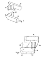
- FIG. 7 two side wall elements 30 and 31 are shown, which can be used with a vertical end to support the outer slope stones.
- These side wall elements have a rear wall section 32 which, as can be seen in FIG. 8, rests on the rear wall 16 of the slope stone 10 underneath and with two pins 33 arranged on both sides of the rear wall section extends over the rear wall of the slope stone below. Since the two pins extend over a substantial length of the rear wall section and rest with their long side against the rear wall of the slope stone below, there is no danger that the side wall element 30 will twist out of its intended position. This enables a stable vertical end closure for slope protection.
Abstract
Description
Die Erfindung betrifft einen vorgefertigten Hangstein aus Beton für den Aufbau einer begrünbaren Hangsicherung, welche durch Aufsetzen jeweils eines Hangsteins auf die Lücke zwischen zwei darunter im Abstand liegenden Hangsteinen gebildet ist, wobei der Hangstein aus einem in Draufsicht im wesentlichen viereckigen, umlaufend geschlossenen, oben und zumindest teilweise unten offenen Hohlkörper besteht, dessen waagerechte Ränder parallel zueinander verlaufen, und mit einem entlang der Frontwand sich in ganzer Breite anschließenden Bodensteg.The invention relates to a prefabricated slope stone made of concrete for the construction of a greenable slope protection, which is formed by placing a slope stone on the gap between two underlying slope stones, the slope stone from a substantially square, all-round closed, top and top view There is at least partially open hollow body below, the horizontal edges of which run parallel to one another, and with a floor web adjoining the full width along the front wall.
Ein derartiger Hangstein ist durch die DE-OS 29 44 550 bekannt und ist zwecks Einsparung von aus statischen Gründen vorgesehenen Zwischenwänden, wie sie durch die DE-PS 28 36 350 bekannt sind, mit verstärkten Eckbereichen versehen. Um dafür zu sorgen, daß das in der Lücke zwischen zwei Hangsteinen eingefüllte Erdreich unter einem flacheren Böschungswinkel ablagert, ist an die Unterseite der Frontwand ein Bodensteg angeschlossen, der keilförmig nach hinten verläuft. Eine aus derartigen Hangsteinen aufgebaute Hangsicherung hat in der Ansicht einen sehr hohen Betonflächenanteil, der noch dadurch vergrößert wird, daß die einzelnen Hangsteine an der Vorderwand und an einem an diese angrenzenden Bereich der beiden Seitenwände nach oben überstehende Wangen haben, die als Anschläge für den darüber abgelegten Hangstein dienen. Aufgrund dieser Ausbildung der Hangsteine ist es unvermeidlich, daß in der Ansicht die Betonwandfläche 60 und mehr % der gesamten Flächenansicht bedeckt. Dieser hohe Betonflächenanteil erhöht die Schallreflektion. Gleiches gilt auch für den Hangstein nach dem DE-GM 83 05 352.Such a slope stone is known from DE-OS 29 44 550 and is provided with reinforced corner areas for the purpose of saving partition walls provided for structural reasons, as are known from DE-PS 28 36 350. In order to ensure that the soil filled into the gap between two slope stones is deposited at a flatter slope angle, a floor bridge is connected to the underside of the front wall, which runs in a wedge shape to the rear. A slope protection constructed from such slope stones has a very high proportion of concrete surface in the view, which is further increased by the fact that the individual slope stones on the front wall and on an adjacent region of the two side walls have upwardly projecting cheeks, which act as stops for the person above stored hillside serve. Due to this formation of the slope stones, it is inevitable that in the view the concrete wall surface covers 60% and more of the entire surface view. This high proportion of concrete surface increases sound reflection. The same applies to the slope stone according to DE-GM 83 05 352.
Um den Betonflächenanteil einer bepflanzbaren Stützwand zu verringern, ist durch das DE-GM 81 15 371 ein rechteckrohrförmiger Hangstein mit offener Frontseite bekannt. Dieser Hangstein hat eine geschlossene Boden- und Deckfläche und wird ebenfalls auf Lücke verlegt. Die Tatsache, daß dieser Hangstein rechteckrohrförmig ausgebildet ist und eine über die gesamte Tiefe verlaufende Bodentlache sowie eine über den wesentlichen Teil der Tiefe verlaufende Deckfläche hat, wirkt sich als nachteilig aus, da die Hangsteine beim Verlegen einer geneigten Stützwand mit den Boden- und Deckflächen in den Hang nach hinten abfallend verlaufen. Wenn sich nämlich bei starkem anhaltendem Regen das Erdreich mit sehr viel Wasser anreichert, besteht die Gefahr, daß das sich im Erdreich sammelnde Wasser das Erdreich nach vorn ausspült, da das Erdreich wegen der fehlenden Frontfläche nach vorn nicht abgestützt ist. Dieses Ausspülen ist deshalb von Nachteil, da im vorderen Frontbereich für eine ausreichende Begrünung nicht mehr genügend Erdreich zur Verfügung steht und deshalb mangels Wurzelwerk auch die Begrünung das Erdreich nicht zurückhalten kann.In order to reduce the proportion of concrete surface of a support wall that can be planted, DE-GM 81 15 371 discloses a rectangular tubular slab with an open front. This slope stone has a closed floor and top surface and is also laid on a gap. The fact that this hillside is rectangular in shape and has a floor surface that runs over the entire depth and a cover surface that runs over the major part of the depth, which has a disadvantage because the slope stones fall backwards when the inclined support wall with the floor and cover surfaces slopes down into the slope . If, in the event of heavy, persistent rain, the soil is enriched with a great deal of water, there is a risk that the water collecting in the soil will wash the soil out to the front, since the soil is not supported to the front due to the lack of a front surface. This rinsing out is disadvantageous because there is no longer enough soil in the front area for sufficient greening and therefore, due to the lack of roots, the greening cannot hold back the soil.
Gleiches gilt auch für eine bepflanzbare Stützmauer, welche nach dem DE-GM 82 02 549 aus satzweise übereinander abgestellten Formsteinen und eingelegten, langgestreckten Tragplatten aufgebaut ist. Auch bei dem begrünbaren Boschungsbauwerk nach der DE-OS 34 02 314 ist ein Ausspülen der Frontpartien im geböschten Bereich vor den Formsteinen nicht vermeidbar. Diese als lange L-förmige Balken ausgeführten Böschungssteine werden derartig verlegt, daß der kürzere Schenkel in den Hang eingegraben ist, so daß der längere Schenkel wegen der Hangneigung nach außen ansteigend verläuft. Dadurch sammelt sich bei lang anhaltendem liegen in dem Eckbereich des L-tormigen Balkens so viel Flüssigkeit, daß das Erdreich seine innere Reibung verliert und lokal nach vorn herausgewaschen werden kann. Dieser Vorgang wird insbesondere dadurch begünstigt, daß am vorderen Ende des freiliegenden Schenkels keinerlei Barrieren sind, die ein Abfließen verhindern können. Da das Erdreich spitzwinklig bis zur vorderen Kante des freien Schenkels verläuft, steht im vorderen Bereich auch nicht genügend Erdreich zur Verfügung, um eine ausreichend dichte Bepflanzung zu ermöglichen, die mit ihrem Wurzelwerk das Erdreich zurückhalten könnte.The same also applies to a plantable retaining wall which, according to DE-GM 82 02 549, is constructed from molded blocks placed one above the other and inserted, elongated support plates. Even with the greening Boschungsbau after DE-OS 34 02 314 rinsing the front parts in the slope area in front of the shaped stones is unavoidable. These embankment stones, designed as long L-shaped beams, are laid in such a way that the shorter leg is buried in the slope, so that the longer leg rises outwards due to the slope. As a result, so much liquid collects in the corner area of the L-shaped bar that the soil loses its internal friction and can be locally washed out towards the front. This process is particularly favored by the fact that there are no barriers at the front end of the exposed leg which can prevent it from flowing off. Since the soil is at an acute angle to the front edge of the free leg, there is not enough soil available in the front area to enable sufficiently dense planting that could hold back the soil with its roots.
Der Erfindung liegt die Aufgabe zugrunde, einen vorgefertigten Hangstein der eingangs erwähnten Art derart zu schaffen, daß die sichtbare Betonfläche erheblich reduziert wird und außerdem die erwähnten Nachteile vermieden werden, welche bei gitterwandartigen Stützwerken durch Auswaschen von Erdreich entstehen können.The invention has for its object to provide a prefabricated slope of the type mentioned in such a way that the visible concrete surface is significantly reduced and also the mentioned disadvantages are avoided, which can arise in lattice wall-like support structures by washing out soil.
Diese Aufgabe wird erfindungsgemäß dadurch gelöst, daß die Frontwand einen vom oberen Hand aus auf etwa halbe Höhe nach unten und im wesentlichen über die gesamte Breite verlaufenden Ausschnitt hat, und daß sich der Bodensteg bis zu einer tiefe des Hangsteines erstreckt, die zumindest der Höhe der Seitenwand entspricht.This object is achieved in that the front wall has a cut from the upper hand down to about half the height and substantially over the entire width, and that the bottom web extends to a depth of the hillside, which is at least the height of Side wall corresponds.
Durch die Maßnahmen der Erfindung erhält man einen Hangstein, dessen sichtbare Betonfläche durch den Ausschnitt erheblich reduziert wird, wobei jedoch die dadurch bedingte statische Schwächung durch einen tiefer nach hinten gezogenen Bodensteg kompensiert wird. Durch den über den Bodensteg überstehenden Abschnitt der Frontwand erhält man auch im vordersten Bereich eine genügend hohe, stehende Erdmasse, die eine intensive Durchwurzelung zuläßt und dadurch gefestigt wird. Durch die hinter dem Bodensteg verbleibende Öffnung ist nach wie vor eine durchgehend gute Erdverbindung in dem in den Hangsteinen befindlichen Erdreich und zum Hang hin vorhanden. Damit ist eine intensive Verwurzelung der Pflanzen im Bereich der Hangsicherung und hinter der Hangsicherung möglich.Through the measures of the invention, a slope stone is obtained, the visible concrete surface of which is considerably reduced by the cutout, but the resulting static weakening is compensated for by a bottom web which is pulled further back. Due to the section of the front wall protruding from the footbridge, a sufficiently high, standing earth mass is obtained in the foremost area, which allows intensive rooting and is thereby strengthened. Due to the opening behind the floor bridge, there is still a good earth connection in the soil in the slope stones and towards the slope. This enables the plants to be deeply rooted in the area of the slope protection and behind the slope protection.
Nach einer Ausgestaltung der Erfindung ist vorgesehen, daß das Verhältnis Höhe : Breite : Tiefe des Hangsteins sich wie 1 : 2,75 : 2,5 verhält. Durch diese Maßnahme läßt sich der Anteil der sichtbaren Betonfläche einer begrünbaren Hangsicherung auf etwa 35 % der Gesamtfläche reduzieren, so daß es mit geeigneten Pflanzen möglich ist, den gesicherten Hang in seiner Gesamtheit als begrünte Fläche in Erscheinung treten zu lassen.According to one embodiment of the invention it is provided that the ratio of height: width: depth of the slope stone behaves as 1: 2.75: 2.5. By this measure, the proportion of the visible concrete surface of a greenable slope protection can be reduced to about 35% of the total area, so that it is possible with suitable plants to let the secured slope appear in its entirety as a green area.
Im Interesse einer optisch gefälligen Ansicht ist es vorgesehen, daß die tieferliegende Oberkante des Hangsteins im Ausschnitt über Kreis- oder Parabelbögen in die Seitenwand übergeht.In the interest of a visually pleasing view, it is provided that the lower-lying upper edge of the slope stone merges into the side wall in the cutout via circular or parabolic arches.
Damit bei einer konkav verlaufenden Sicherung der hintere Teil des Hangsteins moglichst stabil auf dem verdichteten Erdreich aufliegt, ist vorgesehen, daß sich der Bodensteg auch entlang der Seitenwände mit einer maximalen Breite von etwa 1/4 der Breite des Hangsteins erstreckt. Dieselbe Wirkung kann auch dadurch erreicht werden, daß die Seitenwände zur Rückwand verlaufend eine zunehmende Wandstärke haben. Der seitliche Bodensteg und/oder die zunehmende Wandstärke der Seitenwände dient auch der Erhöhung der statischen Festigkeit, insbesondere bei einer Verankerung der Hangsteine mit Geotextilien. Da zur zusätzlichen Hangsicherung die Möglichkeit geschaffen werden soll, die einzelnen Hangsteine mit Geotextilien im Hang zu verankern, sieht die Erfindung ferner vor, daß die obere und untere Innenkante zumindest im offenen Bodenbereich abgerundet sind.So that the rear part of the slope stone rests as stable as possible on the compacted soil in the case of a concave securing, it is provided that the floor bridge also extends along the side walls with a maximum width of approximately 1/4 the width of the slope stone. The same effect can also be achieved in that the side walls extending to the rear wall have an increasing wall thickness. The lateral floor bridge and / or the increasing wall thickness of the side walls also serves to increase the static strength, in particular when the slope stones are anchored with geotextiles. Since the possibility of anchoring the individual slope stones with geotextiles in the slope should be created for additional slope protection, the invention further provides that the upper and lower inner edges are rounded at least in the open floor area.
Um eine mit auf Lücke verlegten Hangsteinen aufgebaute Hangsicherung senkrecht abschließen zu können, sieht die Erfindung ferner vor, daß als Endabschluß ein Seitenwandelement Verwendung findet, das im Bereich der Rückwand eines darunter verlegten Hangsteines mit einem Rückwandabschnitt versehen ist, von welchem beiderseits Zapfen nach unten vorstehen, zwischen welche die darunter verlaufende Rückwand zu liegen kommt.In order to be able to vertically complete a slope safety device installed with gap stones, the invention further provides that a side wall element is used as the end closure, which is provided in the area of the rear wall of a slope stone laid underneath with a rear wall section, from which pins project downwards on both sides , between which the back wall running below comes to rest.
Die Vorteile und Merkmale der Erfindung ergeben sich auch aus der nachfolgenden Beschreibung von Ausführungsbeispielen in Verbindung mit den Ansprüchen und der Zeichnung. Es zeigen:
- Fig. 1 eine perspektivische Ansicht eines Hangsteins gemäß der Erfindung;
- Fig. 2 eine Draufsicht auf eine modifizierte Ausführungsform des Hangsteins gemäß Fig. 1;
- Fig. 3 eine Draufsicht auf eine weitere Modifikation des Hangsteins gemäß Fig. 1;
- Fig. 4 eine perspektivische Ansicht eines Hangsteins gemäß Fig. 1 mit abgerundeten Vorderkanten;
- Fig. 5 einen Schnitt durch eine Hangsicherung mit Hangsteinen gemäß der Erfindung längs dem Schnitt V-V der Fig. 6;
- Fig. 6 eine Vorderansicht einer Hangsicherung unter Verwendung des Hangsteins gemäß der Erfindung;
- Fig. 7 perspektivische Ansichten eines rechten und linken Seitenwandelementes zum Aufbau eines senkrechten Seitenabschlusses;
- Fig. 8 eine Seitenansicht eines senkrechten Seitenabschlusses mit einem Seitenwandelement zwischen zwei Hangsteinen.
- Figure 1 is a perspective view of a hillside according to the invention.
- FIG. 2 shows a plan view of a modified embodiment of the slope stone according to FIG. 1;
- FIG. 3 shows a plan view of a further modification of the slope stone according to FIG. 1;
- FIG. 4 shows a perspective view of a slope stone according to FIG. 1 with rounded front edges;
- 5 shows a section through a slope stabilization with slope stones according to the invention along the section VV of FIG. 6.
- 6 is a front view of a slope safety device using the slope stone according to the invention;
- 7 shows perspective views of a right and left side wall element for the construction of a vertical side termination;
- Fig. 8 is a side view of a vertical side end with a side wall element between two slope stones.
In Fig. 1 ist in perspektivischer Ansicht ein Hangstein 10 gemäß der Erfindung dargestellt, der aus einem oben offenen und unten zumindest teilweise offenen trogförmigen Betonkörper besteht, der an seiner Frontwand 11 mit einem tiefgezogenen Ausschnitt 17 versehen ist. Das Verhältnis von Höhe : Breite : Tiefe beträgt vorzugsweise etwa 1 : 2,75 : 2,5, wobei der Ausschnitt in der Frontwand auf bis etwa halbe Höhe der Frontwand nach unten verläuft. Dabei geht die tieferliegende Oberkante der Frontwand über Kreisbögen oder auch Parabelbögen in die Seitenwand 12 über.In Fig. 1, a
In Fig. 2 ist ein im wesentlichen der Fig. 1 entsprechender Hangstein 10.1 in Draufsicht dargestellt, wobei diese Draufsicht den Verlauf eines Bodensteges 14 zeigt, der parallel zur Frontwand 11 ausgerichtet ist. Dahinter befindet sich eine Öffnung 15, welche sich über die gesamte Breite der Bodenfläche erstreckt. Die Breite des Bodenstegs ist von der vorderseitigen Kante der Frontwand aus gemessen zumindest gleich der Höhe des Hangsteines bzw. einer Seitenwand. Die obere und untere Innenkante der Rückwand 16 ist mit einer Abrundung 18 versehen, die beim Verlegen der Hangsteine mit Geotextilien zur Hangsicherung ein Durchreiben der Geotextilien an einer scharfen Kante vermeiden soll.FIG. 2 shows a top view of a slope stone 10.1 corresponding essentially to FIG. 1, this top view showing the course of a
In Fig. 3 ist eine Draufsicht auf eine weitere Ausführungsform eines Hangsteines 10.2 gezeigt, bei welchem die zur Rückwand 16 verlaufenden Seitenwände eine zunehmende Wandstärke haben. Dadurch wird bei einem konvexen Verlauf der Hangsicherung gewährleistet, daß die Seitenwände übereinanderliegender Hangsteine eine sichere Auflage haben.3 shows a top view of a further embodiment of a slope stone 10.2, in which the side walls running to the
Die in Fig. 3 dargestellte Ausführungsform des Hangsteines läßt erkennen, daß sich ein seitlicher Bodensteg 21 entlang der Seitenwände bis zur Rückwand erstreckt. Diese seitlichen Stege sind auch bei der Ausführungsform gemäß Fig. 1 vorgesehen, so daß sich eine kleinere Öffnung 20 im hinteren Bereich des Hangsteines ergibt, die eine Erdverbindung zum darunterliegenden und dahinterliegenden Erdreich zuläßt. Obwohl bei der Ausführungsform gemäß Fig. 3 sowohl die seitlichen Stege 21 als auch die zunehmende Wandstärke der Seitenwände verwirklicht sind, können auch beide Maßnahmen separat an Hangsteinen angebracht sein. Die seitlichen Stege 21 sind insbesondere wünschenswert, wenn die Hangsicherung konkav verläuft, weil damit eine möglichst große Auflagefläche auf dem Erdreich im hinteren Bereich des Hangsteins gewährleistet ist.The embodiment of the slope stone shown in Fig. 3 shows that a
Die in Fig. 4 dargestellte Ausführungsform eines Hangsteins 10.3 unterscheidet sich von der Ausführungsform gemäß Fig. 1 lediglich dadurch, daß sowohl die senkrechten Vorderkanten als auch die Oberkante des Ausschnitts in der Frontwand abgerundet sind. Diese Abrundungen dienen im wesentlichen dazu, insbesondere bei konvex gekrümmten Hangsicherungen vorstehende Kanten zu vermeiden und einen optisch weicheren Eindruck zu bewirken.The embodiment of a slope stone 10.3 shown in FIG. 4 differs from the embodiment according to FIG. 1 only in that both the vertical front edges and the upper edge of the cutout are rounded in the front wall. These roundings essentially serve to avoid protruding edges, particularly in the case of convexly curved slope stabilizers, and to give a visually softer impression.
In Fig. 5 ist ein Schnitt durch eine Hangsicherung dargestellt, wie sie in Fig. 6 in Vorderansicht gezeigt ist. Aus der Darstellung gemäß Fig. 6 ist zu entnehmen, daß bei der Verlegung der Hangsteine auf Lücke die mit Schattenstrichen dargestellten Frontwände der einzelnen Steine nur noch einen sehr geringen Anteil der Gesamtansicht ausmachen. Bei einer Höhe des Hangsteines von 40 cm und einer Breite von 110 cm, wobei der Ausschnitt in der Frontwand sich bis auf die halbe Höhe erstreckt und über Viertelkreisbögen in die Seitenwand übergeht, ergibt sich ein sichtbarer Betonflächenanteil von etwa 35 % der Gesamtansicht. Aus dem Schnitt gemäß Fig. 5 kann man entnehmen, daß sich durch die Breite des Bodensteges 14 und die auf halber Höhe verlaufende Frontwand bei einem Neigungswinkel der Hangsicherung von 20° ein Böschungswinkel für das Erdreich in der Lücke zwischen jeweils zwei Hangsteinen von 40° bis 45° verwirklichen läßt. Die in diesem Bereich sichtbare Erdoberfläche gewährleistet eine gute Beregnung wegen der tiefergezogenen Frontwand, wobei ein Wasserstau in den Hangsteinen vermieden wird, da dieses durch die Offnungen 20 im Bodenbereich über die horizontal liegende Bodenfläche abfließen kann. Durch die halb hochgezogene Frontwand ergibt sich jeweils am Fuß des geböschten Erdreichs genügend Erdmasse, um auch in dem von dem Tageslicht besonders intensiv beschienenen vorderen Teil des Erdreichs genügend Erde für eine sichere Durchwurzelung und Verwurzelung von Pflanzen.FIG. 5 shows a section through a slope safety device, as is shown in a front view in FIG. 6. From the representation according to FIG. 6 it can be seen that when the slope stones are laid on a gap, the front walls of the individual stones shown with shadows make up only a very small proportion of the overall view. With a height of the slope stone of 40 cm and a width of 110 cm, whereby the cut-out in the front wall extends to half the height and merges into the side wall via quarter arcs, there is a visible proportion of concrete surface of around 35% of the overall view. From the section according to FIG. 5 it can be seen that through the width of the
Um die Hangsteine in den Hang hinein zu verankern, können um die Rückwand 16, insbesondere im Bereich der Abrundung 18, Geotextilien 30 gezogen werden, die in herkömmlicher Weise in den rückwärtigen Hang eingebracht und unter Verdichtung des Erdreiches verlegt werden.In order to anchor the slope stones into the slope, geotextiles 30 can be drawn around the
In Fig. 7 sind zwei Seitenwandelemente 30 und 31 dargestellt, die bei einem senkrechten Endabschluß zur Abstützung der äußeren Hangsteine Verwendung finden können. Diese Seitenwandelemente haben einen Rückwandabschnitt 32, der, wie aus Fig. 8 hervorgeht, auf der Rückwand 16 des darunterliegenden Hangsteines 10 aufliegt und mit zwei beiderseits des Rückwandabschnitts angeordneten Zapfen 33 über die Rückwand des darunterliegenden Hangsteines greist. Da die beiden Zapfen sich über eine wesentliche Länge des Rückwandabschnittes erstrecken und mit ihrer Längsseite an der Rückwand des darunterliegenden Hangsteines anliegen, besteht keine Gefahr, daß sich das Seitenwandelement 30 aus seiner vorgesehenen Lage heraus verdreht. Damit wird ein stabiler senkrechter Endabschluß für eine Hangsicherung ermöglicht.In Fig. 7 two
Claims (8)
Applications Claiming Priority (2)
| Application Number | Priority Date | Filing Date | Title |
|---|---|---|---|
| DE3530049A DE3530049C2 (en) | 1985-08-22 | 1985-08-22 | Prefabricated concrete slab |
| DE3530049 | 1985-08-22 |
Publications (1)
| Publication Number | Publication Date |
|---|---|
| EP0212357A1 true EP0212357A1 (en) | 1987-03-04 |
Family
ID=6279117
Family Applications (1)
| Application Number | Title | Priority Date | Filing Date |
|---|---|---|---|
| EP86110431A Ceased EP0212357A1 (en) | 1985-08-22 | 1986-07-29 | Prefabricated concrete suspension stone |
Country Status (2)
| Country | Link |
|---|---|
| EP (1) | EP0212357A1 (en) |
| DE (1) | DE3530049C2 (en) |
Cited By (11)
| Publication number | Priority date | Publication date | Assignee | Title |
|---|---|---|---|---|
| FR2627525A1 (en) * | 1988-02-23 | 1989-08-25 | Communeau Roger | Block for retaining wall construction - has base, side and at least one end wall, with interlocking formations for connection of superposed blocks |
| EP0379888A1 (en) * | 1989-01-25 | 1990-08-01 | Felix Paul Dr. Jaecklin | Building element for cellular constructions with a loose material filling |
| DE3920514A1 (en) * | 1989-06-22 | 1991-01-10 | Munderkingen Betonwerke | Concrete prefabricated slope block - has coarse-mesh plastics anchoring grille grouted into rear wall |
| GB2261244A (en) * | 1991-11-06 | 1993-05-12 | Vidal Henri Brevets | Facing element and facing system |
| EP0637648A1 (en) * | 1993-07-30 | 1995-02-08 | Semmelrock Kg | Retaining block |
| US5474405A (en) * | 1993-03-31 | 1995-12-12 | Societe Civile Des Brevets Henri C. Vidal | Low elevation wall construction |
| US5487623A (en) * | 1993-03-31 | 1996-01-30 | Societe Civile Des Brevets Henri C. Vidal | Modular block retaining wall construction and components |
| US5624211A (en) * | 1993-03-31 | 1997-04-29 | Societe Civile Des Brevets Henri C. Vidal | Modular block retaining wall construction and components |
| US5797706A (en) | 1993-06-24 | 1998-08-25 | Societe Civile Des Brevets Henri Vidal | Earth structures |
| US5839855A (en) * | 1995-08-18 | 1998-11-24 | Societe Civile Des Brevets Henri C. Vidal | Facing element for a stabilized earth structure |
| GB2347960A (en) * | 1999-02-11 | 2000-09-20 | Earth Wall Systems Ltd | Biodegradable building element |
Families Citing this family (3)
| Publication number | Priority date | Publication date | Assignee | Title |
|---|---|---|---|---|
| DE3913335A1 (en) * | 1989-04-22 | 1990-10-25 | Rolf Hoelzer | WALL |
| DE3932493A1 (en) * | 1989-09-28 | 1991-04-11 | Volker Dipl Ing Hansen | Construction steep embankment covered with plants - uses base elements with surface strip between bottom and ground surfaces |
| CN105484199B (en) * | 2015-12-28 | 2017-09-22 | 陈桂腾 | A kind of dam configuration and its construction method |
Citations (6)
| Publication number | Priority date | Publication date | Assignee | Title |
|---|---|---|---|---|
| FR345512A (en) * | 1904-08-04 | 1904-12-02 | Alfred John Eggleton | Flower pots |
| EP0013535A1 (en) * | 1979-01-04 | 1980-07-23 | Rolf Scheiwiller | Set of retaining-wall elements and its application |
| DE3025870A1 (en) * | 1980-07-08 | 1982-02-04 | Georg Zürich Stulz | Vegetation supporting retaining wall hollow block - is trough shaped with sloping interfacing lengthways sides |
| FR2545128A1 (en) * | 1983-04-26 | 1984-11-02 | Sotubema | Construction block and structure consisting of such blocks |
| FR2550812A2 (en) * | 1982-01-05 | 1985-02-22 | Auric Lucien | Mechanical (interlocking) wall. |
| DE3344974A1 (en) * | 1983-12-13 | 1985-06-20 | Kronimus & Sohn Betonsteinwerk und Baugeschäft GmbH & Co KG, 7551 Iffezheim | BOOTHING STONE AND METHOD FOR BUILDING UP A HANGING FASTENING THEREFORE |
Family Cites Families (5)
| Publication number | Priority date | Publication date | Assignee | Title |
|---|---|---|---|---|
| DE7809229U1 (en) * | 1978-07-13 | Tubag Trass-, Zement- Und Steinwerke Gmbh, 5473 Kruft | Embankment stone | |
| DE2519232C3 (en) * | 1975-04-30 | 1980-05-29 | Herwig 7031 Hildrizhausen Neumann | Plantable retaining wall |
| CH591604A5 (en) * | 1975-11-19 | 1977-09-30 | Jaecklin Felix Paul | |
| CH638853A5 (en) * | 1978-06-13 | 1983-10-14 | Jaecklin Felix Paul | Structural element for fabricating structures and use of the same for fabricating walls |
| CH645148A5 (en) * | 1979-09-25 | 1984-09-14 | Kalbermatten Otto Zementwaren | Embankment block for the construction of means for stabilising slopes |
-
1985
- 1985-08-22 DE DE3530049A patent/DE3530049C2/en not_active Expired - Fee Related
-
1986
- 1986-07-29 EP EP86110431A patent/EP0212357A1/en not_active Ceased
Patent Citations (6)
| Publication number | Priority date | Publication date | Assignee | Title |
|---|---|---|---|---|
| FR345512A (en) * | 1904-08-04 | 1904-12-02 | Alfred John Eggleton | Flower pots |
| EP0013535A1 (en) * | 1979-01-04 | 1980-07-23 | Rolf Scheiwiller | Set of retaining-wall elements and its application |
| DE3025870A1 (en) * | 1980-07-08 | 1982-02-04 | Georg Zürich Stulz | Vegetation supporting retaining wall hollow block - is trough shaped with sloping interfacing lengthways sides |
| FR2550812A2 (en) * | 1982-01-05 | 1985-02-22 | Auric Lucien | Mechanical (interlocking) wall. |
| FR2545128A1 (en) * | 1983-04-26 | 1984-11-02 | Sotubema | Construction block and structure consisting of such blocks |
| DE3344974A1 (en) * | 1983-12-13 | 1985-06-20 | Kronimus & Sohn Betonsteinwerk und Baugeschäft GmbH & Co KG, 7551 Iffezheim | BOOTHING STONE AND METHOD FOR BUILDING UP A HANGING FASTENING THEREFORE |
Cited By (13)
| Publication number | Priority date | Publication date | Assignee | Title |
|---|---|---|---|---|
| FR2627525A1 (en) * | 1988-02-23 | 1989-08-25 | Communeau Roger | Block for retaining wall construction - has base, side and at least one end wall, with interlocking formations for connection of superposed blocks |
| EP0379888A1 (en) * | 1989-01-25 | 1990-08-01 | Felix Paul Dr. Jaecklin | Building element for cellular constructions with a loose material filling |
| DE3920514A1 (en) * | 1989-06-22 | 1991-01-10 | Munderkingen Betonwerke | Concrete prefabricated slope block - has coarse-mesh plastics anchoring grille grouted into rear wall |
| GB2261244B (en) * | 1991-11-06 | 1995-09-20 | Vidal Henri Brevets | Earth structure and facing element therefor |
| GB2261244A (en) * | 1991-11-06 | 1993-05-12 | Vidal Henri Brevets | Facing element and facing system |
| US5474405A (en) * | 1993-03-31 | 1995-12-12 | Societe Civile Des Brevets Henri C. Vidal | Low elevation wall construction |
| US5487623A (en) * | 1993-03-31 | 1996-01-30 | Societe Civile Des Brevets Henri C. Vidal | Modular block retaining wall construction and components |
| US5507599A (en) * | 1993-03-31 | 1996-04-16 | Societe Civile Des Brevets Henri C. Vidal | Modular block retaining wall construction and components |
| US5624211A (en) * | 1993-03-31 | 1997-04-29 | Societe Civile Des Brevets Henri C. Vidal | Modular block retaining wall construction and components |
| US5797706A (en) | 1993-06-24 | 1998-08-25 | Societe Civile Des Brevets Henri Vidal | Earth structures |
| EP0637648A1 (en) * | 1993-07-30 | 1995-02-08 | Semmelrock Kg | Retaining block |
| US5839855A (en) * | 1995-08-18 | 1998-11-24 | Societe Civile Des Brevets Henri C. Vidal | Facing element for a stabilized earth structure |
| GB2347960A (en) * | 1999-02-11 | 2000-09-20 | Earth Wall Systems Ltd | Biodegradable building element |
Also Published As
| Publication number | Publication date |
|---|---|
| DE3530049A1 (en) | 1987-02-26 |
| DE3530049C2 (en) | 1994-08-11 |
Similar Documents
| Publication | Publication Date | Title |
|---|---|---|
| EP0430890B1 (en) | Wall element for dry construction of walls, building system for securing slopes and slope wall built with the building system | |
| EP0212357A1 (en) | Prefabricated concrete suspension stone | |
| DE7824776U1 (en) | ELEMENT FOR SLOPE SECURITY | |
| DE2537408A1 (en) | BOESCHUNGSTEIN FOR THE CREATION OF PLANTABLE RETAINING WALLS | |
| EP0047718B1 (en) | Hollow block for constructing bank acclivities | |
| CH682164A5 (en) | ||
| DE2519232A1 (en) | BUILDING ELEMENT SYSTEM FOR CREATING PLANTABLE WALLS | |
| EP0322667A1 (en) | Method for building a wall, construction element and connection slab for applying the method, and wall built by the method | |
| EP0102637B1 (en) | Slope element | |
| DE2724224C3 (en) | Drainage element for the production of drainage lines designed as a hollow wall as well as a soil drainage system formed from drainage elements | |
| EP0469008B1 (en) | A wall | |
| EP0024500B1 (en) | Concrete building element | |
| DE1965752U (en) | GRID TILE MADE OF PLASTIC. | |
| EP0286957B1 (en) | Vegetation-sustaining noise barrier | |
| DE3423566A1 (en) | Noise protection screen | |
| DE3516969C2 (en) | Plantable support structure | |
| DE8532773U1 (en) | Large-format shaped concrete block for the erection of vertical, plantable visible and / or soundproof walls | |
| DE2837126A1 (en) | Paving slab for placing on lawn - has vertical hooks projecting from underside to anchor slab in position | |
| DE4126657C1 (en) | Vegetative sound barrier with longitudinal walls - has each wall of longitudinal elements with vertical, tightly packed willow braches | |
| EP0212036A1 (en) | Interconnecting stone for lawn | |
| DE7916819U1 (en) | CONSTRUCTION ELEMENT FOR THE PRODUCTION OF WALLS WITH A FRAMEWORK-BASED STRUCTURE THAT CAN BE FILLED WITH EARTH | |
| AT520177B1 (en) | Drywall and intermediate stone therefor | |
| DE4240229C2 (en) | Amphibian guide wall | |
| DE2908578A1 (en) | Banking or noise screen walling concrete element - has lengthways bars linking ends of Z=shaped cross stem arms | |
| DE3712710A1 (en) | Noise protection wall capable of supporting plants |
Legal Events
| Date | Code | Title | Description |
|---|---|---|---|
| PUAI | Public reference made under article 153(3) epc to a published international application that has entered the european phase |
Free format text: ORIGINAL CODE: 0009012 |
|
| AK | Designated contracting states |
Kind code of ref document: A1 Designated state(s): AT CH FR GB IT LI |
|
| 17P | Request for examination filed |
Effective date: 19870821 |
|
| 17Q | First examination report despatched |
Effective date: 19881219 |
|
| STAA | Information on the status of an ep patent application or granted ep patent |
Free format text: STATUS: THE APPLICATION HAS BEEN REFUSED |
|
| 18R | Application refused |
Effective date: 19900415 |