EP0212078B1 - Vorrichtung zur Messung des Dickenprofils von gewalzten Bändern - Google Patents
Vorrichtung zur Messung des Dickenprofils von gewalzten Bändern Download PDFInfo
- Publication number
- EP0212078B1 EP0212078B1 EP86106795A EP86106795A EP0212078B1 EP 0212078 B1 EP0212078 B1 EP 0212078B1 EP 86106795 A EP86106795 A EP 86106795A EP 86106795 A EP86106795 A EP 86106795A EP 0212078 B1 EP0212078 B1 EP 0212078B1
- Authority
- EP
- European Patent Office
- Prior art keywords
- slit diaphragm
- radiation
- switch
- inclusive
- processing instrument
- Prior art date
- Legal status (The legal status is an assumption and is not a legal conclusion. Google has not performed a legal analysis and makes no representation as to the accuracy of the status listed.)
- Expired - Lifetime
Links
- 238000005259 measurement Methods 0.000 title claims description 16
- 230000033001 locomotion Effects 0.000 claims abstract description 22
- 238000010521 absorption reaction Methods 0.000 claims abstract description 14
- 230000005855 radiation Effects 0.000 claims description 72
- 238000012545 processing Methods 0.000 claims description 26
- 238000006073 displacement reaction Methods 0.000 claims description 13
- 238000012937 correction Methods 0.000 claims description 12
- 238000005096 rolling process Methods 0.000 claims description 6
- 238000011156 evaluation Methods 0.000 claims description 2
- 238000000034 method Methods 0.000 claims description 2
- 230000000149 penetrating effect Effects 0.000 claims 2
- 238000013461 design Methods 0.000 claims 1
- 239000002184 metal Substances 0.000 abstract description 7
- 238000001514 detection method Methods 0.000 description 3
- 230000000694 effects Effects 0.000 description 2
- 238000004519 manufacturing process Methods 0.000 description 2
- 230000004888 barrier function Effects 0.000 description 1
- 230000009286 beneficial effect Effects 0.000 description 1
- 230000005540 biological transmission Effects 0.000 description 1
- 238000010276 construction Methods 0.000 description 1
- 230000001419 dependent effect Effects 0.000 description 1
- 238000011161 development Methods 0.000 description 1
- 230000018109 developmental process Effects 0.000 description 1
- 238000009826 distribution Methods 0.000 description 1
- 230000003760 hair shine Effects 0.000 description 1
- 230000002452 interceptive effect Effects 0.000 description 1
- 230000035945 sensitivity Effects 0.000 description 1
- 238000003860 storage Methods 0.000 description 1
Images
Classifications
-
- G—PHYSICS
- G01—MEASURING; TESTING
- G01B—MEASURING LENGTH, THICKNESS OR SIMILAR LINEAR DIMENSIONS; MEASURING ANGLES; MEASURING AREAS; MEASURING IRREGULARITIES OF SURFACES OR CONTOURS
- G01B15/00—Measuring arrangements characterised by the use of electromagnetic waves or particle radiation, e.g. by the use of microwaves, X-rays, gamma rays or electrons
- G01B15/02—Measuring arrangements characterised by the use of electromagnetic waves or particle radiation, e.g. by the use of microwaves, X-rays, gamma rays or electrons for measuring thickness
- G01B15/025—Measuring arrangements characterised by the use of electromagnetic waves or particle radiation, e.g. by the use of microwaves, X-rays, gamma rays or electrons for measuring thickness by measuring absorption
Definitions
- the invention relates to a device for measuring the thickness profile of rolled metal sheets and sheet metal strips with an X-ray tube, with a slit diaphragm lying in front of it and rotating about its center, with several slits and with a fixed distance along the line at a distance in front of the slit diaphragm Radiation of the x-ray tube aligned radiation receivers and an outlet roller table for the sheet metal to be measured, located in the beam path between the x-ray tube and the radiation receivers, whose rolling direction is perpendicular to the line of the radiation receiver and whose width extends along the line of the permanently installed radiation receiver and with one to the radiation receiver and a position sensor of the slot position connected processing device for determining the radiation absorption and the assignment to the thicknesses of the sheet metal strip and the measuring points distributed over the width of the sheet metal strip od he measuring ranges, which processing device is connected to a display device.
- a device for thickness profile measurement is known from DE-A 3 140 714. This has the disadvantage that only relatively imprecise measurements can be carried out. Because of the size of the receivers, it is not possible to divide the sheet metal strip to be measured into narrow areas, between which there are no unmeasured areas. Another disadvantage is that the number of radiation receivers used is very large, which makes the device complicated and expensive.
- Such a slit diaphragm has a large mass, which is why only a few measured values can be determined per second, because the slit diaphragm can only be moved oscillating very slowly. This large mass also causes oscillating movements on the entire frame, as a result of which narrow measuring ranges are not possible, particularly in the case of larger distances between the radiation source and the radiation receiver.
- a rotating slit diaphragm with extremely narrow slits lying close to the radiation source is described in DE-A 3 425 295 published on March 20, 1986.
- the central axis of each slot always coincides with the beam direction because of the rotational movement of the slit diaphragm around the radiation source.
- the device according to DE-A 3 425 295 therefore has the high local resolution required for use in rolling mills.
- a disadvantage is the large number of slots, of which only about a tenth is in use at any moment and is irradiated. The extremely precise manufacture of the narrow slots is very expensive. Another disadvantage is that small mistakes in slot making are inevitable. Small errors have such a great effect at the large distances to the radiation receivers that they have to be taken into account in the evaluation by means of a correction factor.
- 150 slits with a width of approx. 1 mm are necessary for the slit diaphragm and the row of radiation receivers contains 14 radiation receivers, so that 150 times 14 correction factors arise, the consideration of which causes a great deal of computing effort in the processing device.
- Another disadvantage is that the device has to be re-calibrated very often in the rough rolling mill conditions and the required extremely precise measurements, with each correction factor having to be determined anew.
- the present invention has for its object to provide a device for measuring the thickness profile of rolled metallic strips, which manages to maintain a high local resolution of the measurements with an easy to manufacture slit diaphragm and a small and easy to calibrate processing device, which also Measurement results are measured at an exact constant distance from the edge of the belt.
- the slit diaphragm only needs to be moved back and forth by the extremely slight rotation of less than 5 ° because it sits as close as possible near the x-ray tube and at the same time the radiation receivers are relatively far away from the x-ray tube and the slit diaphragm at the same time is provided with a larger number of slots.
- the overall length of the slit diaphragm is relatively short, which means that its mass is also small. Due to the small rotation of less than 5 ° there is only a relatively small rotation speed needed. This has the consequence that only small mass forces arise in the reversal points of the movement. The low mass forces can even be absorbed by the foundations of the device without any mass balancing, without any disturbing vibrations being noticeable. It is of course also possible to balance the mass in the form of a mass which is moved counter to the rotational movement of the slit diaphragm and whose movement is reversed by a gearwheel z. B. is derived from the movement of the slit diaphragm.
- the size of the rotary movement can be reduced even further if the number of slots in the slot diaphragm is increased. It is expedient if a slot is also provided in the slit diaphragm for each radiation receiver. The range of rotation of a slot can also extend over two or more radiation receivers.
- the thickness of narrow strips of the tape lying exactly in the direction of travel of the tape is measured if the rotation of the slit diaphragm takes place in steps with intermediate dwell times, in which the slit diaphragm stands still and the measured value recording of the processing device is switched on during the dwell time between two steps of the slit diaphragm.
- the measured value recording is switched on and off by a switch or a contactless switching element which is attached to the drive of the slit diaphragm, most suitably on a shaft, which rotates exactly one turn per step of the slit diaphragm.
- the switch can e.g. B. by a suitably designed cam on the shaft or contactless by z. B. reflected light beams can be operated in a known manner.
- the rotation of the slit diaphragm is only so large that less than 95% of the effective length of the radiation receiver is swept by the beam and narrow regions are omitted at the edges of the radiation receiver.
- These narrow areas serve as a balancing reserve if z. B. result from thermal expansion small differences in position between the slit diaphragm and the radiation receivers. This ensures that the first and the last measuring range are still completely on the radiation receiver.
- Another possibility to compensate for small differences in position is when the beginning of the first measuring range of a radiation receiver in the passage begins in the small space between the radiation receivers which is ineffective for radiation and the measured value of the first measuring range by a corresponding correction factor for the radiation falling into the ineffective space is taken into account. It is beneficial if this correction factor is used as often as possible, e.g. B. is redetermined after each strip run by a calibration measurement. However, it should be redetermined every 2 hours at the latest. If the space z. B. 6 mm wide, so differences in position that cause a deflection of the beam up to 6 mm from the target position can be compensated.
- the slit diaphragm has the shape of a small segment of a circular ring. It is entirely sufficient if the slit diaphragm is limited to the tenth part of a circle and 15 narrow slits are worked into the slit diaphragm at the same distance from one another, which are radially in the direction of the imaginary center of the circular ring.
- the imaginary central axis of the X-ray tube represents the axis of rotation of the annulus.
- the beam passing through a slit strikes the radiation receiver associated with this slit approximately 2 m from the slit diaphragm, which can have a length of approximately 15.
- the back and forth movement of the beam takes place only over the 15 cm length of the radiation receiver.
- the adjacent beam from the adjacent slot scans the adjacent radiation receiver.
- the reciprocating rotary movement of the slit diaphragm takes place through an angle of rotation which is less than 3 ° .
- the strip to be measured lies in such a way that the edge of the strip lies within a measuring range, then this measuring range cannot be used for specifying the thickness profile. It is then advantageous if the processing of the measured values in the processing device is suppressed so that the measured value is suppressed for the thickness profile, which is at the beginning of the run after the last measured value, which does not indicate absorption and also the measured value which is suppressed towards the end of the Pass before the first measured value, which has no absorption.
- the calibration of the device is carried out during operation in the short pauses between two belt passes in such a way that measurement is carried out without a belt to be measured in the device and an average value is calculated from the measured values of the radiation receivers and so each individual measured value of a measuring range is provided with a correction factor is that the product measured value times correction factor gives the mean value and the correction factors thus formed are stored in the processing device and are used for processing the measured values obtained with the strip being irradiated.
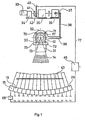
- the X-ray tube 11 is surrounded by a shield 12 in a ring.
- the shield 12 has a window 13 through which a beam 14 shines in the direction of the radiation receivers 15-29.
- the radiation receivers 15-29 are on egg ner arranged circular line, the center of which coincides with the center 30 of the X-ray tube.
- the slit diaphragm 31 In front of the window 13 is the slit diaphragm 31, which is moved back and forth around the center 30 of the X-ray tube 11 by less than 3 ° in both directions of rotation.
- a bracket 32 is attached, which at points 70 to 73 by z. B. roles is stored.
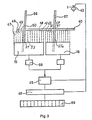
- the slit diaphragm 31 is driven for the reciprocating pivoting movement by the motor 33, which, for. B. can be a three-phase motor.
- the speed of the motor 33 is reduced in the gear 34 and the stepping gear 35 is driven with the reduced speed.
- the step gear 35 divides the continuous rotary motion into a stepwise rotary motion. A 60 millisecond rotation is followed by a 70 millisecond standstill. This is done in a known manner within the stepper by z. B. causes a suitably designed cam.
- the pendulum gear 36 is driven by the step gear 35. In this, the rotary movement is converted in a known manner into a pendulum movement, which is transmitted to the slit diaphragm 31 via the lever 37, the rod 38 and the lever 39 connected to the bracket 32.
- the pendulum gear 36 reverses the movement after every 14 steps of the stepping gear 35.
- the radiation receivers 15-29 are 150 mm long and arranged on a circle within the belt 40 to be examined between 2 rollers of an unillustrated outlet roller table of a rolling mill so that these are all at the same distance from the center 30 of the X-ray tube 11.
- the X-ray tube is arranged above the run-out roller table.
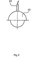
- the gear ratios in the gearboxes are coordinated with one another in such a way that the shaft 41 makes exactly one revolution while the slit diaphragm moves one step further and remains between the steps.
- a switch 43 is mounted above a cam 42 which is fixed on the shaft 41. This course disc switches the switch 43 z. B. during one half of the rotation and off during the other half.
- This switch 43 can be operated mechanically, but it can also be non-contact z. B. be operated with the help of an interrupted light beam when z. B. the upper part of the cam disc in FIG. 2 interrupts the light beam of a light barrier and the lower part with a smaller radius allows the light beam to pass, thereby triggering the switching functions.
- the switch 43 is set so that there is a switch at the beginning and at the end of the rest periods lying between the steps of the step transmission 35.
- This switching information from the switch 43 is given to the line 44 to a displacement sensor 45.
- the displacement sensor is also connected to each of the radiation receivers 15-29 via an amplifier 68.
- the output of the displacement sensor 45 is connected to the processing device 46, the output of which is in turn connected to the display device 69.
- the switch 43 by means of its signal going through the path encoder 45 to the processing device 46, has the effect that all measurement signals coming from the radiation receivers 15 to 29 during the movement of the slit diaphragm 31 are suppressed and only the measurement signals arriving in the pauses between the steps are processed.
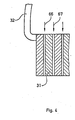
- the radiation receiver 15 shown in FIG. 3 contains 13 measuring ranges, which are indicated by dashed lines and are designated by 47 to 59. From the radiation receiver 16 lying next to it, the first measuring ranges are denoted by 62 to 65 a.
- the beam 66 let through from the slit diaphragm 31 is located in the measuring area 51, while the next slit of the slit diaphragm 31 passes a beam 67 onto the measuring area 65 a of the following radiation receiver 16.
- the beam 66 passes through the measuring ranges from the radiation receiver 15 towards the radiation receiver 16 and then back again in 4 seconds. If the beam 66 e.g. B. stands on the measuring area 51 during the pause between the steps, the beam is weakened according to the thickness of the strip 40 to be penetrated. A current which is dependent on the intensity of the beam 66 is generated in the radiation receiver 15. This current flows via the amplifier 68 to the displacement sensor 45 in the processing device 46, where it is processed into a measurement variable corresponding to the thickness of the band 40. This measured variable is passed on to the display device. In addition to the display device, other devices such. B. connected to correct the rolling process.
- the switch 43 swings in its z. B. interrupted position by its connection to the processing device that all of the radiation signals 15 - 29 coming measurement signals are suppressed when z. B. the slit diaphragm 31 is moved one step further during a half revolution of the shaft 41. The measurement signals are only processed again when the switch is in the closed position during the other half of the rotation of the shaft 41.
- the number of power interruptions of the switch 43 is counted in the travel encoder 45.
- the amplifier 68 superimposes a detection signal on the output current which differs from the detection signals of the other amplifiers which are connected downstream of the other radiation receivers. From the detection signal, the path encoder 45 recognizes which radiation receiver the measurement variable is to be assigned to, and from the number of interruptions in the switch 43 counted, the path encoder recognizes in which measurement range of the radiation receiver concerned the beam is currently located.
- the displacement sensor 45 sends the measured variable together with a signal assigned to each measuring range to the processing device 46.
- the values of the individual measuring ranges can be fed to a display device 69, the display screen of which is also divided into the same number of measuring ranges. Each of the measuring ranges 47 to 61 corresponds analogously and in terms of position to a narrow strip on the screen of the display device 69. These strips are indicated by dashed lines.
- the values of the thickness of the band 40 can be displayed digitally, but they can also be displayed as dots on the screen, the height of the dots corresponding to the size of the thickness.
- the points can also be connected to a curve. Any other display device can also be connected.
- the counting for the assignment of the measuring ranges is started anew in the exemplary embodiment 45 after every 14th step.
- radiation receivers are, for. B. plastic scintillators, which are connected in a known manner photomultiplier and amplifier or counting devices.
- the distance from the center 30 of the X-ray tube 11 to the radiation receivers 15 to 29 is 3820 mm.
- the distance from the belt to the central radiation receiver is 1200 mm.
- the distance from the center of the slit diaphragm 31 to the center 30 of the X-ray tube 11 is 530 mm.
- the slit diaphragm 31 has a thickness in the beam direction of 180 mm.
- Fifteen slots are provided on the slit diaphragm 31. Each slot is 1.2 mm wide and is about 21 mm apart from the next slot.
- the two large boundary surfaces of the slots are plane-parallel in the example shown. Even greater accuracy would be achieved if these delimiting surfaces were somewhat wedge-shaped in relation to each other in the direction of the beam. With the device, thickness fluctuations of the strip of less than 2 parts per thousand are measured.
- a precise determination of the band edge takes place e.g. B. if, according to FIG. 3, the beam 66 first strikes the measuring area 47 of the radiation receiver 15. No absorption takes place in this position. A partial absorption takes place at the next measuring range 48. Full absorption takes place in measuring range 49 and the following measuring ranges. If e.g. B. the measuring range 48 gives a measured value, the difference to the measured value of the measuring range 47 z. B. 40% of the difference between the measured values of the measuring ranges 47 and 49 results in the band edge from the measuring range 47 to the right by 40% of the width of a measuring range. The difference is z. B. 30%, the distance is 30% of the width to the right.
- This distance counts from the right side of the measuring range 47 to the right in the direction of the measuring range 49.
- the storage of the measured values, the difference between the measured values and the resulting position of the strip edge takes place in a manner known per se in the processing device 46 which contains a computer.
Landscapes
- Physics & Mathematics (AREA)
- Electromagnetism (AREA)
- General Physics & Mathematics (AREA)
- Length-Measuring Devices Using Wave Or Particle Radiation (AREA)
- Analysing Materials By The Use Of Radiation (AREA)
- Length Measuring Devices With Unspecified Measuring Means (AREA)
Priority Applications (1)
| Application Number | Priority Date | Filing Date | Title |
|---|---|---|---|
| AT86106795T ATE58789T1 (de) | 1985-08-23 | 1986-05-17 | Vorrichtung zur messung des dickenprofils von gewalzten baendern. |
Applications Claiming Priority (2)
| Application Number | Priority Date | Filing Date | Title |
|---|---|---|---|
| DE3530109 | 1985-08-23 | ||
| DE19853530109 DE3530109A1 (de) | 1985-08-23 | 1985-08-23 | Vorrichtung zur messung des dickenprofils von gewalzten baendern |
Publications (2)
| Publication Number | Publication Date |
|---|---|
| EP0212078A1 EP0212078A1 (de) | 1987-03-04 |
| EP0212078B1 true EP0212078B1 (de) | 1990-11-28 |
Family
ID=6279154
Family Applications (1)
| Application Number | Title | Priority Date | Filing Date |
|---|---|---|---|
| EP86106795A Expired - Lifetime EP0212078B1 (de) | 1985-08-23 | 1986-05-17 | Vorrichtung zur Messung des Dickenprofils von gewalzten Bändern |
Country Status (6)
| Country | Link |
|---|---|
| US (1) | US4759046A (enExample) |
| EP (1) | EP0212078B1 (enExample) |
| JP (1) | JPH0739951B2 (enExample) |
| AT (1) | ATE58789T1 (enExample) |
| CA (1) | CA1255398A (enExample) |
| DE (2) | DE3530109A1 (enExample) |
Families Citing this family (5)
| Publication number | Priority date | Publication date | Assignee | Title |
|---|---|---|---|---|
| US4928257A (en) * | 1988-01-25 | 1990-05-22 | Bethlehem Steel Corporation | Method and apparatus for monitoring the thickness profile of a strip |
| DE19722482A1 (de) * | 1997-05-28 | 1998-12-03 | Siemens Ag | Materialprüfanlage |
| GB2355071A (en) * | 1999-10-08 | 2001-04-11 | Cintex Ltd | Non-contact volume measurement |
| DE19950254C2 (de) | 1999-10-18 | 2003-06-26 | Ims Messsysteme Gmbh | Verfahren zur Bestimmung eines Dickenquerprofils und des Dickenlängsprofils eines laufenden Materialbandes |
| US6347131B1 (en) | 1999-11-02 | 2002-02-12 | Cintex Limited | Non-contact volume measurement |
Family Cites Families (10)
| Publication number | Priority date | Publication date | Assignee | Title |
|---|---|---|---|---|
| US3866047A (en) * | 1968-08-23 | 1975-02-11 | Emi Ltd | Penetrating radiation examining apparatus having a scanning collimator |
| US3790799A (en) * | 1972-06-21 | 1974-02-05 | American Science & Eng Inc | Radiant energy imaging with rocking scanning |
| GB1552224A (en) * | 1975-05-10 | 1979-09-12 | Heath Gloucester Ltd | Strip profile gauge |
| US4132895A (en) * | 1976-08-28 | 1979-01-02 | Emi Limited | Radiography |
| US4342914A (en) * | 1980-09-29 | 1982-08-03 | American Science And Engineering, Inc. | Flying spot scanner having arbitrarily shaped field size |
| US4495635A (en) * | 1981-04-03 | 1985-01-22 | Analogic Corporation | Method and apparatus for profiling structural sections |
| NL8103058A (nl) * | 1981-06-24 | 1983-01-17 | Philips Nv | Werkwijze voor het calibreren van een gammakamera en gammakamera met een calibratieinrichting. |
| DE3138939A1 (de) * | 1981-09-30 | 1983-04-14 | Siemens AG, 1000 Berlin und 8000 München | Roentgenuntersuchungsgeraet |
| DE3140714A1 (de) * | 1981-10-14 | 1983-04-28 | Paul Ing.(Grad.) Flormann | Vorrichtung zur dickenmessung von flachprofilen |
| DE3425295C2 (de) * | 1984-07-10 | 1986-07-24 | Hoesch Ag, 4600 Dortmund | Vorrichtung zur Messung des Dickenprofils von gewalzten Blechbändern |
-
1985
- 1985-08-23 DE DE19853530109 patent/DE3530109A1/de active Granted
-
1986
- 1986-05-17 DE DE8686106795T patent/DE3675843D1/de not_active Expired - Fee Related
- 1986-05-17 EP EP86106795A patent/EP0212078B1/de not_active Expired - Lifetime
- 1986-05-17 AT AT86106795T patent/ATE58789T1/de active
- 1986-07-31 CA CA000515114A patent/CA1255398A/en not_active Expired
- 1986-08-20 US US06/898,202 patent/US4759046A/en not_active Expired - Fee Related
- 1986-08-22 JP JP61195721A patent/JPH0739951B2/ja not_active Expired - Lifetime
Also Published As
| Publication number | Publication date |
|---|---|
| JPH0739951B2 (ja) | 1995-05-01 |
| EP0212078A1 (de) | 1987-03-04 |
| DE3675843D1 (de) | 1991-01-10 |
| CA1255398A (en) | 1989-06-06 |
| US4759046A (en) | 1988-07-19 |
| DE3530109A1 (de) | 1987-03-05 |
| ATE58789T1 (de) | 1990-12-15 |
| JPS6247505A (ja) | 1987-03-02 |
| DE3530109C2 (enExample) | 1987-12-23 |
Similar Documents
| Publication | Publication Date | Title |
|---|---|---|
| DE2316083C3 (de) | Verfahren und Vorrichtung zum Steuern des Auftragens einer bestimmten ölmenge auf eine sich fortlaufend bewegende Materialbahn | |
| DE2229887C3 (de) | Entfernungsmeßgerät mit einem als Sender arbeitenden Laser und seine Anwendung zur Geschwindigkeitsmessung | |
| DE2248194A1 (de) | Messgeraet | |
| EP2112505A1 (de) | Röntgendiffraktometer zum mechanisch korrelierten Verfahren von Quelle, Detektor und Probenposition | |
| DE2738045A1 (de) | Geraet zur untersuchung eines koerpers mittels durchdringender strahlung | |
| DE2648503C2 (de) | Computer-Tomograph | |
| DE69905413T2 (de) | Verfahren und Vorrichtung zum Zuführen eines Abschnitts von Bahnmaterial | |
| EP0212078B1 (de) | Vorrichtung zur Messung des Dickenprofils von gewalzten Bändern | |
| DE10048398B4 (de) | Kontinuierlich abtastender Röntgenanalysator mit verbesserter Verfügbarkeit und Genauigkeit | |
| DE1548292B2 (de) | Meßvorrichtung zur berührungslosen Breitenmessung eines durchlaufenden Bandes | |
| DE2264658A1 (de) | Vorrichtung zur erfassung von aenderungen in der relativen lage zweier linear zueinander bewegbarer teile mittels einer gewindeleitschraube | |
| DE69124333T2 (de) | Verfahren und Vorrichtung zum Messen der Querschnittdimensionen eines Stahlprofils | |
| DE2214964A1 (de) | Drall Korrekturvorrichtung fur eine laufende Matenalbahn | |
| DE3425295C2 (de) | Vorrichtung zur Messung des Dickenprofils von gewalzten Blechbändern | |
| DE69700548T2 (de) | Maschine zur herstellung von polstermatten mit system zur messung der länge derhergestellten matten | |
| DE2753782C2 (enExample) | ||
| EP0600048B1 (de) | Verfahren zur messung von relativen winkeln | |
| DE2920051C2 (de) | Röntgengerät zur Ermittlung der Absorptionsverteilung in einem ebenen Untersuchungsbereich | |
| DE3212845A1 (de) | Roentgenfluoreszenz-messeinrichtung | |
| DE1266513B (de) | Anordnung zur beruehrungslosen Messung der Breite und/oder Lage von Messobjekten | |
| DE2622505A1 (de) | Messgeraet zur messung des walzenspaltes in dickengeregelten walzgeruesten | |
| DE69104164T2 (de) | Verfahren und Vorrichtung zum Messen des Querprofils der Dicke eines metallischen Bandes, vorzugsweise aus Stahl. | |
| EP4158277B1 (de) | Verfahren und vorrichtung zur vermessung eines messobjektes | |
| DE1548292C (de) | Meßvorrichtung zur berührungslosen Breitenmessung eines durchlaufenden Bandes | |
| DE2424275A1 (de) | Instrumentierungssystem |
Legal Events
| Date | Code | Title | Description |
|---|---|---|---|
| PUAI | Public reference made under article 153(3) epc to a published international application that has entered the european phase |
Free format text: ORIGINAL CODE: 0009012 |
|
| AK | Designated contracting states |
Kind code of ref document: A1 Designated state(s): AT BE DE FR GB IT LU NL |
|
| ITCL | It: translation for ep claims filed |
Representative=s name: RICCARDI SERGIO & CO. |
|
| TCNL | Nl: translation of patent claims filed | ||
| EL | Fr: translation of claims filed | ||
| 17P | Request for examination filed |
Effective date: 19870418 |
|
| 17Q | First examination report despatched |
Effective date: 19880930 |
|
| GRAA | (expected) grant |
Free format text: ORIGINAL CODE: 0009210 |
|
| AK | Designated contracting states |
Kind code of ref document: B1 Designated state(s): AT BE DE FR GB IT LU NL |
|
| REF | Corresponds to: |
Ref document number: 58789 Country of ref document: AT Date of ref document: 19901215 Kind code of ref document: T |
|
| GBT | Gb: translation of ep patent filed (gb section 77(6)(a)/1977) | ||
| ET | Fr: translation filed | ||
| REF | Corresponds to: |
Ref document number: 3675843 Country of ref document: DE Date of ref document: 19910110 |
|
| ITF | It: translation for a ep patent filed | ||
| PLBE | No opposition filed within time limit |
Free format text: ORIGINAL CODE: 0009261 |
|
| STAA | Information on the status of an ep patent application or granted ep patent |
Free format text: STATUS: NO OPPOSITION FILED WITHIN TIME LIMIT |
|
| 26N | No opposition filed | ||
| ITTA | It: last paid annual fee | ||
| PGFP | Annual fee paid to national office [announced via postgrant information from national office to epo] |
Ref country code: DE Payment date: 19940419 Year of fee payment: 9 Ref country code: BE Payment date: 19940419 Year of fee payment: 9 |
|
| PGFP | Annual fee paid to national office [announced via postgrant information from national office to epo] |
Ref country code: FR Payment date: 19940420 Year of fee payment: 9 |
|
| PGFP | Annual fee paid to national office [announced via postgrant information from national office to epo] |
Ref country code: GB Payment date: 19940421 Year of fee payment: 9 |
|
| PGFP | Annual fee paid to national office [announced via postgrant information from national office to epo] |
Ref country code: AT Payment date: 19940426 Year of fee payment: 9 |
|
| PGFP | Annual fee paid to national office [announced via postgrant information from national office to epo] |
Ref country code: LU Payment date: 19940430 Year of fee payment: 9 |
|
| PGFP | Annual fee paid to national office [announced via postgrant information from national office to epo] |
Ref country code: NL Payment date: 19940531 Year of fee payment: 9 |
|
| EPTA | Lu: last paid annual fee | ||
| PG25 | Lapsed in a contracting state [announced via postgrant information from national office to epo] |
Ref country code: LU Free format text: LAPSE BECAUSE OF NON-PAYMENT OF DUE FEES Effective date: 19950517 Ref country code: GB Effective date: 19950517 Ref country code: AT Effective date: 19950517 |
|
| PG25 | Lapsed in a contracting state [announced via postgrant information from national office to epo] |
Ref country code: BE Effective date: 19950531 |
|
| BERE | Be: lapsed |
Owner name: HOESCH STAHL A.G. Effective date: 19950531 |
|
| PG25 | Lapsed in a contracting state [announced via postgrant information from national office to epo] |
Ref country code: NL Effective date: 19951201 |
|
| GBPC | Gb: european patent ceased through non-payment of renewal fee |
Effective date: 19950517 |
|
| NLV4 | Nl: lapsed or anulled due to non-payment of the annual fee |
Effective date: 19951201 |
|
| PG25 | Lapsed in a contracting state [announced via postgrant information from national office to epo] |
Ref country code: DE Effective date: 19960201 |
|
| PG25 | Lapsed in a contracting state [announced via postgrant information from national office to epo] |
Ref country code: FR Effective date: 19960229 |
|
| REG | Reference to a national code |
Ref country code: FR Ref legal event code: ST |
|
| REG | Reference to a national code |
Ref country code: FR Ref legal event code: ST |
|
| PG25 | Lapsed in a contracting state [announced via postgrant information from national office to epo] |
Ref country code: IT Free format text: LAPSE BECAUSE OF NON-PAYMENT OF DUE FEES;WARNING: LAPSES OF ITALIAN PATENTS WITH EFFECTIVE DATE BEFORE 2007 MAY HAVE OCCURRED AT ANY TIME BEFORE 2007. THE CORRECT EFFECTIVE DATE MAY BE DIFFERENT FROM THE ONE RECORDED. Effective date: 20050517 |