EP0210569B1 - Trommelstruktur für Halbleiter Epitaxiereaktor - Google Patents
Trommelstruktur für Halbleiter Epitaxiereaktor Download PDFInfo
- Publication number
- EP0210569B1 EP0210569B1 EP86109997A EP86109997A EP0210569B1 EP 0210569 B1 EP0210569 B1 EP 0210569B1 EP 86109997 A EP86109997 A EP 86109997A EP 86109997 A EP86109997 A EP 86109997A EP 0210569 B1 EP0210569 B1 EP 0210569B1
- Authority
- EP
- European Patent Office
- Prior art keywords
- barrel
- susceptor
- top plate
- panel
- slide
- Prior art date
- Legal status (The legal status is an assumption and is not a legal conclusion. Google has not performed a legal analysis and makes no representation as to the accuracy of the status listed.)
- Expired
Links
- 239000004065 semiconductor Substances 0.000 title description 9
- 235000012431 wafers Nutrition 0.000 claims description 34
- 230000000295 complement effect Effects 0.000 claims description 7
- 238000006073 displacement reaction Methods 0.000 claims description 6
- 238000010438 heat treatment Methods 0.000 claims description 5
- 230000015572 biosynthetic process Effects 0.000 claims description 3
- 230000013011 mating Effects 0.000 claims 1
- 239000007789 gas Substances 0.000 description 41
- 239000010453 quartz Substances 0.000 description 21
- VYPSYNLAJGMNEJ-UHFFFAOYSA-N silicon dioxide Inorganic materials O=[Si]=O VYPSYNLAJGMNEJ-UHFFFAOYSA-N 0.000 description 21
- 238000000034 method Methods 0.000 description 11
- 238000004519 manufacturing process Methods 0.000 description 8
- XUIMIQQOPSSXEZ-UHFFFAOYSA-N Silicon Chemical compound [Si] XUIMIQQOPSSXEZ-UHFFFAOYSA-N 0.000 description 6
- 229910052710 silicon Inorganic materials 0.000 description 6
- 239000010703 silicon Substances 0.000 description 6
- 238000010276 construction Methods 0.000 description 5
- 230000000694 effects Effects 0.000 description 4
- 239000000126 substance Substances 0.000 description 4
- 239000011248 coating agent Substances 0.000 description 3
- 238000000576 coating method Methods 0.000 description 3
- 210000002105 tongue Anatomy 0.000 description 3
- OKTJSMMVPCPJKN-UHFFFAOYSA-N Carbon Chemical compound [C] OKTJSMMVPCPJKN-UHFFFAOYSA-N 0.000 description 2
- 238000005530 etching Methods 0.000 description 2
- 238000005755 formation reaction Methods 0.000 description 2
- 229910002804 graphite Inorganic materials 0.000 description 2
- 239000010439 graphite Substances 0.000 description 2
- 229910052736 halogen Inorganic materials 0.000 description 2
- 150000002367 halogens Chemical class 0.000 description 2
- 230000035515 penetration Effects 0.000 description 2
- HBMJWWWQQXIZIP-UHFFFAOYSA-N silicon carbide Chemical compound [Si+]#[C-] HBMJWWWQQXIZIP-UHFFFAOYSA-N 0.000 description 2
- 229910010271 silicon carbide Inorganic materials 0.000 description 2
- 230000000712 assembly Effects 0.000 description 1
- 238000000429 assembly Methods 0.000 description 1
- 238000005336 cracking Methods 0.000 description 1
- 230000001419 dependent effect Effects 0.000 description 1
- 239000000463 material Substances 0.000 description 1
- 238000010926 purge Methods 0.000 description 1
- 230000000087 stabilizing effect Effects 0.000 description 1
Images




Classifications
-
- C—CHEMISTRY; METALLURGY
- C30—CRYSTAL GROWTH
- C30B—SINGLE-CRYSTAL GROWTH; UNIDIRECTIONAL SOLIDIFICATION OF EUTECTIC MATERIAL OR UNIDIRECTIONAL DEMIXING OF EUTECTOID MATERIAL; REFINING BY ZONE-MELTING OF MATERIAL; PRODUCTION OF A HOMOGENEOUS POLYCRYSTALLINE MATERIAL WITH DEFINED STRUCTURE; SINGLE CRYSTALS OR HOMOGENEOUS POLYCRYSTALLINE MATERIAL WITH DEFINED STRUCTURE; AFTER-TREATMENT OF SINGLE CRYSTALS OR A HOMOGENEOUS POLYCRYSTALLINE MATERIAL WITH DEFINED STRUCTURE; APPARATUS THEREFOR
- C30B25/00—Single-crystal growth by chemical reaction of reactive gases, e.g. chemical vapour-deposition growth
- C30B25/02—Epitaxial-layer growth
- C30B25/12—Substrate holders or susceptors
Definitions
- the present invention relates to a barrel-shaped susceptor for holding wafers in a plurality of cavities provided in side panels of the susceptor.
- Each side panel of the known susceptor includes generally horizontally extending upper and lower webs which are interconnected by two angularly inclined side web sections.
- a top plate has a groove for receiving a downwardly projecting flange which is formed along the inner side edge of the upper web.
- a generally similar upwardly projecting flange extends along each inner side edge of the lower web and is adapted to be similarly received in the downwardly facing groove of a bottom plate. Due to the structure of the known susceptor as described above, the known susceptor is very time consuming to assemble. The structure of the known susceptor necessitates the mounting of at least two opposing side panels on two sides of the top plate before the bottom plate can be seated.
- Such susceptors are used for the manufacture of integrated circuits which involves the etching and coating of silicon wafers in accordance with a predescribed process to fabricate electric components upon the silicon wafer surface. After production, the silicon wafer is then diced into individual integrated circuits.
- the semiconductor wafers are subjected to several chemical reactive steps that provide coating and etching of layers deposited on the semiconductor wafer surface.
- One such process includes a reactor structure that produces a flow of chemical gases across the surface of wafers supported in cavities on an epitaxial susceptor barrel of silicon carbide coated graphite that rotates within the reactor.
- an interior portion of the reactor includes a quartz container surrounded by quartz halogen lamps that provide heating. Chemical gases in the process flow through the container exit into contact with the wafer surfaces. The gases, when flowing through the container exit at the base after flowing across the susceptor barrel containing the cavities in which the semiconductor wafers being processed are supported exposed to the environment. The barrel rotates inside the quartz container as the gases are flowing across the wafer surfaces.
- a quartz hanger through which an infrared temperature sensor is projected inward of the barrel.
- the sensor monitors the temperature of the inside of the barrel that can vary from about 30°C to 1400°C within an hour time period.
- the barrel also serves to protect the temperature sensor from the lamp light and from the circulating gases within the quartz container.
- the gases introduced may be extremely corrosive and the barrel must be periodically cleaned to remove coating build up, the barrel must be periodically replaced resulting in reactor downtime. Additionally, the barrel must be replaced when different wafer sizes are being manufactured.
- US-A-3 796 182 describes a similar susceptor having side panels which are secured to the top plate by means of pegs which are received in corresponding holes provided in the side panels.
- the side panels tend to swing out at the bottom, and this allows light to shine on a temperature sensor which is usually arranged at the inside of the susceptor, thus interfearing with the control of the process temperature.
- the object of the present invention is to provide a barrel-shaped susceptor which is easy to assemble and avoids the drawbacks of prior art susceptors.
- the present invention provides two independent solutions for solving the problems encountered with prior art susceptors, as defined in independent claims 1 and 11. Preferred embodiments of the invention are given in the dependent claims.
- the construction of the barrel-shaped susceptor according to the present invention eliminates many of the surface irregularities about the external surfaces of the susceptor that previously obstructed or disturbed the gas flow. At the same time it affords a mount for the individual susceptor panels that substantially enhances barrel integrity for protecting the interior against penetration by the processing gas flow and/or light.
- the present invention provides a barrel structure that permits ease of assembly while protecting the temperature sensor during the manufacturing process.
- the present invention further provides a barrel structure that includes a mechanism for stabilizing the susceptor panel during rotation.
- the upward extension of the crown is useful for preheating the process gases before they incounter the silicon wafers.
- the dart structure provides a more uniform lateral gas flow.
- Figure 1 illustrates an interior Portion of the reactor including a quartz container 52 surrounded by quartz halogen lamps 50 that provide heating.
- Chemical gases in each process are flowed through the container 52 from area 62 in the direction 60 as shown to react with the wafer surfaces.
- the gases, when flowing through container 52 exit at the base after flowing across the epitaxial susceptor barrel 58 of silicon carbide coated graphite and that includes cavities for supporting the semiconductor wafers contained therein.
- the barrel 58 rotates inside the quartz container 52 as these gases are flowing across the wafer surfaces.
- Barrel 58 is positioned on a quartz hanger 56 for rotation.
- Interior to the quartz hanger 56 is an infrared temperature sensor 54. This sensor 54 monitors the temperature of barrel 58 which may vary from 30°C to 1400°C within an hour time period.
- Barrel 58 is constructed to protect the temperature sensor 54 from the light of lamps 50 and from the gases that circulate inside the quartz container 52.
- FIG. 2A a top plate 10 would be mounted on hanger 56 ( Figure 1) to provide support for the barrel assembly.
- the barrel top plate 10 receives a top slide 12 to fully enclose the hanger 56.
- the top plate 10 and slide 12 both include slots 14 and 16 respectively that receive a disk 18.
- Disk 18 is provided to prevent slide 12 from sliding outwardly when the barrel assembly is rotated in the reactor during the manufacturing process.
- the barrel further includes linking rods 22a, 22b and 22c that are provided to extend from the holes 40a, 40b, and 40c in the top plate 10 and slide 12 downwardly to receive the bottom plate 24 through openings 37a, b and c.
- the top plate 10 and slide 12 when assembled form a polygon shape which is similar to that of the bottom plate 24.
- Each top plate 10 polygon surface includes a hanger 30 to receive a receptor panel such as 20a through 20g.
- Hanger 30 protrudes beyond the surface of the receptor panel 20a potentially causing disturbance of the gas flow.
- the receptor panel 20b is shown to include three semiconductor wafer cavities 38a, 38b, and 38c.
- the panel 20b further includes a hole 32 to receive the hanger 30.
- a notch 34 which is positioned over stub 36 of the bottom panel 24 but does not hold the panel in place.
- the susceptor panels 20a through 20g may be individually assembled around the top plate 10 slide 12 and bottom 24 to enclose the temperature sensor that extends through hole 42.
- a problem encountered with this structure is that the susceptor panels tend to warp with age resulting in gaps between panel joints that permit gas and light exposure to the temperature sensor.
- FIG. 2B Another prior art barrel assembly is illustrated on Figure 2B which consists of a one piece top plate 70 that is mounted on the quartz hanger 56 ( Figure 1), requiring the quartz to be removed during assembly, and a unitary barrel 72 consisting of a multifaced polygon side wherein each face includes cavities 73a, 73b and 73c for containing the semiconductor wafers.
- a unitary barrel 72 consisting of a multifaced polygon side wherein each face includes cavities 73a, 73b and 73c for containing the semiconductor wafers.
- the mounting of barrel 72 onto plate 70 including the temperature sensor extending through opening 74 could be relatively difficult.
- the unitary barrel does offer more certainty of protection from gases and light for the temperature sensor than does the previously discussed structure.
- FIG. 2C illustrates another barrel arrangement that provides a partially unitary barrel structure 100 with an open side face and an open top portion to receive a slide 102.
- This prior art embodiment facilitates the mounting of the barrel onto the quartz hanger by allowing the barrel 100 to be moved laterally to engage the hanger 56.
- the slide 102 is then installed to enclose hanger 56.
- a disk slot 105 with a corresponding disk slot on the top portion of barrel 100 is provided to receive a disk 108 to prevent the slide 102 from lateral displacement during the rotation of the barrel.
- the susceptor panel 106 including the wafer cavities 110a and 110b is then mounted on the hanger 104 of slide 102 by positioning hanger 104 through the opening 108 of panel 106 that can result in disturbance to gas flow.
- the barrel 100 further includes a circular base plate or bottom plate (not shown) that is inserted through the open face of barrel 100 to cover the base portion or the bottom portion of the barrel preventing gases from flowing upward inside the barrel during the manufacturing process. It is common to use a circular shaped bottom plate panel that fits inside a circular groove within the base portion of barrel 100. However, since barrel 100 must be a polygon, the barrel 100 portion frame to receive the circular bottom plate includes corner portions extending from the perimeter of the circular bottom plate to the corners of the bottoms parts of the susceptor panels. These corner portions include more barrel material than the middle sections adjacent to the bottom center portions of each panels.
- Suspector panel 106 further includes a hole 122 to receive the hanger 120.
- Figure 2D Still another prior art embodiment is illustrated in Figure 2D that includes a single piece barrel 150 mounted on a top plate 152 as shown in a manner similar to that discussed in Figure 2B.
- the barrel structure in Figure 2D includes an extended portion 153 that extends over the top of a flange 151 placed to receive the top plate 152 that includes rounded corners provided to allow heat expansion.
- This extended portion 153 provides for additional heating of the gases as the gases are introduced into the quartz container 52 ( Figure 1) before they first encounter the wafers.
- Another feature is the dart sections 154 that are provided about the perimeter. In this configuration, the dart portions 154 are provided to increase gas flow by removing obstructions at the base portion of the barrel 150.
- the susceptor panels are configured at a 2 to 3 degree angle to extend outwardly for maintaining the wafers in their respective cavities 155a and 155b and the wider barrel bottom portion corners would restrict gas flow because of their proximity to the quartz container 52.
- the dart areas are extended upwardly to effect rectangular faces and to permit a uniform flow of gas laterally across the surface of the susceptor panels and therefore more uniformly across the wafer surfaces during the rotation of the barrel.
- the structure of Figure 2A also detrimentally permits the susceptor panels to swing outwardly during rotation enabling gases and light to enter the interior portion of the barrel assembly exposing the temperature sensor while disturbing gas flow across the surface of the susceptor panels. While the unitary barrel susceptor panel assemblies such as in Figures 2B and 2D tend solve the problem of gases flowing through the panel sides into the interior portion which can result in damage to the temperature sensor, these one piece structures are difficult to assemble resulting in up to 30 minutes of reactor downtime per change.
- the structure in Figure 2C is provided for an ease of assembly onto the quartz hanger by permitting assembly within about five minutes, but the susceptor panel tends to swing outwardly during rotation disturbing the gas flow across the susceptor panels while detrimentally permitting gases and light to enter the interior portion of the barrel exposing the temperature sensor.
- Figure 3 illustrates a first embodiment of the present invention in assembled form in which barrel 200 is provided with an open facet face and an opening 204 to receive the quartz hanger with temperature sensor.
- barrel 200 may be mounted laterally over the quartz hanger being secured by top slide 206 positioned against opening 204 as shown and including the upward extension 202.
- the panel 208 that includes wafer cavities 210a, 210b, and 210c is mounted by a hook 230 (Fig. 4B) onto slide 206 at the top and by a groove 212 onto a dovetail lock 214 on the bottom.
- this embodiment includes a dart structure 241 along all facet edges of the barrel 200 and barrel plate 208 to effect rectangular faces permitting laterally uniform gas flow across the wafers contained therein while maintaining the 2 to 3 degree angle required to keep the wafers in their respective cavities.
- Figure 4A illustrates barrel 200 in a disassembled form showing the slide 206 including cavity 224 to receive the hanger hook 230 from the susceptor panel 208.
- Slide 206 further includes the disk receiving slot 222 positioned adjacent to a similar slot on the top plate portion of barrel 200 to receive a disk for preventing lateral displacement of slide 206 during the rotation of the barrel assembly.
- the bottom plate 218 including two gas purge holes 220 (only one shown) is provided as a separate piece that is inserted through the open face of barrel 200 to be positioned to rest on the extending edge of the edge base perimeter 228 of barrel 200.
- the front side susceptor panel 208 also includes the notched groove 212 to mate with a complementary dovetail lock 214 positioned on the base perimeter 228.
- the back portion of the susceptor panel 208 is illustrated in Figure 4B and includes the hook 230 and tapered groove 212.
- Figure 4C illustrates another view of the dovetail lock 214 that mates with the groove 212.
- the dovetail lock 214, complementary groove 212 and hook 230 permit for the ease of assembly of the susceptor panel 208 onto the barrel 200 and slide 206 while also preventing any lateral or outward movement of the panel 208 during the rotation of the barrel structure.
- FIG. 5 A second embodiment is illustrated in Figure 5 in which barrel 260 includes a top plate 201 assembled with slide 244 to form the hanger opening 204. In this embodiment there is no means to lock the slide 244 to the top plate 201.
- the susceptor panel similar to susceptor panel 208 in Figure 3, is mounted in the barrel 260 open face area and includes notched groove 212 to mate with the dovetail lock 214.
- the upper portion of panel 250 and the slide 244 are held in position by the crown 240 that mounts on mounting tubs 242a-h which mate with corresponding panel notches 246a-h.
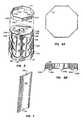
- Figure 6A is a top view of crown 240.
- Figure 6B is a side view of crown 240 illustrating the mounting tabs 242a-d and 242h.
- Figure 7 is a rear isometric view of panel 250. This embodiment permits different crowns with varying height extensions to be used on the same barrel structure. It should also be understood that the crown 240 may include more than one piece wherein the two or more crown pieces would interlock forming the crown assembly for holding the barrel assembly components in place during rotation of the barrel assembly.
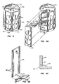
- Figure 8 illustrates a third embodiment of the present invention in assembled and exploded form in which the barrel designated 360 is comprised of a polyshaped top plate 362 on which is supported six individual susceptor panels 364a through 364f. At the underside of the barrel assembly is a corresponding polyshaped bottom plate 366 adapted to interlock with each of the individual panels 364 as will be described and is hung from the top plate via three individual vertical rods 368a, 368b and 368c.
- top plate 362 Extending through top plate 362 for receipt of the rods are bored and counterbored apertures 370a and 370b which align with slotted bores and counterbores 372a and 372b contained in bottom plate 366 for receiving and securing vertical rods 368a and 368b respectively.
- a similar aperture 370c is contained in slide 374 which when positioned in top plate 362 aligns with aperture 372c for receipt and securement of rod 368c.
- top plate 362 Centrally formed in top plate 362 is an aperture 376 through which to receive the quartz hanger 56 with temperature sensor 54 shown in Fig. 1.
- the slide includes side rails 378 on each side for slidable insert within matching top plate grooves 380. Included in the top faces of the slide is a semi circle cavity 382 that when in position in top plate 362 registers with semi circle cavity 384 in the top plate for receipt of circular disc 386. With disc 386 in position slide 374 is secured against lateral displacement outward during the course of barrel rotation.
- Each of the susceptor panels 364 includes a pair of vertically oriented wafer cavities 388a and 388b.
- the panels when collectively assembled onto top plate 362 and bottom plate 366, as will be appreciated, provide about the cavities a smooth exterior surface that is relatively obstruction free to the process gases as will be flowing in contact therewith.
- the locked mounting of the panels in position along with longitudinal interfitting joints formed between contiguous sides of adjacent panels assures the continuing integrity thereat for preventing entry of gases or light during wafer processing. This not only prevents any displacement or whatever of the panels in the course of rotation during processing but also eliminates disturbance to the surrounding gas flow as has previously been incurred.
- the adjacent panels are interfitted one to the other they secure each other against any relative bowing of the panels whereby gas flow and/or light could undesirably penetrate or gain entry to the interior of barrel 360.
- each panel 364 there is provided centrally located on the backside below the top of each panel 364 a downwardly depending hook 390 secured thereto and adapted to be inserted within an oblong recess 392 contained in top plate 362 and in slide 374. When the hooks are inserted, each panel will be secured at its topside against the edge face of the top plate facet thereat.
- each panel at its underside includes a centrally located triangular notch 404 having a complementary back draft 406 and a back edge 407. As shown in Fig. 14, leftward movement of panel 364a is positively precluded by virtue of the interlock formed between notch 404 and tab 394.
- each of the panels 364 along its backside includes a vertically extending longitudinal groove 408 parallel to side edge 410 and a vertically extending longitudinal tongue 412 formed along its side edge 414.
- Each of grooves 408 and tongues 412 extend the full panel height top to bottom.
- each of the panels when assembled to its adjacent panel forms a more or less dovetail joint 416 (see Figs. 9 and 11) nesting the adjacent panels with the side tongue 412 of the one panel interfitting the groove 408 of the adjacent panel.
- the resulting external surface at joint 416 is flush and continuous without any perceptible seam or obstruction that could disturb gas flow.
- the corners formed about joint 416 are sharp and without distortion.
- all of the panels 364 could conveniently extend above the surface of top plate 362 any desired distance "X" as shown in Fig. 10. to establish gas flow control and preheating of the gases before encountering the silicon wafers.
- FIG. 17 illustrates plug 500 which is an alternate embodiment to securing the lower ends of vertical rods 368a, 368b and 368c within counterbores 372a, 372b and 372c of bottom plate 366.
- Plug 500 is shown in FIG. 8 mounted in counterbore 372a.--
- the invention thus includes the polygon bottom panel permitting thermal expansion without damaging the base portion barrel structure, dart formations on the susceptor panel edges permitting uniform lateral gas flow, and an extended top portion for preheating the gases before they encounter the silicon wafers, and an ease of assembly onto the quartz hanger through the open facet face of the barrel which in turn easily receives the bottom plate for assembly therein. After positioning the barrel portion on the hanger, the ease of assembly of the top slide and the receptor panel are provided in a manner that prevents lateral displacement of the panel during rotation.
- the removable susceptor may be replaced by a temperature susceptor panel which is shaped as the removable susceptor panel but includes a series of temperature thermocouples that may be used to perform temperature profile studies upon the reactor in use.
- the use of this invention facilitates the accomplishment of such temperature profile studies by providing an assembly that is easily reconfigurable to include the temperature susceptor panel without excessive reactor downtime.
- each individual panel is mounted secured in a locked position to the top and bottom plates while each of the adjacent panels about the facets of the barrel are interlocked to each other to preclude formation of potential openings that could otherwise occur.
Landscapes
- Chemical & Material Sciences (AREA)
- Chemical Kinetics & Catalysis (AREA)
- General Chemical & Material Sciences (AREA)
- Engineering & Computer Science (AREA)
- Crystallography & Structural Chemistry (AREA)
- Materials Engineering (AREA)
- Metallurgy (AREA)
- Organic Chemistry (AREA)
- Chemical Vapour Deposition (AREA)
Claims (13)
- Trommelförmige Aufnahmeeinrichtung (200, 360) zum Halten von Halbleiterscheiben in mehreren Hohlräumen (210a, 210b, 210c, 388a, 388b) in Seitenwänden (208, 364a-364f) der Aufnahmeeinrichtung,
wobei die Seitenwände in einem kleinen Winkel angeordnet sind, um die Halbleiterschalen in ihren jeweiligen Hohlräumen zu halten,
wobei die Aufnahmeeinrichtung (200, 360) an einer Aufhängeeinrichtung (56)zur Drehung innerhalb eines Behälters (52) mit einer Heizeinrichtung (50) an dessen Außenseite anbringbar ist,
die Seitenwände sich im wesentlichen zwischen einer oberen Platte (201, 362) und einer unteren Platte (218, 366) der Aufnahmeeinrichtung erstrecken,
wenigstens eine dieser Seitenwände (208, 364a-364f) abnehmbar von der oberen Platte (201, 362) und der unteren Platte (218, 366) entfernbar ist,
die obere Platte (201, 362) eine Schieberöffnung, einen oberen Schieber (206, 374) zur Befestigung in der Schieberöffnung und eine Öffnung aufweist, um die Aufhängeeinrichtung (56) aufzunehmen,
und wobei die entfernbare Seitenwand, die obere Platte und die untere Platte Verriegelungseinrichtungen aufweisen,
mit denen die entfernbare Seitenwand in die obere Platte und die untere Platte eingreift,
dadurch gekennzeichnet, daß
der obere Schieber (206, 374) ferner eine Einrichtung zum Halten der entfernbaren Seitenwand (208, 364e) aufweist, die einen Hohlraum oder eine Aussparung (224, 392) enthält, die entfernbare Seitenwand (208, 364e) eine Hakeneinrichtung (230, 390) aufweist, die ergänzend zu dem Hohlraum oder Aussparung ausgebildet ist, um die entfernbare Seitenwand von dem oberen Schieber (206, 374) zu halten, und
die entfernbare Wand wenigstens eine Nut (212, 404) aufweist, die ergänzend zu einem Schwalbenschwanzverschluß (214, 394) in der unteren Platte ausgebildet ist. - Trommelförmige Aufnahmeeinrichtung nach Anspruch 1,
dadurch gekennzeichnet, daß jede einzelne Wand (208, 364a-364f) in einer verriegelten Position an der oberen Platte (201, 362) und der unteren Platte (218, 366) befestigt ist, wobei alle benachbarten Wände (208, 364a-364f) um die Seitenflächen der Trommel miteinander verriegelt sind. - Trommelförmige Aufnahmeeinrichtung nach Anspruch 1 oder 2,
dadurch gekennzeichnet, daß eine obere Verlängerung (202) oben auf der Aufnahmeeinrichtung (200) vorgesehen ist, die durch sich nach oben erstreckende Wände gebildet ist. - Trommelförmige Aufnahmeeinrichtung nach einem der Ansprüche 1 bis 3,
dadurch gekennzeichnet, daß der obere Schieber (206) ferner eine Einrichtung (222) aufweist, die verhindert, daß der Schieber von der oberen Platte (201) während der Drehung der Aufnahmeeinrichtung nach außen verlagert wird. - Trommelförmige Aufnahmeeinrichtung nach einem der Ansprüche 1 bis 4,
dadurch gekennzeichnet, daß der Schieber (374) ferner Schienen (378) aufweist, die in ergänzende Nuten (380) in der oberen Platte (362) eingreifen, um eine vertikale Abstützung zu haben. - Trommelförmige Aufnahmeeinrichtung nach einem der Ansprüche 1, 2, 4 oder 5,
dadurch gekennzeichnet, daß eine Krone (240) auf der oberen Platte (201) anbringbar ist, die sich von der oberen Platte nach oben erstreckt. - Trommelförmige Aufnahmeeinrichtung nach einem der Ansprüche 1 bis 6,
dadurch gekennzeichnet, daß die obere Platte (201) und die untere Platte (218) eine Polyederform haben und daß die Seitenwände einen polyederförmigen Abschnitt der Aufnahmeeinrichtung bilden. - Trommelförmige Aufnahmeeinrichtung nach einem der Ansprüche 1 bis 7,
dadurch gekennzeichnet, daß mehrere Seitenwände (364a-364f) vorgesehen sind, die jeweils wahlweise von der oberen Platte (362) und der unteren Platte (366) entfernbar sind, und daß Einrichtungen (368a-368c) den Abstand der unteren Platte von der oberen Platte aufrecht erhalten, wobei jede Seitenwand (364a-364f) eine Hakeneinrichtung (390) enthält, die in eine entsprechende Ausnehmung (392) in der oberen Platte (362) und des oberen Schiebers (374) eingreifen kann. - Trommelförmige Aufnahmeeinrichtung nach einem der Ansprüche 1 bis 8,
dadurch gekennzeichnet, daß Verbindungsmittel (408, 412) einzelne Wände (364a-364f) aneinander befestigen in einer gesicherten Verbindung, die im wesentlichen für Gas- und Lichteintritt aus der äußeren Prozeßumgebung undurchlässig ist. - Trommelförmige Aufnahmeeinrichtung nach Anspruch 9, dadurch gekennzeichnet, daß die Verbindungsmittel darin bestehen, daß jede Aufnahmeeinrichtungswand (364a-364f) eine vertikale Längsnut (408), die sich entlang einer Seitenkante (410) erstreckt, und eine vertikale Längszunge (412) aufweist, die sich entlang der anderen Seitenkante (414) erstreckt, wobei die Zunge der einen Wand in die Nut der angrenzenden Wand eingreift, um eine überlappende Schwalbenschwanzverbindung zwischen diesen zu bilden.
- Trommelförmige Aufnahmeeinrichtung (260) zum Halten von Halbleiterscheiben in mehreren Hohlräumen (210a, 210b, 210c) in Seitenwänden der Aufnahmeeinrichtung, wobei die Seitenwände in einem kleinen Winkel angeordnet sind, um die Halbleiterscheiben in ihren jeweiligen Hohlräumen zu halten,
die Aufnahmeeinrichtung (260) an einer Aufhängeeinrichtung (56) zur Drehung innerhalb eines Behälters (52) mit einer Heizeinrichtung (50) an dessen Außenseite anbringbar ist,
die Seitenwände sich im wesentlichen zwischen einer oberen Platte (201) und einer unteren Platte der Aufnahmeeinrichtung erstrecken,
wenigstens eine der Seitenwände (250) lösbar von der oberen Platte (201) und der unteren Platte entfernbar ist,
die obere Platte (201) eine Schieberöffnung, einen oberen Schieber (244) zur Anbringung in der Schieberöffnung und eine Öffnung hat, um die Aufhängeeinrichtung aufzunehmen, und wobei die entfernbare Seitenwand (250) und die Bodenplatte eine Verriegelungseinrichtung haben, mit der die entfernbare Seitenwand verriegelnd in die Bodenplatte eingreift,
dadurch gekennzeichnet, daß
die Aufnahmeeinrichtung (260) eine Krone (240) aufweist, die den oberen Abschnitt der entfernbaren Seitenwand (250) und den o beren Schieber (244) in Position hält,
die entfernbare Seitenwand (250) eine Wandaussparung (246c) hat, die mit einem entsprechenden Befestigungsvorsprung (242c) an der Krone (240) übereinstimmt,
die entfernbare Seitenwand (250) wenigstens eine Nut (212) aufweist, die ergänzend zu einem Schwalbenschwanzverschluß (214) in der Bodenplatte ausgebildet ist und die Krone (240) auf der oberen Platte (201) anbringbar ist, so daß sie sich von der oberen Platte nach oben erstreckt. - Trommelförmige Aufnahmeeinrichtung nach Anspruch 11,
dadurch gekennzeichnet, daß die Krone (240) mehrere Befestigungsvorsprünge (242a-h) aufweist, die mit entsprechenden Wandaussparungen (246a-h) übereinstimmen. - Trommelförmige Aufnahmeeinrichtung nach einem der Ansprüche 1 bis 12,
dadurch gekennzeichnet, daß die Seitenwände mit einer Pfeilstruktur (241) entlang aller Seitenflächenkanten der Aufnahmeeinrichtung (200, 260) versehen sind.
Applications Claiming Priority (4)
| Application Number | Priority Date | Filing Date | Title |
|---|---|---|---|
| US75753985A | 1985-07-22 | 1985-07-22 | |
| US757539 | 1985-07-22 | ||
| US06/801,978 US4823736A (en) | 1985-07-22 | 1985-11-26 | Barrel structure for semiconductor epitaxial reactor |
| US801978 | 1985-11-26 |
Publications (3)
| Publication Number | Publication Date |
|---|---|
| EP0210569A2 EP0210569A2 (de) | 1987-02-04 |
| EP0210569A3 EP0210569A3 (en) | 1987-06-16 |
| EP0210569B1 true EP0210569B1 (de) | 1991-10-30 |
Family
ID=27116401
Family Applications (1)
| Application Number | Title | Priority Date | Filing Date |
|---|---|---|---|
| EP86109997A Expired EP0210569B1 (de) | 1985-07-22 | 1986-07-21 | Trommelstruktur für Halbleiter Epitaxiereaktor |
Country Status (3)
| Country | Link |
|---|---|
| US (1) | US4823736A (de) |
| EP (1) | EP0210569B1 (de) |
| DE (1) | DE3682236D1 (de) |
Families Citing this family (35)
| Publication number | Priority date | Publication date | Assignee | Title |
|---|---|---|---|---|
| US5104276A (en) * | 1989-05-19 | 1992-04-14 | Applied Materials, Inc. | Robotically loaded epitaxial deposition apparatus |
| US5116181A (en) * | 1989-05-19 | 1992-05-26 | Applied Materials, Inc. | Robotically loaded epitaxial deposition apparatus |
| US5119540A (en) * | 1990-07-24 | 1992-06-09 | Cree Research, Inc. | Apparatus for eliminating residual nitrogen contamination in epitaxial layers of silicon carbide and resulting product |
| US5121531A (en) * | 1990-07-06 | 1992-06-16 | Applied Materials, Inc. | Refractory susceptors for epitaxial deposition apparatus |
| JPH081922B2 (ja) * | 1991-01-25 | 1996-01-10 | 株式会社東芝 | ウェハ−保持装置 |
| US5288364A (en) * | 1992-08-20 | 1994-02-22 | Motorola, Inc. | Silicon epitaxial reactor and control method |
| US5490881A (en) * | 1992-11-02 | 1996-02-13 | Gen Electric | Maintaining uniformity of deposited film thickness in plasma-enhanced chemical vapor deposition |
| DE4305750C2 (de) * | 1993-02-25 | 2002-03-21 | Unaxis Deutschland Holding | Vorrichtung zum Halten von flachen, kreisscheibenförmigen Substraten in der Vakuumkammer einer Beschichtungs- oder Ätzanlage |
| DE4305749A1 (de) * | 1993-02-25 | 1994-09-01 | Leybold Ag | Vorrichtung zum Halten von flachen, kreisscheibenförmigen Substraten in der Vakuumkammer einer Beschichtungs- oder Ätzanlage |
| US5453233A (en) * | 1993-04-05 | 1995-09-26 | Cvd, Inc. | Method of producing domes of ZNS and ZNSE via a chemical vapor deposition technique |
| US5484486A (en) * | 1994-05-02 | 1996-01-16 | Applied Materials, Inc. | Quick release process kit |
| US5988583A (en) * | 1996-10-31 | 1999-11-23 | Qualcomm Incorporated | Antenna mounting assembly |
| US5803971A (en) * | 1997-01-13 | 1998-09-08 | United Technologies Corporation | Modular coating fixture |
| US6110289A (en) * | 1997-02-25 | 2000-08-29 | Moore Epitaxial, Inc. | Rapid thermal processing barrel reactor for processing substrates |
| US5968277A (en) * | 1997-10-10 | 1999-10-19 | Seh America, Inc. | Susceptor apparatus for epitaxial deposition and method for reducing slip formation on semiconductor substrates |
| US6129048A (en) * | 1998-06-30 | 2000-10-10 | Memc Electronic Materials, Inc. | Susceptor for barrel reactor |
| IL125690A0 (en) * | 1998-08-06 | 1999-04-11 | Reiser Raphael Joshua | Furnace for processing semiconductor wafers |
| FI118474B (fi) * | 1999-12-28 | 2007-11-30 | Asm Int | Laite ohutkalvojen valmistamiseksi |
| US6811040B2 (en) * | 2001-07-16 | 2004-11-02 | Rohm And Haas Company | Wafer holding apparatus |
| ITMI20031841A1 (it) * | 2003-09-25 | 2005-03-26 | Lpe Spa | Suscettore per reattori epitassiali ad induzione. |
| US7462246B2 (en) * | 2005-04-15 | 2008-12-09 | Memc Electronic Materials, Inc. | Modified susceptor for barrel reactor |
| US20080314319A1 (en) * | 2007-06-19 | 2008-12-25 | Memc Electronic Materials, Inc. | Susceptor for improving throughput and reducing wafer damage |
| US8353259B2 (en) * | 2007-08-24 | 2013-01-15 | United Technologies Corporation | Masking fixture for a coating process |
| US8404049B2 (en) * | 2007-12-27 | 2013-03-26 | Memc Electronic Materials, Inc. | Epitaxial barrel susceptor having improved thickness uniformity |
| US20100098519A1 (en) * | 2008-10-17 | 2010-04-22 | Memc Electronic Materials, Inc. | Support for a semiconductor wafer in a high temperature environment |
| TW201122148A (en) * | 2009-12-24 | 2011-07-01 | Hon Hai Prec Ind Co Ltd | Chemical vapor deposition device |
| US9441295B2 (en) * | 2010-05-14 | 2016-09-13 | Solarcity Corporation | Multi-channel gas-delivery system |
| US8986451B2 (en) * | 2010-05-25 | 2015-03-24 | Singulus Mocvd Gmbh I. Gr. | Linear batch chemical vapor deposition system |
| US9869021B2 (en) | 2010-05-25 | 2018-01-16 | Aventa Technologies, Inc. | Showerhead apparatus for a linear batch chemical vapor deposition system |
| US9169562B2 (en) | 2010-05-25 | 2015-10-27 | Singulus Mocvd Gmbh I. Gr. | Parallel batch chemical vapor deposition system |
| KR20120083712A (ko) * | 2011-01-18 | 2012-07-26 | 삼성엘이디 주식회사 | 서셉터 및 이를 구비하는 화학 기상 증착 장치 |
| US20160359080A1 (en) | 2015-06-07 | 2016-12-08 | Solarcity Corporation | System, method and apparatus for chemical vapor deposition |
| US9748434B1 (en) | 2016-05-24 | 2017-08-29 | Tesla, Inc. | Systems, method and apparatus for curing conductive paste |
| US9954136B2 (en) | 2016-08-03 | 2018-04-24 | Tesla, Inc. | Cassette optimized for an inline annealing system |
| US10115856B2 (en) | 2016-10-31 | 2018-10-30 | Tesla, Inc. | System and method for curing conductive paste using induction heating |
Family Cites Families (5)
| Publication number | Priority date | Publication date | Assignee | Title |
|---|---|---|---|---|
| US3749383A (en) * | 1971-04-29 | 1973-07-31 | Rca Corp | Apparatus for processing semiconductor devices |
| US3796182A (en) * | 1971-12-16 | 1974-03-12 | Applied Materials Tech | Susceptor structure for chemical vapor deposition reactor |
| US4099041A (en) * | 1977-04-11 | 1978-07-04 | Rca Corporation | Susceptor for heating semiconductor substrates |
| US4496828A (en) * | 1983-07-08 | 1985-01-29 | Ultra Carbon Corporation | Susceptor assembly |
| US4612207A (en) * | 1985-01-14 | 1986-09-16 | Xerox Corporation | Apparatus and process for the fabrication of large area thin film multilayers |
-
1985
- 1985-11-26 US US06/801,978 patent/US4823736A/en not_active Expired - Fee Related
-
1986
- 1986-07-21 EP EP86109997A patent/EP0210569B1/de not_active Expired
- 1986-07-21 DE DE8686109997T patent/DE3682236D1/de not_active Expired - Fee Related
Also Published As
| Publication number | Publication date |
|---|---|
| US4823736A (en) | 1989-04-25 |
| EP0210569A3 (en) | 1987-06-16 |
| DE3682236D1 (de) | 1991-12-05 |
| EP0210569A2 (de) | 1987-02-04 |
Similar Documents
| Publication | Publication Date | Title |
|---|---|---|
| US4823736A (en) | Barrel structure for semiconductor epitaxial reactor | |
| EP0131208B1 (de) | Suszeptor-Anordnung | |
| EP0746009B1 (de) | Mehrschichtige Susceptor für schnelle thermische Behandlungsreaktoren | |
| CA1302110C (en) | Tile assembly | |
| US4593826A (en) | Display rack with improved shelf mounts | |
| US5507873A (en) | Vertical boat | |
| EP0211692B1 (de) | Vorrichtung zum Festhalten von elektrischen oder elektronischen Bauteilen während der Anwendung von Lötmitteln | |
| US5033406A (en) | Side lifting tool wafer-boat assembly | |
| KR920001025B1 (ko) | 반도체 웨이퍼 지지용 조립장치 | |
| JPS62202870A (ja) | セラミツクスハニカム構造体の焼成方法 | |
| US4516897A (en) | Cantilever paddle for use with wafer boats | |
| US5299555A (en) | Frame element for forming a grate | |
| EP0531398B1 (de) | Tragevorrichtung für waren | |
| JPS6258617A (ja) | 半導体エピタキシヤル反応器のバレル構造 | |
| US4079563A (en) | Ceiling runner locking means | |
| JPS6155766B2 (de) | ||
| US5222890A (en) | Device for the sagger-less burning of crockery | |
| JPS59143586A (ja) | 多穴容器 | |
| JPS6220159B2 (de) | ||
| JP3130067B2 (ja) | 半導体ウエハ用バスケット | |
| JPH05229581A (ja) | ウエハキャリアケース | |
| JPH08165742A (ja) | 天井格子パネル | |
| EP0225111A2 (de) | Herstellen von Trägerhorde für Scheiben und Produkt | |
| JPH0121968Y2 (de) | ||
| JPH0824140B2 (ja) | シリコンウエ−ハ処理用治具 |
Legal Events
| Date | Code | Title | Description |
|---|---|---|---|
| PUAI | Public reference made under article 153(3) epc to a published international application that has entered the european phase |
Free format text: ORIGINAL CODE: 0009012 |
|
| AK | Designated contracting states |
Kind code of ref document: A2 Designated state(s): DE FR IT NL |
|
| PUAL | Search report despatched |
Free format text: ORIGINAL CODE: 0009013 |
|
| AK | Designated contracting states |
Kind code of ref document: A3 Designated state(s): DE FR IT NL |
|
| 17P | Request for examination filed |
Effective date: 19870827 |
|
| 17Q | First examination report despatched |
Effective date: 19890202 |
|
| RAP1 | Party data changed (applicant data changed or rights of an application transferred) |
Owner name: MTC ACQUISITION CORPORATION THE CARBON/GRAPHITE GR |
|
| GRAA | (expected) grant |
Free format text: ORIGINAL CODE: 0009210 |
|
| AK | Designated contracting states |
Kind code of ref document: B1 Designated state(s): DE FR IT NL |
|
| ITF | It: translation for a ep patent filed | ||
| REF | Corresponds to: |
Ref document number: 3682236 Country of ref document: DE Date of ref document: 19911205 |
|
| ET | Fr: translation filed | ||
| PLBE | No opposition filed within time limit |
Free format text: ORIGINAL CODE: 0009261 |
|
| STAA | Information on the status of an ep patent application or granted ep patent |
Free format text: STATUS: NO OPPOSITION FILED WITHIN TIME LIMIT |
|
| 26N | No opposition filed | ||
| PGFP | Annual fee paid to national office [announced via postgrant information from national office to epo] |
Ref country code: FR Payment date: 19960716 Year of fee payment: 11 |
|
| PG25 | Lapsed in a contracting state [announced via postgrant information from national office to epo] |
Ref country code: FR Free format text: LAPSE BECAUSE OF NON-PAYMENT OF DUE FEES Effective date: 19980331 |
|
| NLV4 | Nl: lapsed or anulled due to non-payment of the annual fee |
Effective date: 19980201 |
|
| REG | Reference to a national code |
Ref country code: FR Ref legal event code: ST |
|
| NLXE | Nl: other communications concerning ep-patents (part 3 heading xe) |
Free format text: A REQUEST FOR RESTORATION TO THE PRIOR STATE HAS BEEN FILED ON 17.07.98 |
|
| NLXE | Nl: other communications concerning ep-patents (part 3 heading xe) |
Free format text: THE REQUEST FOR RESTORATION TO THE PRIOR STATE AS PROVIDED FOR IN ART. 17A OF THE PATENTS ACT (SEE PUBLICATION IN HEADING XE OF THE PATENT BULLETIN OF 01.09.98/09) HAS BEEN GRANTED; THE RESTORATION HAS BEEN ENTERED IN THE PATENT REGISTER. |
|
| PGFP | Annual fee paid to national office [announced via postgrant information from national office to epo] |
Ref country code: DE Payment date: 20010831 Year of fee payment: 16 |
|
| PGFP | Annual fee paid to national office [announced via postgrant information from national office to epo] |
Ref country code: NL Payment date: 20020731 Year of fee payment: 17 |
|
| PG25 | Lapsed in a contracting state [announced via postgrant information from national office to epo] |
Ref country code: DE Free format text: LAPSE BECAUSE OF NON-PAYMENT OF DUE FEES Effective date: 20030201 |
|
| PG25 | Lapsed in a contracting state [announced via postgrant information from national office to epo] |
Ref country code: NL Free format text: LAPSE BECAUSE OF NON-PAYMENT OF DUE FEES Effective date: 20040201 |
|
| NLV4 | Nl: lapsed or anulled due to non-payment of the annual fee |
Effective date: 20040201 |
|
| PG25 | Lapsed in a contracting state [announced via postgrant information from national office to epo] |
Ref country code: IT Free format text: LAPSE BECAUSE OF NON-PAYMENT OF DUE FEES;WARNING: LAPSES OF ITALIAN PATENTS WITH EFFECTIVE DATE BEFORE 2007 MAY HAVE OCCURRED AT ANY TIME BEFORE 2007. THE CORRECT EFFECTIVE DATE MAY BE DIFFERENT FROM THE ONE RECORDED. Effective date: 20050721 |