EP0210392A2 - Process for separating nitrogen oxides from gases, in particular from fumes - Google Patents
Process for separating nitrogen oxides from gases, in particular from fumes Download PDFInfo
- Publication number
- EP0210392A2 EP0210392A2 EP86107974A EP86107974A EP0210392A2 EP 0210392 A2 EP0210392 A2 EP 0210392A2 EP 86107974 A EP86107974 A EP 86107974A EP 86107974 A EP86107974 A EP 86107974A EP 0210392 A2 EP0210392 A2 EP 0210392A2
- Authority
- EP
- European Patent Office
- Prior art keywords
- adsorbent
- reducing agent
- reactor
- gas
- loading
- Prior art date
- Legal status (The legal status is an assumption and is not a legal conclusion. Google has not performed a legal analysis and makes no representation as to the accuracy of the status listed.)
- Withdrawn
Links
Images
Classifications
-
- B—PERFORMING OPERATIONS; TRANSPORTING
- B01—PHYSICAL OR CHEMICAL PROCESSES OR APPARATUS IN GENERAL
- B01D—SEPARATION
- B01D53/00—Separation of gases or vapours; Recovering vapours of volatile solvents from gases; Chemical or biological purification of waste gases, e.g. engine exhaust gases, smoke, fumes, flue gases, aerosols
- B01D53/34—Chemical or biological purification of waste gases
- B01D53/74—General processes for purification of waste gases; Apparatus or devices specially adapted therefor
- B01D53/86—Catalytic processes
- B01D53/8621—Removing nitrogen compounds
- B01D53/8625—Nitrogen oxides
-
- B—PERFORMING OPERATIONS; TRANSPORTING
- B01—PHYSICAL OR CHEMICAL PROCESSES OR APPARATUS IN GENERAL
- B01D—SEPARATION
- B01D2251/00—Reactants
- B01D2251/20—Reductants
- B01D2251/206—Ammonium compounds
- B01D2251/2062—Ammonia
-
- B—PERFORMING OPERATIONS; TRANSPORTING
- B01—PHYSICAL OR CHEMICAL PROCESSES OR APPARATUS IN GENERAL
- B01D—SEPARATION
- B01D2253/00—Adsorbents used in seperation treatment of gases and vapours
- B01D2253/10—Inorganic adsorbents
- B01D2253/102—Carbon
Definitions
- the invention relates to a method for separating NO from exhaust gases, in particular flue gases, of the type mentioned in the preamble of claim 1 above.
- Flue gases are understood to mean those flue gases which are produced during the combustion of low-sulfur fuels or whose sulfur dioxide proportions are reduced by an upstream desulfurization system based on, for example, a wet, semi-dry, dry process. Solutions or suspensions based on Ca, Mg, Na, NH 3 , for example, are used as absorbents for removing the sulfur dioxide components, as described, for example, in W. Kaminsky, Chem. Ing.-Technik 55 (1983), page 673 ff. In addition to a substantial reduction in sulfur oxides, a reduction in the nitrogen oxide content in the flue gases is required today.
- a method of the type mentioned in the preamble of claim 1 above is known, for example, from DE-OS 29 11 712, in which the nitrogen oxides are catalytically reduced to nitrogen to produce steam in a moving layer of carbon-containing adsorbents after metered addition of gaseous ammonia as reducing agent .
- This method has the disadvantage that the addition of the reducing agent into the flue gas alone before it enters the adsorbent bed achieves a sufficiently high degree of separation of greater than 60% only if the treated exhaust gas has a very high level R edutechnischsmittelschreibtechnikschuß based having on the nitrogen oxide content of the exhaust stream to be deposited.
- the invention is based on the knowledge that the reaction between the nitrogen oxides and the reducing agent takes place on the outer and inner surface of the adsorbent.
- the precharging according to the invention ensures that reducing agent is constantly stored on the outer and inner reaction surface of the solid adsorbent and is available for reaction with the nitrogen oxides contained in the exhaust gas.
- the reducing agent In comparison to a supply of the reducing agent into the gas stream before it is brought into contact with the adsorbent, the reducing agent does not have to reach the inner reaction surface of the adsorbent from the gas phase by film and / or pore diffusion, so that the pre-loading leads to a corresponding one, when the adsorbent is preloaded Leads to an increase in the reaction rate; consequently, each nitrogen oxide molecule that diffuses through the pores to the inner surface is immediately opposed to a molecule of the reducing agent as a reduction partner.
- the pre-loading is preferably carried out according to the features of claim 2. A guidance of the two material flows in countercurrent is preferred.
- the adsorbent can be transported in the direction of gravity (moving bed) or, for example, by fluidization via the reducing agent (e.g. swirl channel) or by mechanical installations within the pre-loading stage, which transfer the movement to the adsorbent bed.
- the reducing agent e.g. swirl channel
- the preloaded adsorbent is fed to a moving bed reactor.
- the preloaded adsorbent from the preloading stage is preferably fed in at its upper end and removed at its lower end, suitable feed and extraction locks being provided in each case.
- Abrasion and any solid reaction products formed between the reducing agent and the remaining sulfur oxides when desulfurization is added are removed from the adsorbent after exiting the reactor (e.g. sieving, sifting) in order to avoid loss of activity due to clogging of the pores of the solid adsorbent.
- the temperature range mentioned above, in which the preloaded adsorbent is brought into contact with the gas stream to be de-stiked, can be achieved by re-heating the preferably desulfurized exhaust gas by means of a heat exchanger (regenerative with flue gas or with external energy).
- the preloaded adsorbent can also be fed into a fixed bed reactor from a moving bed reactor. In these two cases, it is possible to abandon the entstickende flue gas and the reducing agent Adsorptionsmittelreaktoren two alternately with flue gas flows through b zw. Are loaded with the reducing agent, as claimed in claim 6.
- the reducing agent is used in a mixture with a diluent gas for pre-loading.
- excess reducing agent is added to the exhaust gas stream prior to its contact with the pre-loaded adsorbent, i.e. the remaining proportions of reducing agent, which are not absorbed by the adsorbent in the pre-loading stage, can be mixed into the exhaust gas from the gas phase of the pre-loading stage before entering the denitrification reactor. If the denitrification takes place in moving bed reactors, it is expedient to add fresh adsorbent to the adsorbent for pre-loading to compensate for the abrasion.
- the optimal rate of migration of the adsorbent through the adsorbent reactor is essentially determined by the denitrification parameters (primarily the degree of separation of the nitrogen oxides) and the change in pressure loss in the moving bed.
- the preloading of the adsorbent on the solids residence time of the adsorbent with the reducing agent, the concentration of the educts R tion by means of the charging gas and / or the temperature is in the pre-loading level.
- the nitrogen oxides to be separated are separated according to claim 11, but the aim is that a substantial proportion of the reducing agent is fed to the catalytic reaction via the pre-loading. It is therefore again preferred that 20% to 100% of the pre-charge be fed and only 80% to 0% be introduced into the exhaust gas before the catalytic reaction, preferably 50% to 100% or 50% to 0%.
- the reaction rate can be increased and the excess ammonia content can be reduced, as the following example shows, in which the excess ammonia content in purified gas is 6.0 mg / m 3 n compared to the excess of reducing agent in the known process in the amount of approximately 30 mg / m 3 n .
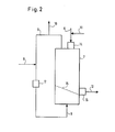
- FIG. 2 shows a preferred embodiment for the pre-loading stage 7.
- the preloading of the adsorbent supplied via line 6 with reducing agent was carried out in the example shown in a moving layer reactor 7, in the upper part of which the adsorbent is fed from the NO x separating stage 5 via a gas-tight lock 14 and during the migration through the reactor 7 with the Reducing agent 8 is loaded in countercurrent.
- a gas-permeable inclined distributor base 15 pre-loaded adsorbent is drawn off via a gas-tight lock 16 and fed to the adsorbent reactor 5 via line 12, for example pneumatically or mechanically via a bucket elevator.
- Fresh adsorbent is added via line 11, which replaces the abrasion in the NO separation stage 5.
- the x reducing agent is fed via a blower 17 and the line 8 to the cavity under the gas-permeable distributor floor 3, which ensures a uniform distribution of the reducing agent over the adsorbent migrating bed 7.
- a small proportion of reducing agent is drawn off via line 9.
- a partial stream of the excess of reducing agent withdrawn in this way can be mixed in via line 10 into the gas phase upstream of the adsorbent reactor 5.
- the required reducing agent for the respective NO separation is introduced in the manner shown via line 8, into which the blower 17 is switched on. Whereby - as already mentioned - the loading circuit can be circulated via lines 8 and 9.
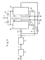
- two adsorbent reactors 5a and 5b are provided, which can be operated as fixed bed or moving bed reactors. These are acted upon by the flue gas in countercurrent or cocurrent, preferably crossflow.
- the reducing agent or reducing agent / diluent gas mixture is passed through the feed line 8 through the reactor 5a with the valves 17 and 18 or the valves 19 and 20 open.
- the proportions of the reducing agent which are not absorbed by the adsorbent can be circulated via line 9a or can be mixed into the flue gas via line 10a, 10.
- the flue gas is passed through the reactor 5a with the shutoff element 4a 'open or the shutoff element 4b' closed and leaves it cleaned of nitrogen oxides via line 13 &.
- reactor 5b With open valves 19 and 20 and closed valves 17 and 18, reactor 5b is supplied with reducing agent in a circulating manner via line 9b while valves 5 and 20 are open.
- Reactor 5a is now the operation described in connection with the reactor 5b with R educts analogously applied tion medium.
- the reactors 5a and 5b are thus used alternately for nitrogen oxide separation.
- the preloading of the adsorbent with the Reducing agents have to be carried out in such a way that the loading height to be achieved is reached within the time that the other reactor can be supplied with flue gas.
- the degree of loading of the adsorbent can be set, for example, via the volume flow of the reducing agent or its concentration in the reducing agent mixture.
- the flue gas from a dry-ashed coal-fired system shows the following data behind a lime-based flue gas desulfurization system and the reheating:
- the moving bed reactor is carried out in two stages in this example, so that in the first stage the SO z residues contained behind the flue gas desulfurization system are separated off on carbon-containing adsorbents by the known method.
- the adsorbent loaded with sulfuric acid is thermally regenerated according to the known method and added again at the top of the reactor.
- the flue gas cleaned in this way contains 195 mg / m 3 n of nitrogen oxides, calculated as N0 2 , after exiting the adsorbent reactor in both cases a) and b).
- the excess ammonia content in the cleaned exhaust gas is 6.0 mg / m and in case b) 10 mg / m 3 n .
Abstract
Bei unserem Verfahren zur Abscheidung von NOx aus Gasen, insbesondere Rauchgasen, bei dem das NOx aus dem Rauchgas an einem festen Adsorptionsmittel, insbesondere Aktivkohle/Aktivkoks. unter Zugabe eines Reduktionsmittels, insbesondere Ammoniak. CO, Wasserstoff, katalytisch abgetrennt wird und bei dem das Adsorptionsmittel mehrmals hintereinander mit dem zu entstickenden Gas in Kontakt gebracht wird. ist zur weiteren NOx-Minderung vorgesehen, daß das Adsorptionsmittel mit zumindest einem Anteil an Reduktionsmittel vorbeladen und danach mit dem zu entstickenden Gasstrom in Berührung gebracht wird.In our process for the separation of NOx from gases, especially flue gases, in which the NOx from the flue gas on a solid adsorbent, especially activated carbon / activated coke. with the addition of a reducing agent, especially ammonia. CO, hydrogen, is separated catalytically and in which the adsorbent is brought into contact with the gas to be denitrified several times in succession. For further NOx reduction, it is provided that the adsorbent is preloaded with at least a proportion of reducing agent and then brought into contact with the gas stream to be denitrified.
Description
Die Erfindung betrifft ein Verfahren zur Abscheidung von NO aus Abgasen, insbesondere Rauchgasen, der im Oberbegriff des vorstehenden Anspruches 1 genannten Art.The invention relates to a method for separating NO from exhaust gases, in particular flue gases, of the type mentioned in the preamble of claim 1 above.
Unter Rauchgasen werden solche Rauchgase verstanden, die bei der Verbrennung schwefelarmer Brennstoffe entstehen bzw. deren Schwefeldioxidanteile durch eine vorgeschaltete Entschwefelungsanlage basierend auf einem z.B. nassen, halbtrockenen, trockenen Verfahren vermindert werden. Als Absorptionsmittel zur Entfernung der Schwefeldioxidanteile kommen dabei z.B. Lösungen bzw. Suspensionen auf Ca-, Mg-, Na-, NH3-Basis zum Einsatz, wie dies z.B. in W. Kaminsky, Chem. Ing.-Technik 55 (1983), Seite 673 ff beschrieben ist. Neben einer weitgehenden Reduzierung der Schwefeloxide wird aber heute eine Minderung des Stickoxidgehaltes in den Rauchgasen gefordert. Ein Verfahren der im Oberbegriff des vorstehenden Anspruches 1 genannten Art ist z.B. aus der DE-OS 29 11 712 bekannt, bei dem in einer Wanderschicht aus kohlenstoffhaltigen Adsorptionsmitteln nach dosierter Zugabe von gasförmigen Ammoniak als Reduktionsmittel die Stickstoffoxide katalytisch zu Stickstoff unter Erzeugung von Wasserdampf reduziert werden. Dies Verfahren hat den Nachteil, daß durch die alleinige Zugabe des Reduktionsmittels in das Rauchgas vor dem Eintritt desselben in das Adsorptionsmittelbett ein ausreichend hoher Abscheidegrad von größer als 60 % nur dann erreicht wird, wenn das behandelte Abgas einen sehr hohen Reduktionsmittelüberschuß bezogen auf den abzuscheidenden Stickstoffoxidgehalt des Abgasstroms aufweist.Flue gases are understood to mean those flue gases which are produced during the combustion of low-sulfur fuels or whose sulfur dioxide proportions are reduced by an upstream desulfurization system based on, for example, a wet, semi-dry, dry process. Solutions or suspensions based on Ca, Mg, Na, NH 3 , for example, are used as absorbents for removing the sulfur dioxide components, as described, for example, in W. Kaminsky, Chem. Ing.-Technik 55 (1983), page 673 ff. In addition to a substantial reduction in sulfur oxides, a reduction in the nitrogen oxide content in the flue gases is required today. A method of the type mentioned in the preamble of claim 1 above is known, for example, from DE-OS 29 11 712, in which the nitrogen oxides are catalytically reduced to nitrogen to produce steam in a moving layer of carbon-containing adsorbents after metered addition of gaseous ammonia as reducing agent . This method has the disadvantage that the addition of the reducing agent into the flue gas alone before it enters the adsorbent bed achieves a sufficiently high degree of separation of greater than 60% only if the treated exhaust gas has a very high level R eduktionsmittelüberschuß based having on the nitrogen oxide content of the exhaust stream to be deposited.
Es ist daher die Aufgabe der vorliegenden Erfindung, ein Verfahren der im Oberbegriff des vorstehenden Anspruches 1 genannten Art anzugeben, bei dem ein hoher Abscheidungsgrad ohne unzulässig hohen Reduktionsmittelüberschuß erreicht wird.It is therefore the object of the present invention to provide a method of the type mentioned in the preamble of claim 1 above, in which a high degree of separation is achieved without an excessively high excess of reducing agent.
Diese Aufgabe wird erfindungsgemäß durch die Merkmale im Kennzeichen des Anspruches 1 gelöst.This object is achieved by the features in the characterizing part of claim 1.
Die Erfindung geht dabei von der Erkenntnis aus, daß die Reaktion zwischen den Stickoxiden und dem Reduktionsmittel an der äußeren und inneren Oberfläche des Adsorptionsmittels abläuft. Durch die erfindungsgemäße Vorbeladung wird erreicht, daß an der äußeren und inneren Reaktionsoberfläche des Feststoffadsorptionsmittels ständig Reduktionsmittel gespeichert wird und für die Reaktion mit den im Abgas enthaltenen Stickoxiden zur Verfügung steht. Im Vergleich zu einer Zufuhr des Reduktionsmittels in den Gasstrom vor dessen Inkontaktbringen mit dem Adsorptionsmittel muß das Reduktionsmittel bei Vorbeladung des Adsorptionsmittels nicht erst aus der Gasphase durch Film-und/oder Porendiffusion an die innere Reaktionsoberfläche des Adsorptionsmittels gelangen, so daß die Vorbeladung zu einer entsprechenden Erhöhung der Reaktionsgeschwindigkeit führt; mithin steht jedem Stickstoffoxid-Molekül, das durch die Poren zur inneren Oberfläche diffundiert, sofort ein Molekül des Reduktionsmittels als Reduktionspartner gegenüber. Vorzugsweise erfolgt die Vorbeladung gemäß den Merkmalen des Anspruches 2. Dabei wird eine Führung der beiden Stoffströme im Gegenstrom bevorzugt. Der Transport des Adsorptionsmittels kann dabei in Richtung der Schwerkraft erfolgen (Wanderbett) oder z.B. auch durch Fluidisierung über das Reduktionsmittel (z.B. Wirbelrinne) oder durch mechanische Einbauten innerhalb der Vorbeladungsstufe, die die Bewegung auf die Adsorptionsmittelschüttung übertragen. Wie bereits erwähnt ist es von Vorteil, das erfindungsgemäße Verfahren einer Rauchgasentschwefelung nachzuschalten. Es ist daher vorgesehen, daß das beladene Adsorptionsmittel in einen vorentschwefelten Rauchgasstrom eingebracht wird, der nach der Entschwefelung auf eine Temperatur von 60 °C - 180 °C vorzugsweise 80 °C - 180 °C erwärmt wird.The invention is based on the knowledge that the reaction between the nitrogen oxides and the reducing agent takes place on the outer and inner surface of the adsorbent. The precharging according to the invention ensures that reducing agent is constantly stored on the outer and inner reaction surface of the solid adsorbent and is available for reaction with the nitrogen oxides contained in the exhaust gas. In comparison to a supply of the reducing agent into the gas stream before it is brought into contact with the adsorbent, the reducing agent does not have to reach the inner reaction surface of the adsorbent from the gas phase by film and / or pore diffusion, so that the pre-loading leads to a corresponding one, when the adsorbent is preloaded Leads to an increase in the reaction rate; consequently, each nitrogen oxide molecule that diffuses through the pores to the inner surface is immediately opposed to a molecule of the reducing agent as a reduction partner. The pre-loading is preferably carried out according to the features of claim 2. A guidance of the two material flows in countercurrent is preferred. The adsorbent can be transported in the direction of gravity (moving bed) or, for example, by fluidization via the reducing agent (e.g. swirl channel) or by mechanical installations within the pre-loading stage, which transfer the movement to the adsorbent bed. As already mentioned, it is advantageous to use flue gas desulfurization after the process according to the invention. It is therefore provided that the loaded adsorbent is introduced into a pre-desulfurized flue gas stream which, after desulfurization, is heated to a temperature of 60 ° C - 180 ° C, preferably 80 ° C - 180 ° C.
Eine einfache Verfahrensführung wird erreicht, wenn das vorbeladene Adsorptionsmittel einem Wanderbettreaktor zugeführt wird. Dabei wird vorzugsweise an dessen oberem Ende das vorbeladene Adsorptionsmittel aus der Vorbeladungsstufe aufgegeben und an dessen unterem Ende abgenommen, wobei jeweils geeignete Zufuhr- bzw. Abzugsschleusen vorgesehen sind. Abrieb und bei Vorschaltung einer Entschwefelung evtl. gebildete feste Reaktionsprodukte zwischen dem Reduktionsmittel und den restlichen Schwefeloxiden werden nach dem Austritt aus dem Reaktor vom Adsorptionsmittel entfernt (z.B. Absieben, Sichten) um einen Aktivitätsverlust durch Verstopfung der Poren des Feststoffadsorptionsmittels zu vermeiden.A simple procedure is achieved if the preloaded adsorbent is fed to a moving bed reactor. In this case, the preloaded adsorbent from the preloading stage is preferably fed in at its upper end and removed at its lower end, suitable feed and extraction locks being provided in each case. Abrasion and any solid reaction products formed between the reducing agent and the remaining sulfur oxides when desulfurization is added are removed from the adsorbent after exiting the reactor (e.g. sieving, sifting) in order to avoid loss of activity due to clogging of the pores of the solid adsorbent.
Vorstehend erwähnter Temperaturbereich, bei dem das vorbeladene Adsorptionsmittel in Berührung mit dem zu entstikkenden Gasstrom gebracht wird, kann durch Wiederaufheizung des vorzugsweise entschwefelten Abgases mittels Wärmetauscher (regenerativ mit Rohrauchgasen oder mit Fremdenergie) erfolgen. Aus einem Wanderbettreaktor kann das vorbeladene Adsorptionsmittel auch einem Festbettreaktor aufgegeben werden. In diesen beiden Fällen ist es möglich, das zu entstickende Rauchgas und das Reduktionsmittel zwei Adsorptionsmittelreaktoren aufzugeben, die abwechselnd mit Rauchgas durchströmt bzw. mit dem Reduktionsmittel beladen werden, wie dies im Anspruch 6 beansprucht ist. Beim Umschalten des mit Reduktionsmittel vorbeladenen Reaktors auf Abgas- bzw. Rauchgasbetrieb erfolgt eine Reaktion des adsorptiv gebundenen Reduktionsmittels mit den Stickstoffoxiden des Abgases. Reaktionsprodukte von Schwefeloxiden mit dem Reduktionsmittel werden durch Austrag einer Teilmenge des Adsorptionsmittels entfernt und das Adsorptionsmittel wird nach der Regeneration in einen der Behälter zurückgeführt. Die Regeneration von Feststoffadsorptionsmitteln ist an sich bekannt.The temperature range mentioned above, in which the preloaded adsorbent is brought into contact with the gas stream to be de-stiked, can be achieved by re-heating the preferably desulfurized exhaust gas by means of a heat exchanger (regenerative with flue gas or with external energy). The preloaded adsorbent can also be fed into a fixed bed reactor from a moving bed reactor. In these two cases, it is possible to abandon the entstickende flue gas and the reducing agent Adsorptionsmittelreaktoren two alternately with flue gas flows through b zw. Are loaded with the reducing agent, as claimed in
In vielen Fällen reicht es aus, daß zur Vorbeladung das Reduktionsmittel in Mischung mit einem Verdünnungsgas verwendet wird.In many cases it is sufficient that the reducing agent is used in a mixture with a diluent gas for pre-loading.
Gemäß Anspruch 8 wird bei der Vorbeladung überschüssiges Reduktionsmittel dem Abgasstrom vor dessen Kontakt mit dem vorbeladenen Adsorptionsmittel zugesetzt, d.h. die Restanteile an Reduktionsmittel, die in der Vorbeladungsstufe nicht vom Adsorptionsmittel aufgenommen werden, können aus der Gasphase der Vorbeladungsstufe in das Abgas vor Eintritt in- den Entstickungsreaktor eingemischt werden. Falls die Entstickung in Wanderbettreaktoren erfolgt, ist es zweckmäßig, frisches Adsorptionsmittel zum Ausgleich des Abriebs dem Adsorptionsmittel bei Vorbeladung zuzusetzen. Im Zusammenhang mit der Reinigung in Wanderbettreaktoren soll noch darauf hingewiesen werdnen, daß die optimale Wanderungsgeschwindigkeit des Adsorptionsmittels durch den Adsorptionsmittelreaktor im wesentlichen von den Entstickungsparatametern (vornehmlich dem Abscheidegrad der Stickoxide) und der Druckverluständerung im Wanderbett bestimmt wird.According to
Gemäß Anspruch 10 wird die Vorbeladung des Adsorptionsmittels über die Feststoffverweilzeit des Adsorptionsmittels mit dem Reduktionsmittel, die Konzentration des Reduk- tionsmittels im Beladungsgas und/oder die Temperatur in der Vorbeladungsstufe eingestellt.According to
Es kann zweckmäßig sein, daß entsprechend dem abzuscheidenden Stoffstrom an Stickoxiden gemäß Anspruch 11 verfahren wird, dabei wird jedoch angestrebt, daß ein wesentlicher Anteil des Reduktionsmittels über die Vorbeladung der katalytischen Reaktion zugeführt wird. Es wird daher wiederum bevorzugt, daß 20 % - 100 % der Vorbeladung zugeführt werden und nur 80 % - 0 % in das Abgas vor katalytische Reaktion eingeleitet werden, vorzugsweise 50 % - 100 % bzw. 50 % - 0 %.It may be expedient that the nitrogen oxides to be separated are separated according to claim 11, but the aim is that a substantial proportion of the reducing agent is fed to the catalytic reaction via the pre-loading. It is therefore again preferred that 20% to 100% of the pre-charge be fed and only 80% to 0% be introduced into the exhaust gas before the catalytic reaction, preferably 50% to 100% or 50% to 0%.
Zusammenfassend kann gesagt werden, daß durch die Vorbeladung des Adsorptionsmittels mit Reduktionsmittel die Reaktionsgeschwindigkeit erhöht und der Gehalt an überschüssigem Ammoniak erniedrigt werden kann, wie das nachfolgende Beispiel zeigt, bei dem der Gehalt an überschüssigem Ammoniak in gereinigtem Gas 6,0 mg/m3 n gegenüber dem Reduktionsmittelüberschuß bei der bekannten Verfahrensführung in Höhe von ca. 30 mg/m3 n.In summary, it can be said that by preloading the adsorbent with reducing agent, the reaction rate can be increased and the excess ammonia content can be reduced, as the following example shows, in which the excess ammonia content in purified gas is 6.0 mg / m 3 n compared to the excess of reducing agent in the known process in the amount of approximately 30 mg / m 3 n .
Die Erfindung soll nun anhand der beigefügten Figuren und in einem Beispiel näher beschrieben werden. Es zeigt:
- Figur 1 eine Darstellung des Verfahrensschemas für NOx-Abscheidung in einem Wanderschichtreaktcr bei vorheriger S02-Abscheidung,
- Figur 2 eine schematische Darstellung der Vorbeladungsstufe zur Vorbaladung des Adsorptionsmittels mit Reduktionsmittel, wie sie bei der Ausführungsform gemäß Figur 1 zum Einsatz kommen kann und
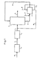
- Figur 3 eine schematische Darstellung der Verfahrensführung, bei der zwei Reaktoren jeweils abwechselnd mit dem Reduktionsmittel beladen und anschließend vom zu entstikkenden Abgas durchstromt werden. Gemäß Figur 1 wird Rauchgas RG einer Entschwefelungsanlage 1, die auf einem trockenen, halbtrockenen oder nassen Entschwefelungsverfahren basiert, entschwefelt. Beispiele für Entschwefelungsverfahren sind in der Beschreibungseinleitung angegeben. Das entschwefelte Gas wird über eine Rohrleitung 2 einem Wärmetauscher 3 zugeführt, um es auf die Eintrittstemperatur des Reaktors im Bereich von 60 °C - 180 °C zu erwärmen. Die Notwendigkeit einer Erwärmung und die Erwärmungstemperaturdifferenz hängt von dem vorgeschalteten Entschwefelungsverfahren ab. Über eine Leitung 4 wird das erwärmte und entschwefelte Rauchgas einem Adsorptionsmittelreaktor zugeführt, der vorzugsweise mit einem kohlestoffhaltigen Feststoff-Adsorptionsmittel gefüllt ist. Gemäß Figur 1 ist der Adsorpionsmittelreaktor ein Wanderbettreaktor, wobei abgezogenes Adsorptionsmittel nach bekannten Verfahren von Abrieb und evtl. Reaktionsprodukten der Rauchgasentschwefelung gereinigt wird. Über eine
Leitung 6 wird das Adsorptionsmittel in eineVorbeladungsstufe 7 eingeführt. In diese Vorbeladungsstufe wird über eineLeitung 8 entweder reines Reduktionsmittel, z.B. Ammoniak oder eine Mischung aus Reduktionsmittel mit einem Verdünnungsgas eingeführt, wobei das Adsorptionsmittel beträchtliche Mengen des Reduktionsmittels an seiner inneren Oberfläche speichert. Über eine Leitung 9 wird das Reduktionsmittel im Kreislauf geführt und über eineLeitung 10 wird überschüssiges Reduktionsmittel in die Leitung 4 eingespeist, d.h. in die Gasphase vor dem NOx-Abscheidereak- tor 5 eingemischt. Über eine Leitung 11 wird frisches Adsorptionsmittel zugeführt, das den hinter Reaktoraustritt - in nicht gezeigter bekannter Weise - entfernten Abrieb ersetzt und in derVorbeladungsstufe 7 zusammen mit dem aus demReaktor 5 abgezogenen Adsorptionsmittel mit dem Reduktionsmittel beladen wird. Die Zufuhr des insgesamt vorbeladenen Adsorptionsmittels aus derVorbeladungsstufe 7 zur NOx-Abscheidestufe des Reaktors erfolgt- über eineLeitung 12. Aus dem-Reaktor 5 wird das entstickte Reingas über eineLeitung 13 abgezogen. Somit steht im Reaktor die für die NOX-Abscheidung erforderlich Reduktionsmittelmenge zur Verfügung, wobei je nach Behandlung des Adsorptionsmittels mit Reduktionsmittel NOX-Abscheide- grade zwischen 20 % - 95 % eingestellt werden können, wobei zugleich unzulässig hohe Konzentrationen von Reduktionsmittel im Abgas in derLeitung 13 vermieden werden.
- FIG. 1 shows an illustration of the process scheme for NO x deposition in a traveling layer reactor with previous S0 2 deposition,
- Figure 2 is a schematic representation of the pre-loading stage for pre-loading the adsorbent with reducing agent, as can be used in the embodiment of Figure 1 and
- Figure 3 is a schematic representation of the process, in which two reactors are alternately loaded with the reducing agent and then flowed through by the exhaust gas to be de-sticked. According to Figure 1, flue gas RG of a desulfurization plant 1, which is based on a dry, semi-dry or wet desulfurization process based, desulfurized. Examples of desulfurization processes are given in the introduction to the description. The desulfurized gas is fed via a pipe 2 to a heat exchanger 3 in order to heat it up to the inlet temperature of the reactor in the range from 60 ° C. to 180 ° C. The need for heating and the heating temperature difference depend on the upstream desulfurization process. The heated and desulfurized flue gas is fed via line 4 to an adsorbent reactor which is preferably filled with a carbon-containing solid adsorbent. According to FIG. 1, the adsorbent reactor is a moving bed reactor, the adsorbent drawn off being cleaned of abrasion and possibly reaction products of the flue gas desulfurization by known methods. The adsorbent is introduced into a
pre-loading stage 7 via aline 6. In this preloading stage, either pure reducing agent, for example ammonia or a mixture of reducing agent with a diluent gas is introduced via aline 8, the adsorbent storing considerable amounts of the reducing agent on its inner surface. The reducing agent is circulated via a line 9 and excess reducing agent is fed into the line 4 via aline 10, ie mixed into the gas phase upstream of the NO x separating reactor 5. Fresh adsorbent is supplied via a line 11, which replaces the abrasion removed behind the reactor outlet - in a known manner not shown - and is loaded with the reducing agent in thepre-loading stage 7 together with the adsorbent withdrawn from thereactor 5. The total of the preloaded adsorbent is fed from thepreloading stage 7 to the NO x separating stage of the reactor via aline 12. The denitrified clean gas is drawn off from thereactor 5 via aline 13. So it says in Reactor the amount of reducing agent required for the NO x separation available, depending on the treatment of the adsorbent with reducing agent NO x separating degrees between 20% - 95% can be set, while at the same time impermissibly high concentrations of reducing agent in the exhaust gas inline 13 be avoided.
In der Figur 2 ist eine bevorzugte Ausführungsform für die Vorbeladungsstufe 7 dargestellt. Die Vorbeladung des über Leitung 6 herangeführten Adsorptionsmittels mit Reduktionsmittel erfolgte bei dem gezeigten Beispiel in einem Wanderschichtreaktor 7, in dessen oberem Teil das Adsorptionsmittel aus der NOx-Abscheidestufe 5 über eine gasdichte Schleuse 14 zugeführt wird und während der Wanderung durch den Reaktor 7 mit dem Reduktionsmittel 8 im Gegenstrom beladen wird. Oberhalb eines gasdurchlässigen schräggestellten verteilerbodens 15 wird vorbeladenes Adsorptionsmittel über eine gasdichte Schleuse 16 abgezogen und über Leitung 12 dem Adsorptionsmittelreaktor 5 zugeführt, z.B. pneumatisch oder mechanisch über ein Becherwerk. Über die Leitung 11 wird frisches Adsorptionsmittel zugegeben, das den Abrieb in der NO -Abscheidestufe 5 ersetzt. Das x Reduktionsmittel wird über ein Gebläse 17 und die Leitung 8 dem Hohlraum unter dem gasdurchlässigen Verteilerboden 3 zugeführt, der für eine gleichmäßige Verteilung des Reduktionsmittels über das Adsorptionsmittelwanderbett 7 sorgt. Am Kopf der Vorbeladungsstufe 7 wird über Leitung 9 ein geringer Anteil an Reduktionsmittel abgezogen. Ein Teilstrom des so abgezogenen Reduktionsmittelüberschusses kann über Leitung 10 in die Gasphase vor dem Adsorptionsmittelreaktor 5 eingemischt werden. Der für die jeweilige NO - Abscheidung erforderliche Reduktionsmittelbedarf wird in gezeigter Weise über Leitung 8 eingebracht, in die das Gebläse 17 eingeschaltet ist. Wobei - wie bereits erwähnt - über Leitungen 8 und 9 das Beladungskreis im Kreislauf geführt werden kann.FIG. 2 shows a preferred embodiment for the
Bei der Ausführungsform gemäß Figur 3 sind zwei Adsorptionsmittelreaktoren 5a und 5b vorgesehen, welche als Festbett- oder Wanderbettreaktoren betrieben werden können. Diese werden vom Rauchgas im Gegen- oder Gleichstrom, vorzugsweise Kreuzstrom beaufschlagt. Vor Beaufschlagung des Reaktors 5a mit zu reinigendem Rauchgas wird über die Zuleitung 8 bei geöffneten Ventilen 17 und 18 bzw. geschlossenen Ventilen 19 und 20 das Reduktionsmittel bzw. Reduktionsmittel-Verdünnungsgas-Gemisch durch den Reaktor 5a geleitet. Die Anteile am Reduktionsmittel, die nicht von dem Adsorptionsmittel aufgenommen werden, können über die Leitung 9a im Kreislauf gefahren werden oder über die Leitung 10a, 10 in das Rauchgas eingemischt werden. Sobald das Adsorptionsmittel im Reaktor 5a in der gewünschten Weise mit Reduktionsmittel beladen ist, wird das Rauchgas bei geöffnetem Absperrorgan 4a' - bzw. geschlossenem Absperrorgan 4b' - durch den Reaktor 5a geleitet und verläßt diesen von Stickoxiden gereinigt über Leitung 13&.In the embodiment according to FIG. 3, two
Reaktor 5b wird - während der Beaufschlagung des Reaktors 5a mit Rauchgas - bei geöffenten Ventilen 19 und 20 und geschlossenen Ventilen 17 und 18 in der vorstehend beschriebenen Weise mit Reduktionsmittel unter Kreislauf über Leitung 9b beaufschlagt.With
Sobald der Stickoxidanteil im Rauchqas hinter Reaktor 5a nicht mehr unterhalb der geforderten Konzentrationsgrenze liegt, wird das Rauchgas bei geschlossenem Absperrorgan 4a' - bzw. geöffnetem Absperrorgan 4b' - durch den Reaktor 5b geleitet. Reaktor 5a wird jetzt analog der im Zusammenhang mit dem Reaktor 5b beschriebenen Betriebsweise mit Reduk- tionsmittel beaufschlagt. Die Reaktoren 5a und 5b werden somit wechselweise für die Stickoxidabscheidung eingesetzt. Die Vorbeladung des Adsorptionsmittels mit dem Reduktionsmittel hat dabei jeweils so zu erfolgen, daß die zu erzielende Beladungshöhe innerhalb der Zeit erreicht wird, die der jeweils andere Reaktor mit Rauchgas beaufschlagt werden kann. Der Beladungsgrad des Adsorptionsmittels kann z.B. über den Volumenstrom des Reduktionsmittels bzw. dessen Konzentration im Reduktionsmittelgemisch eingestellt werden.As soon as the nitrogen oxide content in the smoke qa behind the
Das Rauchgas einer trockenentaschten Steinkohlenfeuerung weist hinter einer auf Kalkbasis arbeitenden Rauchgasentschwefelungsanlage und der Wiederaufheizung folgende Daten aus:

Der Wanderbettreaktor wird in diesem Beispiel zweistufig ausgeführt, so daß in der 1. Stufe die hinter der Rauchgasentschwefelungsanlage enthaltenen SOz-Reste nach dem bekannten Verfahren an kohlenstoffhaltigen Adsorptionsmitteln abgeschieden werden. Das mit Schwefelsäure beladene Adsorptionsmittel wird nach dem bekannten Verfahren thermisch regeneriert und am oberen Kopf des Reaktors wieder aufgegeben.The moving bed reactor is carried out in two stages in this example, so that in the first stage the SO z residues contained behind the flue gas desulfurization system are separated off on carbon-containing adsorbents by the known method. The adsorbent loaded with sulfuric acid is thermally regenerated according to the known method and added again at the top of the reactor.
Der Wanderbettreaktor zur NOx-Abscheidung, der mit Aktivkoks gefüllt ist, hat eine Anströmfläche von ca. 150 m 2 und eine Schichttiefe von 2,0 m. Als Reduktionsmittel wird Ammoniak verwendet, von dem stündlich 17,2 kg benötigt werden. Die erforderliche Ammoniakmenge wird
- a) entweder nur über den Aktivkoks in den Reaktor eingebracht, wobei stündlich 850 kg Aktivkoks aus der Vorbeladungsstufe am oberen Kopf des Adsorbers aufgegeben wird. Dieselbe Aktivkoksmenge wird am Adsorberfuß abgezogen und in die Vorbeladungsstufe eingeführt, in
der 17,2 Kg pro Stunde an Ammoniak vom Aktivkoks adsorbiert werden. - b) im Verhältnis 1 : 1 sowohl über den Aktivkoks in den Reaktor eingebracht, als auch durch Eindüsen von Ammoniak in das Rauchgas vor Reaktor. Die stündlich am Adsorberfuß abgezogene Aktivkoksmenge beträgt 425 kg und in
das Rauchgas werden
- a) either introduced into the reactor only via the activated coke, with 850 kg of activated coke being fed from the precharge stage at the top of the adsorber per hour. The same amount of activated coke is drawn off at the base of the adsorber and introduced into the pre-loading stage, in which 17.2 kg of ammonia are adsorbed by the activated coke.
- b) in a ratio of 1: 1 both introduced into the reactor via the activated coke and by injecting ammonia into the flue gas upstream of the reactor. The amount of activated coke drawn off from the adsorber foot is 425 kg and 8.6 kg of ammonia are injected into the flue gas per hour.
Das auf diese Weise gereinigte Rauchgas enthält nach dem Austritt aus dem Adsorptionsmittelreaktor in beiden Fällen a) und b) an Stickoxiden 195 mg/m3 n, gerechnet als N02.The flue gas cleaned in this way contains 195 mg / m 3 n of nitrogen oxides, calculated as N0 2 , after exiting the adsorbent reactor in both cases a) and b).
Im Fall a) beträgt der Gehalt an überschüssigem Ammoniak im gereinigten Abgas 6,0 mg/m und im Fall b) 10 mg/m3 n.In case a) the excess ammonia content in the cleaned exhaust gas is 6.0 mg / m and in case b) 10 mg / m 3 n .
Claims (13)
dadurch gekennzeichnet,
daß das Adsorptionsmittel mit zumindest einem Anteil an Reduktionsmittel vorbeladen und danach mit dem zu entstickenden Gasstrom in Berührung gebracht wird.1. A method for the separation of NO x from gases, in particular flue gases, in which the NO x from the flue gas on a solid adsorbent, in particular activated carbon / activated coke, with the addition of a reducing agent, in particular ammonia, CO, hydrogen, is catalytically separated and in which the adsorbent is brought into contact with the gas to be denitrified several times in succession,
characterized,
that the adsorbent is preloaded with at least a proportion of reducing agent and then brought into contact with the gas stream to be denitrified.
dadurch gekennzeichnet,
daß die Vorbeladung durch Zusammenführen eines Adsorptionsmittelstromes und eines Reduktionsmittelstromes in Gleichstrom, Gegenstrom oder Kreuzstrom oder durch Durchströmen eines ruhenden Adsorptionsmittelbetts mit dem Reduktionsmittel erfolgt.2. The method according to claim 1,
characterized,
that the pre-loading is carried out by merging an adsorbent stream and a reducing agent stream in cocurrent, countercurrent or cross-current or by flowing the reductant through a stationary adsorbent bed.
dadurch gekennzeichnet,
daß das beladene Adsorptionsmittel in einen vorentschwefelten Rauchgasstrom eingebracht wird, der nach der Entschwefelung auf eine Temperatur von 60 °C - 180 °C, vorzugsweise 80 °C - 180 °C gebracht wird.3. The method according to claim 1 or 2,
characterized,
that the loaded adsorbent is introduced into a pre-desulfurized flue gas stream, which is brought to a temperature of 60 ° C - 180 ° C, preferably 80 ° C - 180 ° C after desulfurization.
dadurch gekennzeichnet,
daß das vorbeladene Adsorptionsmittel einem Wanderbettreaktor aufgegeben wird.4. The method according to any one of claims 1-3,
characterized,
that the preloaded adsorbent is fed to a moving bed reactor.
dadurch gekennzeichnet,
daß das vorbeladene Adsorptionsmittel einem Festbettreaktor aufgegeben wird.5. The method according to any one of claims 1-3,
characterized,
that the preloaded adsorbent is placed in a fixed bed reactor.
dadurch gekennzeichnet,
daß das zu entstickende Abgas und das Reduktionsmittel zwei Adsorptionsmittelreaktoren aufgegeben wird derart, daß in einem die Abscheidung von NO x und in dem anderen die Vorbeladung mit dem Reduktionsmittel erfolgt.6. The method according to any one of claims 1-5,
characterized,
that the exhaust gas to be denitrified and the reducing agent are given to two adsorbent reactors in such a way that NO x is deposited in one and the reducing agent is preloaded in the other.
dadurch gekennzeichnet,
daß zur Vorbeladung das Reduktionsmittel in Zumischung mit einem Verdünnungsgas verwendet wird.7. The method according to any one of claims 1-6,
characterized,
that the reducing agent is used in admixture with a diluent gas for preloading.
dadurch gekennzeichnet,
daß das bei der Vorbeladung überschüssige Reduktionsmittel im zu entstickenden Abgasstrom vor dessen Kontakt mit dem vorbeladenen Adsorptionsmittel zugesetzt wird.8. The method according to any one of claims 1-7,
characterized,
that the excess reducing agent in the pre-loading is added to the exhaust gas stream to be denitrified prior to its contact with the pre-loaded adsorbent.
dadurch gekennzeichnet,
daß frisches Adsorptionsmittel zum Ausgleich des Abriebs dem Adsorptionsmittel bei Vorbeladung zugesetzt wird.9. The method according to any one of claims 1-8,
characterized,
that fresh adsorbent to compensate for abrasion is added to the adsorbent when preloaded.
dadurch gekennzeichnet,
daß die Vorbeladung des Adsorptionsmittels über die Feststoffverweilzeit mit dem Reduktionsmittel, die Konzentration des Reduktionsmittels im Beladungsgas und/oder die Temperatur in der Vorbeladungsstufe eingestellt wird.10. The method according to any one of claims 1-9,
characterized,
that the pre-loading of the adsorbent is adjusted via the solids residence time with the reducing agent, the concentration of the reducing agent in the loading gas and / or the temperature in the pre-loading stage.
dadurch gekennzeichnet,
daß entsprechend der Menge der abzuscheidenden Stickoxide ein Anteil von 20 % - 100 %, vorzugsweise 50 % - 100 %, der erforderlichen Reduktionsmittelmenge in eine Vorbeladungsstufe eingeleitet und dort vom Adsorptionsmittel aufgenommen wird, während die verbleibenden Anteile an Reduktionsmittel von 80 % - 0 %, vorzugsweise 50 % - 0 %, in das Abgas vor dessen Inberührungbringen mit dem beladenen Adsorptionsmittel zugesetzt werden.11. The method according to any one of claims 1-10,
characterized,
that, depending on the amount of nitrogen oxides to be separated, a proportion of 20% - 100%, preferably 50% - 100%, of the required amount of reducing agent is introduced into a pre-loading stage and is absorbed by the adsorbent there, while the remaining proportion of reducing agent is 80% - 0%, preferably 50% - 0%, be added to the exhaust gas before it is brought into contact with the loaded adsorbent.
dadurch gekennzeichnet,
daß das Molverhältnis vom insgesamt verwendeten Reduktionsmittel zum abgeschiedenen Stickoxid im Falle der Verwendung von Ammoniak als Reduktionsmittel zwischen 0,9 und 1,2 liegt.12. The method according to any one of claims 1-11,
characterized,
that the molar ratio of the total reducing agent used to the deposited nitrogen oxide is between 0.9 and 1.2 when ammonia is used as the reducing agent.
dadurch gekennzeichnet,
daß dem Adsorptionsmittelreaktor ein Vorbeladungsge- fäß vorgeschaltet ist, der mit einem Reduktionsmittelvorrat zur Vorbeladung des Adsorptionsmittels verbunden ist.13. Plant for the separation of NO according to the method according to one of claims 1-12 with an adsorbent reactor,
characterized,
is that the adsorption medium reactor fä a Vorbeladungsge- ß upstream of which is connected with a reducing agent reservoir to the preloading of the adsorbent.
Applications Claiming Priority (2)
| Application Number | Priority Date | Filing Date | Title |
|---|---|---|---|
| DE3523326 | 1985-06-29 | ||
| DE19853523326 DE3523326A1 (en) | 1985-06-29 | 1985-06-29 | METHOD FOR SEPARATING NO (DOWN ARROW) X (DOWN ARROW) FROM GASES, ESPECIALLY SMOKE GASES |
Publications (2)
| Publication Number | Publication Date |
|---|---|
| EP0210392A2 true EP0210392A2 (en) | 1987-02-04 |
| EP0210392A3 EP0210392A3 (en) | 1989-03-15 |
Family
ID=6274547
Family Applications (1)
| Application Number | Title | Priority Date | Filing Date |
|---|---|---|---|
| EP86107974A Withdrawn EP0210392A3 (en) | 1985-06-29 | 1986-06-11 | Process for separating nitrogen oxides from gases, in particular from fumes |
Country Status (4)
| Country | Link |
|---|---|
| US (1) | US4789531A (en) |
| EP (1) | EP0210392A3 (en) |
| JP (1) | JPS6223424A (en) |
| DE (1) | DE3523326A1 (en) |
Cited By (15)
| Publication number | Priority date | Publication date | Assignee | Title |
|---|---|---|---|---|
| EP0362483A1 (en) * | 1988-07-25 | 1990-04-11 | Degussa Aktiengesellschaft | Process for catalytic removal of nitrogen oxides from waste gases by a reducing agent |
| WO1993000984A1 (en) * | 1991-07-02 | 1993-01-21 | General Electric Company | A LOW TEMPERATURE, SUPPORTED METAL OXIDE CATALYTIC NOx AND SOx REMOVAL PROCESS FOR RETROFIT TO WET FLUE GAS DESULFURIZATION SYSTEMS |
| WO1993000985A1 (en) * | 1991-07-02 | 1993-01-21 | General Electric Company | Supported metal oxide catalysts for the simultaneous removal of nox and sox from gas streams |
| WO1993002775A1 (en) * | 1991-08-05 | 1993-02-18 | Bergwerksverband Gmbh | Process for producing a catalyzer for removing nitrogen oxides from waste gas |
| US5298230A (en) * | 1992-05-01 | 1994-03-29 | Nalco Fuel Tech | Process for the efficient catalytic reduction of nitrogen oxides |
| US5924280A (en) * | 1997-04-04 | 1999-07-20 | Clean Diesel Technologies, Inc. | Reducing NOx emissions from an engine while maximizing fuel economy |
| US5976475A (en) * | 1997-04-02 | 1999-11-02 | Clean Diesel Technologies, Inc. | Reducing NOx emissions from an engine by temperature-controlled urea injection for selective catalytic reduction |
| US6203770B1 (en) | 1997-05-12 | 2001-03-20 | Clean Diesel Technologies, Inc. | Urea pyrolysis chamber and process for reducing lean-burn engine NOx emissions by selective catalytic reduction |
| US7090810B2 (en) | 2000-12-01 | 2006-08-15 | Fuel Tech Inc. | Selective catalytic reduction of nox enabled by sidestream urea decomposition |
| US7682586B2 (en) | 2006-08-22 | 2010-03-23 | Babcock Power Environmental, Inc. | Thermal decomposition of urea in a side stream of combustion flue gas using a regenerative heat exchanger |
| US7815881B2 (en) | 2000-12-01 | 2010-10-19 | Fuel Tech, Inc. | Selective catalytic reduction of NOx enabled by urea decomposition heat-exchanger bypass |
| US7829033B2 (en) | 2003-07-03 | 2010-11-09 | Fuel Tech, Inc. | Selective catalytic reduction of NOx enabled by sidestream urea decomposition |
| US8017100B2 (en) | 2007-04-27 | 2011-09-13 | Babcock Power Environmental Inc. | Conversion of urea to reactants for NOx reduction |
| US8603804B2 (en) | 2010-01-15 | 2013-12-10 | Qbc Diagnostics, Inc. | Fluorescent marked microscope slide |
| CN103816803A (en) * | 2014-02-19 | 2014-05-28 | 上海电力学院 | Regeneration method of cobalt (III) dimethylglyoxime in deactivated denitration absorption liquid |
Families Citing this family (17)
| Publication number | Priority date | Publication date | Assignee | Title |
|---|---|---|---|---|
| CA1295813C (en) * | 1988-12-14 | 1992-02-18 | Karl T. Chuang | Reduction of nitrogen oxides |
| DE3843543C2 (en) * | 1988-12-23 | 2000-11-23 | Thyssen Gas | Process for the reduction of nitrogen oxides contained in flue gases from combustion plants |
| US4986897A (en) * | 1989-12-28 | 1991-01-22 | Mobil Oil Corporation | Catalytic conversion of NOx with NH3 |
| US5002654A (en) * | 1989-12-28 | 1991-03-26 | Mobil Oil Corporation | Reducing NOx emissions with zinc catalyst |
| US4988432A (en) * | 1989-12-28 | 1991-01-29 | Mobil Oil Corporation | Reducing NOx emissions with antimony additive |
| US5015362A (en) * | 1989-12-28 | 1991-05-14 | Mobil Oil Corporation | Catalytic conversion of NOx over carbonaceous particles |
| US4980138A (en) * | 1990-05-14 | 1990-12-25 | Shell Oil Company | Removal of SOx and NOx gases from flue gas by dry absorption using an absorbent |
| US5165902A (en) * | 1991-07-31 | 1992-11-24 | Research Cottrell, Inc. | Method and apparatus for reducing nitrogen dioxide emissions in a dry sodium scrubbing process using humidification |
| JP3242443B2 (en) * | 1991-09-18 | 2001-12-25 | 三井鉱山株式会社 | Desulfurization and denitration method of halogen-containing exhaust gas |
| US5401478A (en) * | 1993-08-03 | 1995-03-28 | Mobil Oil Corp. | Selective catalytic reduction of nitrogen oxides |
| US5552128A (en) * | 1993-08-03 | 1996-09-03 | Mobil Oil Corporation | Selective catalytic reduction of nitrogen oxides |
| US5599758A (en) * | 1994-12-23 | 1997-02-04 | Goal Line Environmental Technologies | Regeneration of catalyst/absorber |
| DE19744470A1 (en) * | 1996-10-12 | 2000-07-13 | Mayer Guenter | Pressure swing adsorption plant for recovery of materials from gases, removes e.g. polar solvent, especially water from process gases for re-use and releases benign emissions into environment |
| US5953911A (en) * | 1998-02-04 | 1999-09-21 | Goal Line Environmental Technologies Llc | Regeneration of catalyst/absorber |
| FR3044934B1 (en) * | 2015-12-10 | 2021-08-06 | Fives Solios Inc | PROCESS FOR TREATING FUMES FROM A COMBUSTION OR CALCINATION OVEN AND INSTALLATION FOR IMPLEMENTING SUCH A PROCESS |
| CN110898607B (en) * | 2018-09-18 | 2021-07-23 | 中国石化工程建设有限公司 | Active coke adsorption tower and method for adsorbing and purifying flue gas by using active coke |
| AT522436B1 (en) * | 2019-04-26 | 2020-11-15 | Integral Eng Und Umwelttechnik Gmbh | Container and method for loading an adsorbent and / or absorbent with ammonia |
Citations (3)
| Publication number | Priority date | Publication date | Assignee | Title |
|---|---|---|---|---|
| DE2911712A1 (en) * | 1979-03-24 | 1980-09-25 | Bergwerksverband Gmbh | Desulphurisation and denitrification of waste gas - using granular carbonaceous adsorbent in two beds moving downwards, with addn. of ammonia before second |
| DE3232544A1 (en) * | 1981-09-10 | 1983-06-30 | Mitsui Mining Co., Ltd., Tokyo | Process for eliminating sulphur oxides and nitrogen oxides from an exhaust gas |
| WO1986001431A1 (en) * | 1984-08-29 | 1986-03-13 | Kraftanlagen Ag | Process and device for the selective catalytic removal of nitrogen oxides from the waste gases of furnaces |
Family Cites Families (9)
| Publication number | Priority date | Publication date | Assignee | Title |
|---|---|---|---|---|
| JPS536099B2 (en) * | 1974-12-28 | 1978-03-04 | ||
| DE2512410C3 (en) * | 1975-03-21 | 1985-04-18 | Didier Engineering Gmbh, 4300 Essen | Process for removing nitrogen oxides and plant for carrying out the process |
| JPS51147470A (en) * | 1975-06-12 | 1976-12-17 | Toa Nenryo Kogyo Kk | A process for catalytic reduction of nitrogen oxides |
| JPS562828A (en) * | 1979-06-21 | 1981-01-13 | Sumitomo Heavy Ind Ltd | Simultaneous removal of sulfur oxide and nitrogen oxide contained in waste gas |
| JPS5673526A (en) * | 1979-11-20 | 1981-06-18 | Sumitomo Heavy Ind Ltd | Exhaust smoke desulfurization and denitrification method |
| JPS5843224A (en) * | 1981-09-10 | 1983-03-12 | Mitsui Mining Co Ltd | Dry type flue gas desulfurization and denitration method |
| JPS5843222A (en) * | 1981-09-10 | 1983-03-12 | Mitsui Mining Co Ltd | Method for removing sulfur oxide and nitrogen oxide from waste gas |
| JPS6071029A (en) * | 1983-09-28 | 1985-04-22 | Kawasaki Heavy Ind Ltd | Simultaneous removal of sulfur oxide and nitrogen oxide |
| JP2755571B2 (en) * | 1996-06-18 | 1998-05-20 | 利貞 道済 | Chamfering aid for knife installation |
-
1985
- 1985-06-29 DE DE19853523326 patent/DE3523326A1/en not_active Withdrawn
-
1986
- 1986-06-11 EP EP86107974A patent/EP0210392A3/en not_active Withdrawn
- 1986-06-27 JP JP61149892A patent/JPS6223424A/en active Pending
-
1987
- 1987-10-02 US US07/105,511 patent/US4789531A/en not_active Expired - Fee Related
Patent Citations (3)
| Publication number | Priority date | Publication date | Assignee | Title |
|---|---|---|---|---|
| DE2911712A1 (en) * | 1979-03-24 | 1980-09-25 | Bergwerksverband Gmbh | Desulphurisation and denitrification of waste gas - using granular carbonaceous adsorbent in two beds moving downwards, with addn. of ammonia before second |
| DE3232544A1 (en) * | 1981-09-10 | 1983-06-30 | Mitsui Mining Co., Ltd., Tokyo | Process for eliminating sulphur oxides and nitrogen oxides from an exhaust gas |
| WO1986001431A1 (en) * | 1984-08-29 | 1986-03-13 | Kraftanlagen Ag | Process and device for the selective catalytic removal of nitrogen oxides from the waste gases of furnaces |
Cited By (15)
| Publication number | Priority date | Publication date | Assignee | Title |
|---|---|---|---|---|
| EP0362483A1 (en) * | 1988-07-25 | 1990-04-11 | Degussa Aktiengesellschaft | Process for catalytic removal of nitrogen oxides from waste gases by a reducing agent |
| WO1993000984A1 (en) * | 1991-07-02 | 1993-01-21 | General Electric Company | A LOW TEMPERATURE, SUPPORTED METAL OXIDE CATALYTIC NOx AND SOx REMOVAL PROCESS FOR RETROFIT TO WET FLUE GAS DESULFURIZATION SYSTEMS |
| WO1993000985A1 (en) * | 1991-07-02 | 1993-01-21 | General Electric Company | Supported metal oxide catalysts for the simultaneous removal of nox and sox from gas streams |
| WO1993002775A1 (en) * | 1991-08-05 | 1993-02-18 | Bergwerksverband Gmbh | Process for producing a catalyzer for removing nitrogen oxides from waste gas |
| US5298230A (en) * | 1992-05-01 | 1994-03-29 | Nalco Fuel Tech | Process for the efficient catalytic reduction of nitrogen oxides |
| US5976475A (en) * | 1997-04-02 | 1999-11-02 | Clean Diesel Technologies, Inc. | Reducing NOx emissions from an engine by temperature-controlled urea injection for selective catalytic reduction |
| US5924280A (en) * | 1997-04-04 | 1999-07-20 | Clean Diesel Technologies, Inc. | Reducing NOx emissions from an engine while maximizing fuel economy |
| US6203770B1 (en) | 1997-05-12 | 2001-03-20 | Clean Diesel Technologies, Inc. | Urea pyrolysis chamber and process for reducing lean-burn engine NOx emissions by selective catalytic reduction |
| US7090810B2 (en) | 2000-12-01 | 2006-08-15 | Fuel Tech Inc. | Selective catalytic reduction of nox enabled by sidestream urea decomposition |
| US7815881B2 (en) | 2000-12-01 | 2010-10-19 | Fuel Tech, Inc. | Selective catalytic reduction of NOx enabled by urea decomposition heat-exchanger bypass |
| US7829033B2 (en) | 2003-07-03 | 2010-11-09 | Fuel Tech, Inc. | Selective catalytic reduction of NOx enabled by sidestream urea decomposition |
| US7682586B2 (en) | 2006-08-22 | 2010-03-23 | Babcock Power Environmental, Inc. | Thermal decomposition of urea in a side stream of combustion flue gas using a regenerative heat exchanger |
| US8017100B2 (en) | 2007-04-27 | 2011-09-13 | Babcock Power Environmental Inc. | Conversion of urea to reactants for NOx reduction |
| US8603804B2 (en) | 2010-01-15 | 2013-12-10 | Qbc Diagnostics, Inc. | Fluorescent marked microscope slide |
| CN103816803A (en) * | 2014-02-19 | 2014-05-28 | 上海电力学院 | Regeneration method of cobalt (III) dimethylglyoxime in deactivated denitration absorption liquid |
Also Published As
| Publication number | Publication date |
|---|---|
| JPS6223424A (en) | 1987-01-31 |
| EP0210392A3 (en) | 1989-03-15 |
| US4789531A (en) | 1988-12-06 |
| DE3523326A1 (en) | 1987-01-08 |
Similar Documents
| Publication | Publication Date | Title |
|---|---|---|
| EP0210392A2 (en) | Process for separating nitrogen oxides from gases, in particular from fumes | |
| AT522436B1 (en) | Container and method for loading an adsorbent and / or absorbent with ammonia | |
| DE3232543C2 (en) | Process for removing sulfur and nitrogen oxides from an exhaust gas | |
| DE2421768C2 (en) | Process for the removal of sulfur oxides and solid particles from exhaust gases and apparatus for its implementation | |
| DE2709663A1 (en) | PROCESS FOR REDUCING THE QUANTITY OF SULFUR OXIDES IN PARTICULAR GAS MIXTURES PRODUCED IN A CRACKING PROCESS AND MIXTURE OF SUBSTANCES FOR THEIR PERFORMANCE | |
| WO2011003434A1 (en) | Installation and method for producing active carbon | |
| EP0257024B1 (en) | Process for the selective elimination of nitric oxides contained in exhaust gases | |
| DE2319532A1 (en) | PROCESS FOR DESULFURIZATION OF GASES | |
| EP0232731B1 (en) | Process and apparatus for purifying gases, particularly for desulfurizing and denitrating smoke | |
| DE3706131A1 (en) | METHOD FOR REMOVING POLLUTANTS FROM SMOKE GAS | |
| DE3101053A1 (en) | Process for removing sulphur oxides and nitrogen oxides from exhaust gases and apparatus for carrying out this process | |
| DE3443686C2 (en) | ||
| DE2839287A1 (en) | METHOD FOR REMOVING SULFUR OXIDES AND DEVICE FOR REDUCING AIR POLLUTION | |
| EP0193135A2 (en) | Process for eliminating sulfur dioxide and nitrogen oxides from waste gases | |
| DD253944A5 (en) | METHOD FOR REMOVING NITROGEN OXIDES AND SULFUR OXIDES FROM AN EXHAUST GAS | |
| WO1985003455A1 (en) | Method for stripping noxious gas substances contained in flue gas | |
| DE2804451C2 (en) | Method for increasing the H 2 S / CO 2 ratio in a gas mixture | |
| DE3915416A1 (en) | Flue gas purificn. - using carbon catalyst with ammonium sulphate coating | |
| DE3605589C2 (en) | Method and device for removing sulfur dioxide and nitrogen oxides from exhaust gases | |
| DE2710896A1 (en) | PROCESS FOR THE REMOVAL OF SULFUR OXIDES FROM A GAS MIXTURE CONTAINING THIS AND OXYGEN | |
| AT389652B (en) | METHOD FOR SEPARATING GAS SHAPED SUBSTANCES IN SMOKE GASES | |
| DE2141075C3 (en) | Process for the adsorptive removal of sulfur oxides from exhaust gases | |
| DE3029568C2 (en) | ||
| DE19638584C2 (en) | Process for the separation of dust from a dust-containing and water vapor-containing exhaust gas in a filtering separator | |
| DE3920146C2 (en) | Method and device for incinerating and desulphurizing gaseous unburned gases and effluents containing SO2, SO3 and / or H2S in the circulating bed |
Legal Events
| Date | Code | Title | Description |
|---|---|---|---|
| PUAI | Public reference made under article 153(3) epc to a published international application that has entered the european phase |
Free format text: ORIGINAL CODE: 0009012 |
|
| AK | Designated contracting states |
Kind code of ref document: A2 Designated state(s): AT BE CH DE FR GB IT LI LU NL SE |
|
| PUAL | Search report despatched |
Free format text: ORIGINAL CODE: 0009013 |
|
| AK | Designated contracting states |
Kind code of ref document: A3 Designated state(s): AT BE CH DE FR GB IT LI LU NL SE |
|
| 17P | Request for examination filed |
Effective date: 19890517 |
|
| 17Q | First examination report despatched |
Effective date: 19900105 |
|
| STAA | Information on the status of an ep patent application or granted ep patent |
Free format text: STATUS: THE APPLICATION IS DEEMED TO BE WITHDRAWN |
|
| 18D | Application deemed to be withdrawn |
Effective date: 19900717 |
|
| RIN1 | Information on inventor provided before grant (corrected) |
Inventor name: EICHHOLTZ, ANDREAS, DR.-ING. Inventor name: WEILER, HELMUT, ING. GRAD. |