EP0208540B1 - Fahrzeugradanordnung - Google Patents
Fahrzeugradanordnung Download PDFInfo
- Publication number
- EP0208540B1 EP0208540B1 EP86305274A EP86305274A EP0208540B1 EP 0208540 B1 EP0208540 B1 EP 0208540B1 EP 86305274 A EP86305274 A EP 86305274A EP 86305274 A EP86305274 A EP 86305274A EP 0208540 B1 EP0208540 B1 EP 0208540B1
- Authority
- EP
- European Patent Office
- Prior art keywords
- spindle
- wheel end
- hub
- end assembly
- assembly according
- Prior art date
- Legal status (The legal status is an assumption and is not a legal conclusion. Google has not performed a legal analysis and makes no representation as to the accuracy of the status listed.)
- Expired - Lifetime
Links
- 238000007789 sealing Methods 0.000 claims abstract description 24
- 238000004891 communication Methods 0.000 claims description 9
- 239000012530 fluid Substances 0.000 claims description 3
- 241000237503 Pectinidae Species 0.000 claims description 2
- 238000005299 abrasion Methods 0.000 claims description 2
- 235000020637 scallop Nutrition 0.000 claims description 2
- 238000000034 method Methods 0.000 claims 10
- 125000006850 spacer group Chemical group 0.000 claims 4
- 230000002093 peripheral effect Effects 0.000 claims 2
- 230000004048 modification Effects 0.000 description 2
- 238000012986 modification Methods 0.000 description 2
- 230000003014 reinforcing effect Effects 0.000 description 2
- 230000000712 assembly Effects 0.000 description 1
- 238000000429 assembly Methods 0.000 description 1
- 239000000470 constituent Substances 0.000 description 1
- 230000008878 coupling Effects 0.000 description 1
- 238000010168 coupling process Methods 0.000 description 1
- 238000005859 coupling reaction Methods 0.000 description 1
- 230000001419 dependent effect Effects 0.000 description 1
- 239000000428 dust Substances 0.000 description 1
- 239000002783 friction material Substances 0.000 description 1
- 238000009434 installation Methods 0.000 description 1
- 239000000463 material Substances 0.000 description 1
Images


Classifications
-
- F—MECHANICAL ENGINEERING; LIGHTING; HEATING; WEAPONS; BLASTING
- F16—ENGINEERING ELEMENTS AND UNITS; GENERAL MEASURES FOR PRODUCING AND MAINTAINING EFFECTIVE FUNCTIONING OF MACHINES OR INSTALLATIONS; THERMAL INSULATION IN GENERAL
- F16C—SHAFTS; FLEXIBLE SHAFTS; ELEMENTS OR CRANKSHAFT MECHANISMS; ROTARY BODIES OTHER THAN GEARING ELEMENTS; BEARINGS
- F16C41/00—Other accessories, e.g. devices integrated in the bearing not relating to the bearing function as such
- F16C41/005—Fluid passages not relating to lubrication or cooling
-
- B—PERFORMING OPERATIONS; TRANSPORTING
- B60—VEHICLES IN GENERAL
- B60C—VEHICLE TYRES; TYRE INFLATION; TYRE CHANGING; CONNECTING VALVES TO INFLATABLE ELASTIC BODIES IN GENERAL; DEVICES OR ARRANGEMENTS RELATED TO TYRES
- B60C23/00—Devices for measuring, signalling, controlling, or distributing tyre pressure or temperature, specially adapted for mounting on vehicles; Arrangement of tyre inflating devices on vehicles, e.g. of pumps or of tanks; Tyre cooling arrangements
- B60C23/001—Devices for manually or automatically controlling or distributing tyre pressure whilst the vehicle is moving
- B60C23/003—Devices for manually or automatically controlling or distributing tyre pressure whilst the vehicle is moving comprising rotational joints between vehicle-mounted pressure sources and the tyres
- B60C23/00309—Devices for manually or automatically controlling or distributing tyre pressure whilst the vehicle is moving comprising rotational joints between vehicle-mounted pressure sources and the tyres characterised by the location of the components, e.g. valves, sealings, conduits or sensors
- B60C23/00318—Devices for manually or automatically controlling or distributing tyre pressure whilst the vehicle is moving comprising rotational joints between vehicle-mounted pressure sources and the tyres characterised by the location of the components, e.g. valves, sealings, conduits or sensors on the wheels or the hubs
-
- B—PERFORMING OPERATIONS; TRANSPORTING
- B60—VEHICLES IN GENERAL
- B60C—VEHICLE TYRES; TYRE INFLATION; TYRE CHANGING; CONNECTING VALVES TO INFLATABLE ELASTIC BODIES IN GENERAL; DEVICES OR ARRANGEMENTS RELATED TO TYRES
- B60C23/00—Devices for measuring, signalling, controlling, or distributing tyre pressure or temperature, specially adapted for mounting on vehicles; Arrangement of tyre inflating devices on vehicles, e.g. of pumps or of tanks; Tyre cooling arrangements
- B60C23/001—Devices for manually or automatically controlling or distributing tyre pressure whilst the vehicle is moving
- B60C23/003—Devices for manually or automatically controlling or distributing tyre pressure whilst the vehicle is moving comprising rotational joints between vehicle-mounted pressure sources and the tyres
- B60C23/00345—Details of the rotational joints
-
- B—PERFORMING OPERATIONS; TRANSPORTING
- B60—VEHICLES IN GENERAL
- B60C—VEHICLE TYRES; TYRE INFLATION; TYRE CHANGING; CONNECTING VALVES TO INFLATABLE ELASTIC BODIES IN GENERAL; DEVICES OR ARRANGEMENTS RELATED TO TYRES
- B60C23/00—Devices for measuring, signalling, controlling, or distributing tyre pressure or temperature, specially adapted for mounting on vehicles; Arrangement of tyre inflating devices on vehicles, e.g. of pumps or of tanks; Tyre cooling arrangements
- B60C23/001—Devices for manually or automatically controlling or distributing tyre pressure whilst the vehicle is moving
- B60C23/003—Devices for manually or automatically controlling or distributing tyre pressure whilst the vehicle is moving comprising rotational joints between vehicle-mounted pressure sources and the tyres
- B60C23/00363—Details of sealings
-
- F—MECHANICAL ENGINEERING; LIGHTING; HEATING; WEAPONS; BLASTING
- F16—ENGINEERING ELEMENTS AND UNITS; GENERAL MEASURES FOR PRODUCING AND MAINTAINING EFFECTIVE FUNCTIONING OF MACHINES OR INSTALLATIONS; THERMAL INSULATION IN GENERAL
- F16C—SHAFTS; FLEXIBLE SHAFTS; ELEMENTS OR CRANKSHAFT MECHANISMS; ROTARY BODIES OTHER THAN GEARING ELEMENTS; BEARINGS
- F16C19/00—Bearings with rolling contact, for exclusively rotary movement
- F16C19/22—Bearings with rolling contact, for exclusively rotary movement with bearing rollers essentially of the same size in one or more circular rows, e.g. needle bearings
- F16C19/34—Bearings with rolling contact, for exclusively rotary movement with bearing rollers essentially of the same size in one or more circular rows, e.g. needle bearings for both radial and axial load
- F16C19/36—Bearings with rolling contact, for exclusively rotary movement with bearing rollers essentially of the same size in one or more circular rows, e.g. needle bearings for both radial and axial load with a single row of rollers
- F16C19/364—Bearings with rolling contact, for exclusively rotary movement with bearing rollers essentially of the same size in one or more circular rows, e.g. needle bearings for both radial and axial load with a single row of rollers with tapered rollers, i.e. rollers having essentially the shape of a truncated cone
-
- F—MECHANICAL ENGINEERING; LIGHTING; HEATING; WEAPONS; BLASTING
- F16—ENGINEERING ELEMENTS AND UNITS; GENERAL MEASURES FOR PRODUCING AND MAINTAINING EFFECTIVE FUNCTIONING OF MACHINES OR INSTALLATIONS; THERMAL INSULATION IN GENERAL
- F16C—SHAFTS; FLEXIBLE SHAFTS; ELEMENTS OR CRANKSHAFT MECHANISMS; ROTARY BODIES OTHER THAN GEARING ELEMENTS; BEARINGS
- F16C19/00—Bearings with rolling contact, for exclusively rotary movement
- F16C19/54—Systems consisting of a plurality of bearings with rolling friction
- F16C19/546—Systems with spaced apart rolling bearings including at least one angular contact bearing
- F16C19/547—Systems with spaced apart rolling bearings including at least one angular contact bearing with two angular contact rolling bearings
- F16C19/548—Systems with spaced apart rolling bearings including at least one angular contact bearing with two angular contact rolling bearings in O-arrangement
-
- F—MECHANICAL ENGINEERING; LIGHTING; HEATING; WEAPONS; BLASTING
- F16—ENGINEERING ELEMENTS AND UNITS; GENERAL MEASURES FOR PRODUCING AND MAINTAINING EFFECTIVE FUNCTIONING OF MACHINES OR INSTALLATIONS; THERMAL INSULATION IN GENERAL
- F16C—SHAFTS; FLEXIBLE SHAFTS; ELEMENTS OR CRANKSHAFT MECHANISMS; ROTARY BODIES OTHER THAN GEARING ELEMENTS; BEARINGS
- F16C2326/00—Articles relating to transporting
- F16C2326/01—Parts of vehicles in general
- F16C2326/02—Wheel hubs or castors
-
- Y—GENERAL TAGGING OF NEW TECHNOLOGICAL DEVELOPMENTS; GENERAL TAGGING OF CROSS-SECTIONAL TECHNOLOGIES SPANNING OVER SEVERAL SECTIONS OF THE IPC; TECHNICAL SUBJECTS COVERED BY FORMER USPC CROSS-REFERENCE ART COLLECTIONS [XRACs] AND DIGESTS
- Y10—TECHNICAL SUBJECTS COVERED BY FORMER USPC
- Y10T—TECHNICAL SUBJECTS COVERED BY FORMER US CLASSIFICATION
- Y10T137/00—Fluid handling
- Y10T137/3584—Inflatable article [e.g., tire filling chuck and/or stem]
- Y10T137/36—With pressure-responsive pressure-control means
-
- Y—GENERAL TAGGING OF NEW TECHNOLOGICAL DEVELOPMENTS; GENERAL TAGGING OF CROSS-SECTIONAL TECHNOLOGIES SPANNING OVER SEVERAL SECTIONS OF THE IPC; TECHNICAL SUBJECTS COVERED BY FORMER USPC CROSS-REFERENCE ART COLLECTIONS [XRACs] AND DIGESTS
- Y10—TECHNICAL SUBJECTS COVERED BY FORMER USPC
- Y10T—TECHNICAL SUBJECTS COVERED BY FORMER US CLASSIFICATION
- Y10T137/00—Fluid handling
- Y10T137/6851—With casing, support, protector or static constructional installations
- Y10T137/6855—Vehicle
- Y10T137/6881—Automotive
Definitions
- This invention relates to central tire inflation systems, and, more particularly, to a wheel end assembly adapted for use with such a system.
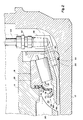
- the inner, non-rotational race 26 is shown mounted on the spindle 12 and sealed there against by the O-ring 33.
- the inner race 90 is formed with an axially extending air passage 98 to communicate the chamber 36 between the spindle 12 and the hub 14 with a collar, indicated generally at 100.
- the collar 100 is positioned inboard of the bearing set and mounted concentrically on the spindle.
Landscapes
- Engineering & Computer Science (AREA)
- Mechanical Engineering (AREA)
- General Engineering & Computer Science (AREA)
- Rolling Contact Bearings (AREA)
- Sealing Of Bearings (AREA)
- Vehicle Body Suspensions (AREA)
- Automatic Cycles, And Cycles In General (AREA)
- Automobile Manufacture Line, Endless Track Vehicle, Trailer (AREA)
Claims (50)
- Fahrzeugrad-Endanordnung zur Benutzung mit einem automatisierten System zum Kontrollieren des Reifendrucks, wobei die Anordnung eine sich nicht drehende Achse (12), eine Nabe (14), die eine Kammer (36) zwischen sich und der Achse zum Bilden eines Teil eines Luftweges begrenzt, der eine Verbindung zwischen dem automatisierten System und dem entsprechenden Reifen herstellt, Lagermittel (16, 18), die die Nabe drehbar auf der Achse halten, wobei die Lagermittel erste und zweite axial im Abstand angeordnete Lagersätze aufweisen, wobei jeder Lagersatz eine innere Laufbahn (20 oder 26) und eine äußere Laufbahn (22 oder 28) aufweist, und Drehdichtmittel (60, 62) aufweist, die arbeitsmäßig zwischen der Nabe und der Achse angeordnet sind, dadurch gekennzeichnet, daß wenigstens eine der Laufbahnen (z.B. 22 oder 28) so gestaltet ist, daß sie die Drehdichtmittel festlegt und einen Sitz dafür bildet.
- Radendanordnung nach Anspruch 1, dadurch gekennzeichnet, daß das Drehdichtmittel erste und zweite Dichtringe (60, 62) einschließt, wobei jeder Ring einen Flanschbereich (70) aufweist, und daß wenigstens eine Laufbahn (z.B. 28) mit einer lokalisierenden Aussparung (64) zum Festlegen des Flanschbereiches (70) des entsprechenden Dichtringes und zum Bilden eines Sitzes für denselben geformt ist.
- Radendanordnung nach Anspruch 2, dadurch gekennzeichnet, daß die äußere Laufbahn (z.B. 28) wenigstens eines der ersten und zweiten Lagersätze mit der lokalisierenden Ausnehmung (64) ausgebildet ist, und wobei die innere Laufbahn (26) des inneren Lagersatzes (18) einen Luftkanal (46) einschließt, der in Fluidverbindung mit der Nabenkammer (36) steht.
- Radendanordnung nach Anspruch 3, dadurch gekennzeichnet, daß sich der Luftkanal (46) allgemein axial durch die innere Laufbahn (26) erstreckt.
- Radendanordnung nach Anspruch 3, dadurch gekennzeichnet, daß jede äußere Laufbahn (22, 28) eine sich allgemein radial erstreckende Fläche aufweist, die zur Nabenkammer gerichtet ist, und daß die lokalisierende Ausnehmung in dieser Radialfläche ausgeformt ist.
- Radendanordnung nach Anspruch 2, dadurch gekennzeichnet, daß jede der inneren Laufbahnen (20, 26) der Lagersätze (16, 18) einen axialen Ansatz (68) aufweist, der zur Nabenkammer (36) gerichtet ist, wobei jeder der Dichtringe (60, 62) eine Lippe (72) aufweist, die den entsprechenden axialen Ansatz in dichtender Beziehung zu demselben berührt.
- Radendanordnung nach Anspruch 6, dadurch gekennzeichnet, daß die Lippe (72) in dichtender Beziehung an dem axialen Ansatz durch Vorspannungsmittel (78) festgehalten wird.
- Radendanordnung nach Anspruch 7, dadurch gekennzeichnet, daß die Vorspannungsmittel (78) eine Ringbandfeder aufweisen.
- Radendanordnung nach Anspruch 1, dadurch gekennzeichnet, daß die Nabe (14) zum Festlegen der Drehdichtmittel (60, 62) in fester Beziehung zu den Lagermitteln (16, 18) beiträgt.
- Radendanordnung nach Anspruch 1, dadurch gekennzeichnet, daß jede äußere Laufbahn (z.B. 22 oder 28) auch gegen die Nabe (14) abgedichtet ist.
- Radendanordnung nach Anspruch 1, dadurch gekennzeichnet, daß das Drehdichtmittel (60, 62) gegen die innere Laufbahn des entsprechenden Lagersatzes abdichtet.
- Radendanordnung nach Anspruch 11, dadurch gekennzeichnet, daß die innere Laufbahn (z.B. 26), einen radial sich erstreckenden Bereich (68) aufweist und das Drehdichtmittel (62) gegen den sich axial erstreckenden Bereich abdichtet.
- Radendanordnung nach Anspruch 11, dadurch gekennzeichnet, daß das Drehdichtmittel (z.B. 62) in einer Ausnehmung (64) an einem Ende der äußeren Laufbahn (28) befestigt ist.
- Radendanordnung nach Anspruch 11, dadurch gekennzeichnet, daß Mittel (z.B. 33) zum Abdichten der inneren Laufbahn 26 in Bezug auf die Achse (12) vorgesehen sind.
- Fahrzeugrad-Endanordnung zur Benutzung mit einem automatisierten System zum Kontrollieren des Reifendruckes, wobei die Anordnung eine Achse (12), eine Nabe (14), die eine Kammer (36) zwischen sich und der Achse begrenzt, wobei die Kammer Teil eines Luftweges für Verbindung zwischen dem automatisierten System und dem entsprechenden Reifen bildet, und Lagermittel (16, 18) aufweist, die die Nabe drehbar auf der Achse halten, dadurch gekennzeichnet, daß das Lagermittel einen Luftkanal (46) begrenzt, der an einem Ende mit der Kammer (36) in Verbindung steht und sich an seinem anderen Ende für Verbindung mit dem automatisierten System öffnet.
- Radendanordnung nach Anspruch 15, dadurch gekennzeichnet, daß das Lagermittel (16, 18) einen Lagersatz (18) einschließt, der im allgemeinen innen von der Nabenkammer (36) angeordnet ist und ein sich nicht drehendes Glied (28) aufweist, wobei der innere Luftkanal (46) in demselben ausgebildet ist.
- Radendanordnung nach Anspruch 16, dadurch gekennzeichnet, daß der Lagersatz (18) eine sich drehende äußere Anordnung (28), die mit der Nabe (14) verbunden ist, und eine sich nicht drehende innere Laufbahn (26) aufweist, die mit der Achse (12) verbunden ist, und wobei weiterhin der innere Luftkanal (46) innerhalb der inneren Laufbahn (26) ausgebildet ist.
- Radendanordnung nach einem der Ansprüche 15 bis 17, gekennzeichnet durch Mittel (62) zum Abdichten des Lagermittels (16, 18) in bezug auf die Achse (12) und die Nabe (14).
- Radendanordnung nach Anspruch 18, dadurch gekennzeichnet, daß das Dichtmittel ein Drehdichtmittel (62) aufweist, das mit der Nabe (14) und der Achse (12) verbunden ist, um eine abgedichtete Fluidverbindung der Nabenkammer (36) mit dem inneren Luftkanal (46) des Lagermittels zu bilden.
- Radendanordnung nach Anspruch 19, dadurch gekennzeichnet, daß das Drehdichtmittel (62) in fester Beziehung zum Lagermittel montiert ist.
- Radendanordnung nach Anspruch 20, bei dem die Nabe (14) zum Befestigen des Drehdichtmittels (62) in fester Beziehung zum Lagermittel beiträgt.
- Radendanordnung nach Anspruch 15, dadurch gekennzeichnet, daß ein Kragen (100 - Fig. 5) konzentrisch auf der Achse (12) befestigt ist und einen inneren Durchlaß (108, 114, 118) aufweist, der sich zwischen einer ersten Öffnung, die mit der Öffnung am anderen Ende des inneren Luftkanals (98) des Lagers in Verbindung steht, und einer zweiten Öffnung erstreckt, die mit dem automatisierten System verbunden ist.
- Radendanordnung nach Anspruch 22, dadurch gekennzeichnet, daß der Kragen (100) einen ringförmigen Körper (102) einschließt, der einen nach innen gerichteten radialen Flansch (104) aufweist.
- Radendanordnung nach Anspruch 23, dadurch gekennzeichnet, daß der Radialflansch (104) einstückig mit dem ringförmigen Körper (102) ausgebildet ist.
- Randendanordnung nach Anspruch 23, dadurch gekennzeichnet, daß die Achse (12) eine radiale Stufe (106) innen von der Nabe aufweist, die einen Sitz für den ringförmigen Körper (102) des Kragens bildet.
- Radendanordnung nach Anspruch 25, dadurch gekennzeichnet, daß der nach innen gerichtete radiale Flansch (104) außerhalb der radialen Stufe (106) angeordnet ist.
- Radendanordnung nach einem der Ansprüche 23 bis 26, dadurch gekennzeichnet, daß die erste Öffnung in der inneren Oberfläche des Flansches (104) und die zweite Öffnung in der äußeren Oberfläche des ringförmigen Körpers (102) ausgebildet ist.
- Radendanordnung nach einem der Ansprüche 23 bis 27, dadurch gekennzeichnet, daß Dichtmittel (105, 112) zum Abdichten der Verbindung der ersten Öffnung mit der Öffnung des inneren Luftkanals (98) des Lagers vorgesehen sind.
- Radendanordnung nach Anspruch 28, dadurch gekennzeichnet, daß das Dichtmittel (105, 112) erste und zweite O-Ringe aufweist, die in dichtender Beziehung zwischen den Dichtmitteln, der Achse und dem Kragen angeordnet sind.
- Radendanordnung nach Anspruch 29, dadurch gekennzeichnet, daß der erste O-Ring (112) dichtend an den Lagermitteln und dem Kragen angreift, und der zweite O-Ring (105) dichtend an dem Kragen und der Achse angreift.
- Radendanordnung nach Anspruch 30, dadurch gekennzeichnet, daß der Luftkanal (98) wenigstens teilweise durch wenigstens eine Umfangsausnehmung (111) in der inneren Laufbahn gebildet ist.
- Radendanordnung nach Anspruch 22, dadurch gekennzeichnet, daß Mittel (112) zum Dichten des Kragens gegen das Lagermittel über den Umfang der ersten Öffnung hinaus vorgesehen sind.
- Radendanordnung nach Anspruch 32, dadurch gekennzeichnet, daß das Lagermittel eine innere Laufbahn (90) und eine äußere Laufbahn (94) einschließt, und wobei das Dichtmittel (112) ein Dichtglied aufweist, das an der inneren Laufbahn und dem Kragen angreift.
- Radendanordnung nach Anspruch 22, dadurch gekennzeichnet, daß wenigstens ein Teil des Luftkanals (98) in dem Kragen sich durch einen nach innen gerichteten radialen Flansch (104) des ringförmigen Körpers erstreckt.
- Radendanordnung nach einem der Ansprüche 15 bis 34, gekennzeichnet durch Abstandshaltemittel (38), die zwischen der Nabe (14) und der Achse (12) angeordnet sind, um ein im wesentlichen konzentrisches Positionieren der Nabe während einer Relativbewegung der Nabe zur Achse aufrechtzuerhalten, um ein Abschaben der der Achse benachbarten Komponenten zu minimalisieren.
- Radendanordnung nach Anspruch 35, dadurch gekennzeichnet, daß das Abstandshaltemittel (38) konzentrisch in bezug auf die Achse (12) montiert ist.
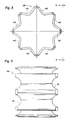
- Radendanordnung nach Anspruch 36, dadurch gekennzeichnet, daß das Abstandshaltemittel (38) im wesentlichen zylindrische Form mit radial sich wellender Oberfläche (40) hat.
- Radendanordnung nach Anspruch 36, dadurch gekennzeichnet, daß das Abstandshaltemittel (38) im wesentlichen zylindrische Form mit sich axial erstreckenden Zacken (41) hat.
- Verfahren bei einer Fahrzeugrad-Endanordnung, die für eine Benutzung mit einem automatisierten System zum Kontrollieren des Reifendrucks geeignet ist, wobei die Radendanordnung eine Achse (12) und eine Nabe (14) aufweist, die für Drehung auf der Achse montiert ist und dazwischen eine Kammer (36) begrenzt, um einen Teil eines Luftweges für Verbindung zwischen automatisiertem System und dem entsprechenden Reifen zu bilden, und wobei die Radanordnung Lagermittel (14, 16) zum drehenden Halten der Nabe auf der Achse in Arbeitsstellung zwischen der Achse und der Nabe aufweist, wobei bei dem Verfahren Druckluftkanäle in Verbindung mit dem Luftweg gebildet werden und das Verfahren die Schritte aufweist:(a) einen Lagersatz (18) zu installieren, der einen Luftdurchlaß (46) durch sich schafft; und(b) den Lagersatz (18) in bezug auf die Nabe (14) und die Achse (12) abzudichten.
- Verfahren nach Anspruch 39, dadurch gekennzeichnet, daß der Lagersatz (18) eine innere Laufbahn (26) und eine äußere Laufbahn (28) aufweist und der Schritt zum Installieren den Schritt einschließt, den Luftdurchlaß durch eine der Laufbahnen zu bilden.
- Verfahren nach Anspruch 40, dadurch gekennzeichnet, daß der Schritt zum Installieren weiter das Schaffen einer Umfangsausnehmung (64) in der einen Laufbahn einschließt.
- Verfahren nach Anspruch 39, dadurch gekennzeichnet, daß der Lagersatz (18) innere und äußere Laufbahnen (26, 28) einschließt, wobei der Abdichtschritt den Schritt einschließt, die inneren und äußeren Laufbahnen gegen die Achse (12) bzw. gegen die Nabe (14) abzudichten.
- Verfahren nach Anspruch 42, gekennzeichnet durch den Schritt, eine Drehdichtung (62) zwischen den inneren und äußeren Laufbahnen zu schaffen.
- Verfahren nach Anspruch 41, dadurch gekennzeichnet, daß der Lagersatz (18) innere und äußere Laufbahnen (26, 28) einschließt und daß der Schritt des Abdichtens den Schritt einschließt, die inneren und äußeren Laufbahnen gegen die Spindel bzw. gegen die Nabe abzudichten.
- Verfahren nach Anspruch 44, gekennzeichnet durch Installieren eines Kragens (100 - Fig. 5) auf der Achse, der einen Luftkanal (98) aufweist, der sich zwischen einer ersten Öffnung, die mit dem Luftweg in Verbindung steht, und einer zweiten Öffnung erstreckt, die mit dem automatisierten System in Verbindung steht.
- Verfahren nach Anspruch 45, dadurch gekennzeichnet, daß der Schritt, die innere Laufbahn (26) gegen die Achse abzudichten, die Schritte aufweist, die innere Laufbahn gegen den Kragen und den Kragen gegen die Spindel abzudichten.
- Verfahren nach Anspruch 39, dadurch gekennzeichnet, daß der Schritt des Installierens es einschließt, erste und zweite Lagersätze (16, 18) zu installieren und den Luftkanal durch nur einen der ersten und zweiten Lagersätze vorzusehen.
- Verfahren nach Anspruch 39, gekennzeichnet durch den Schritt, den Luftdurchlaß durch den Lagersitz vor dem Schritt des Installierens zu bilden.
- Fahrzeugrad-Endanordnung für Benutzung mit einem automatisierten System zum Kontrollieren des Reifenluftdrucks, wobei die Anordnung eine Achse (12), eine Nabe (14), die wenigstens einen Teil eines Luftweges für Verbindung zwischen dem automatisierten System und dem entsprechenden Reifen aufweist, Lagermittel (16, 18) zum drehenden Halten der Nabe auf der Achse, wobei die Lagermittel eine Laufbahn (z.B. 20) in Eingriff mit der Achse einschließen, und Drehdichtmittel (60, 62) aufweist, die zwischen der Nabe und der Achse angeordnet sind, dadurch gekennzeichnet, daß das Dichtmittel durch die Nabe gehalten ist und gegen die Laufbahn (z.B. 20) abdichtet.
- Fahrzeugrad-Endanordnung nach Anspruch 49, dadurch gekennzeichnet, daß das Lagermittel einen Durchlaß begrenzt, der einen anderen Teil des Luftweges bildet.
Priority Applications (1)
| Application Number | Priority Date | Filing Date | Title |
|---|---|---|---|
| AT86305274T ATE73059T1 (de) | 1985-07-08 | 1986-07-08 | Fahrzeugradanordnung. |
Applications Claiming Priority (2)
| Application Number | Priority Date | Filing Date | Title |
|---|---|---|---|
| US752576 | 1985-07-08 | ||
| US06/752,576 US4730656A (en) | 1985-07-08 | 1985-07-08 | Vehicle wheel end assembly |
Publications (3)
| Publication Number | Publication Date |
|---|---|
| EP0208540A2 EP0208540A2 (de) | 1987-01-14 |
| EP0208540A3 EP0208540A3 (en) | 1988-08-31 |
| EP0208540B1 true EP0208540B1 (de) | 1992-03-04 |
Family
ID=25026880
Family Applications (1)
| Application Number | Title | Priority Date | Filing Date |
|---|---|---|---|
| EP86305274A Expired - Lifetime EP0208540B1 (de) | 1985-07-08 | 1986-07-08 | Fahrzeugradanordnung |
Country Status (6)
| Country | Link |
|---|---|
| US (1) | US4730656A (de) |
| EP (1) | EP0208540B1 (de) |
| JP (2) | JPH0723043B2 (de) |
| AT (1) | ATE73059T1 (de) |
| CA (1) | CA1266423A (de) |
| DE (1) | DE3684048D1 (de) |
Cited By (1)
| Publication number | Priority date | Publication date | Assignee | Title |
|---|---|---|---|---|
| DE102005012277B4 (de) * | 2005-03-17 | 2025-11-13 | Ab Skf | Lageranordnung |
Families Citing this family (42)
| Publication number | Priority date | Publication date | Assignee | Title |
|---|---|---|---|---|
| US5236028A (en) * | 1985-07-08 | 1993-08-17 | Am General Corporation | Vehicle wheel end assembly |
| US4730656A (en) * | 1985-07-08 | 1988-03-15 | Am General Corporation | Vehicle wheel end assembly |
| US4804027A (en) * | 1987-09-17 | 1989-02-14 | Eaton Corporation | Axle and wheel assembly |
| JPH01101902U (de) * | 1987-12-26 | 1989-07-10 | ||
| US5080156A (en) * | 1990-02-12 | 1992-01-14 | Bartos Josef A | Vehicle wheel and axle assembly for controlling air pressure in tires with spaces between the bearing elements and the race members included in the air flow path |
| US5203391A (en) * | 1991-03-15 | 1993-04-20 | The Timken Company | Wheel mounting for tire pressure adjustment system |
| US5174839A (en) * | 1991-07-05 | 1992-12-29 | Eaton Corporation | Drive axle sleeve and seal assembly |
| JPH0554767U (ja) * | 1991-12-25 | 1993-07-23 | 甫之 榎並 | 2段式駐車装置 |
| US5429167A (en) * | 1993-08-13 | 1995-07-04 | Oshkosh Truck Corporation | Universal central tire inflation system for trailers |
| FR2727175B1 (fr) | 1994-11-17 | 1997-01-03 | Skf France | Roulement equipe d'un dispositif d'etancheite pour passage de fluide |
| US5823541A (en) * | 1996-03-12 | 1998-10-20 | Kalsi Engineering, Inc. | Rod seal cartridge for progressing cavity artificial lift pumps |
| US5954084A (en) * | 1996-04-08 | 1999-09-21 | Conroy, Sr.; Joseph P. | Pneumatic control |
| US6161565A (en) * | 1996-04-08 | 2000-12-19 | Conroy, Sr.; Joseph P. | Pneumatic control |
| US5832951A (en) * | 1996-04-08 | 1998-11-10 | Conroy, Sr.; Joseph P. | Pneumatic control |
| FR2750082A1 (fr) * | 1996-06-25 | 1997-12-26 | Michelin & Cie | Ensemble moyeu et porte-moyeu pour vehicule equipe d'un systeme de gonflage centralise |
| US6145558A (en) * | 1998-12-10 | 2000-11-14 | Case Corporation | Seal arrangement for a central tire inflation system |
| CA2335691C (en) * | 2001-03-01 | 2002-11-05 | Av Cell Inc. | Pressurized chamber seal cartridge |
| ITTO20020189A1 (it) | 2002-03-06 | 2003-09-08 | Skf Ind Spa | Dispositivo per l'alimentazione di aria compressa al pneumatico dellaruota di un veicolo attraverso il mozzo. |
| ITTO20020442A1 (it) * | 2002-05-24 | 2003-11-24 | Skf Ind Spa | Sistema per l'alimentazione di aria compressa ad un pneumatico di un veicolo attraverso il mozzo della ruota. |
| ITTO20020464A1 (it) | 2002-05-31 | 2003-12-01 | Skf Ind Spa | Unita' cuscinetto per il mozzo della ruota di un veicolo equiupaggiato di un sistema per il gonfiaggio dei pneumatici. |
| ITTO20020463A1 (it) * | 2002-05-31 | 2003-12-01 | Skf Ind Spa | Unita' cuscinetto per il mozzo della ruota di un veicolo equipaggiatodi un sistema per il gonfiaggio dei pneumatici. |
| US7740036B2 (en) | 2003-02-28 | 2010-06-22 | Air Tight, Llc | Pressurized wheel hub system |
| US7125084B2 (en) * | 2003-02-28 | 2006-10-24 | Air Tight | Environment protector-pressurized wheel hub |
| US8205526B2 (en) * | 2003-02-28 | 2012-06-26 | Henry Dombroski | Pressurized hub system |
| FR2862570A1 (fr) * | 2003-11-21 | 2005-05-27 | Skf Ind Spa | Dispositif pour delivrer de l'air sous pression a un pneu de vehicule |
| US7185688B2 (en) * | 2004-01-27 | 2007-03-06 | Arvinmeritor Technology, Llc | Central tire inflation system for drive axle |
| WO2007068275A1 (en) * | 2005-12-17 | 2007-06-21 | Ab Skf | Bearing arrangement |
| DE102008062740A1 (de) * | 2008-12-17 | 2010-05-12 | Ab Skf | Lageranordnung mit mindestens zwei sich in axialem Abstand befindlichen Lagern |
| US8931534B2 (en) * | 2010-03-10 | 2015-01-13 | Accuride Corporation | Vehicle wheel assemblies and valves for use with a central tire inflation system |
| CN102069680A (zh) * | 2011-01-06 | 2011-05-25 | 中国重汽集团济南动力有限公司 | 一种轮胎中央充放气结构用桥 |
| WO2012159779A1 (de) * | 2011-05-23 | 2012-11-29 | Schaeffler Technologies AG & Co. KG | Wälzlageranordnung mit formschluss unterstützendem verspannungsmittel |
| US9126460B2 (en) | 2012-03-02 | 2015-09-08 | Dana Heavy Vehicle Systems Group, Llc | Tire inflation system having a sleeve shaped air passage |
| RU2592976C2 (ru) | 2012-04-06 | 2016-07-27 | Дана Хеви Виикл Системз Груп, Ллк | Система подкачки шин |
| WO2013154976A1 (en) | 2012-04-09 | 2013-10-17 | Dana Heavy Vehicle Systems Group, Llc | Tire inflation system |
| US10059156B2 (en) | 2012-04-09 | 2018-08-28 | Dana Heavy Vehicle Systems Group, Llc | Hub assembly for a tire inflation system |
| EP2653323B1 (de) * | 2012-04-19 | 2016-03-23 | DANA ITALIA S.p.A | Achsanordnung für Reifenfüllsystem |
| US9539865B2 (en) * | 2013-10-10 | 2017-01-10 | Arvinmeritor Technology, Llc | Tire inflation system having a sleeve assembly for routing pressurized gas |
| EP3164273B1 (de) | 2014-07-02 | 2018-09-12 | DANA ITALIA S.p.A | Drehdichtung für eine zentrale reifenaufpumpanlage |
| WO2017070325A1 (en) | 2015-10-20 | 2017-04-27 | Dana Heavy Vehicle Systems Group, Llc | Wheel end assembly for a tire inflation system and the tire inflation system made therewith |
| US10052913B2 (en) | 2016-11-09 | 2018-08-21 | Arvinmeritor Technology, Llc | Wheel end assembly having a seal interface with a tone ring |
| US10293636B2 (en) | 2017-05-03 | 2019-05-21 | Arvinmeritor Technology, Llc | Wheel end assembly having a deflector |
| US10899174B2 (en) | 2018-03-15 | 2021-01-26 | Arvinmeritor Technology, Llc | Wheel end assembly having a compression ring and method of assembly |
Family Cites Families (12)
| Publication number | Priority date | Publication date | Assignee | Title |
|---|---|---|---|---|
| US2634783A (en) * | 1950-10-30 | 1953-04-14 | Bendix Westinghouse Automotive | Tire inflation control system |
| GB1168394A (en) * | 1968-02-06 | 1969-10-22 | Rolls Royce | Bearing Assembly |
| DE1938202A1 (de) * | 1969-07-28 | 1971-02-11 | Graubremse Gmbh | An eine fahrzeugeigene Reifenfuelleinrichtung anzuschliessendes luftbereiftes Fahrzeugrad |
| US4015883A (en) * | 1973-10-23 | 1977-04-05 | Skf Industrial Trading And Development Company, B.V. | Annular sealing members and assemblies incorporating them |
| JPS5436820Y2 (de) * | 1977-06-10 | 1979-11-06 | ||
| JPS5551123A (en) * | 1978-10-02 | 1980-04-14 | Hitachi Ltd | Dust protective device for bearing |
| US4293061A (en) * | 1979-07-11 | 1981-10-06 | The Bendix Corporation | Remote controlled hub clutch |
| JPS5628006U (de) * | 1979-08-08 | 1981-03-16 | ||
| US4431043A (en) * | 1981-07-31 | 1984-02-14 | Am General Corporation | Automatic tire inflation system |
| NL8302055A (nl) * | 1983-06-09 | 1985-01-02 | Skf Ind Trading & Dev | Afdichtring voor een wentellager. |
| US4498709A (en) * | 1983-06-30 | 1985-02-12 | Rockwell International Corporation | Axle for use with a tire inflation system |
| US4730656A (en) * | 1985-07-08 | 1988-03-15 | Am General Corporation | Vehicle wheel end assembly |
-
1985
- 1985-07-08 US US06/752,576 patent/US4730656A/en not_active Expired - Lifetime
-
1986
- 1986-07-07 CA CA000513188A patent/CA1266423A/en not_active Expired - Lifetime
- 1986-07-08 JP JP61160673A patent/JPH0723043B2/ja not_active Expired - Lifetime
- 1986-07-08 AT AT86305274T patent/ATE73059T1/de not_active IP Right Cessation
- 1986-07-08 DE DE8686305274T patent/DE3684048D1/de not_active Expired - Lifetime
- 1986-07-08 EP EP86305274A patent/EP0208540B1/de not_active Expired - Lifetime
-
1990
- 1990-08-06 JP JP2207957A patent/JP2740341B2/ja not_active Expired - Lifetime
Cited By (1)
| Publication number | Priority date | Publication date | Assignee | Title |
|---|---|---|---|---|
| DE102005012277B4 (de) * | 2005-03-17 | 2025-11-13 | Ab Skf | Lageranordnung |
Also Published As
| Publication number | Publication date |
|---|---|
| JPH03104703A (ja) | 1991-05-01 |
| ATE73059T1 (de) | 1992-03-15 |
| US4730656A (en) | 1988-03-15 |
| EP0208540A2 (de) | 1987-01-14 |
| JP2740341B2 (ja) | 1998-04-15 |
| JPS6277203A (ja) | 1987-04-09 |
| JPH0723043B2 (ja) | 1995-03-15 |
| CA1266423A (en) | 1990-03-06 |
| EP0208540A3 (en) | 1988-08-31 |
| DE3684048D1 (de) | 1992-04-09 |
Similar Documents
| Publication | Publication Date | Title |
|---|---|---|
| EP0208540B1 (de) | Fahrzeugradanordnung | |
| US5354391A (en) | Vehicle wheel end assembly | |
| US4733707A (en) | Vehicle wheel end assembly | |
| EP0575525B1 (de) | Radbefestigung für eine reifendruckregelungsanlage | |
| US5080156A (en) | Vehicle wheel and axle assembly for controlling air pressure in tires with spaces between the bearing elements and the race members included in the air flow path | |
| EP0410723B1 (de) | Dichtvorrichtung für eine Reifendruckregelungsanlage | |
| EP0379355B1 (de) | Rotierendes Gelenk für eine Reifendruckregelanlage | |
| US5979526A (en) | Hub and hub-holder assembly for vehicles equipped with a central tire inflation system | |
| US5080157A (en) | Seal for use between relatively rotating members | |
| EP0521719B1 (de) | Hülse mit Abdichtungsanordnung für eine Antriebswelle | |
| US6439044B1 (en) | Rotary transmission leadthrough of a tire pressure control unit | |
| US4892128A (en) | Vehicle wheel seal assembly | |
| US6145558A (en) | Seal arrangement for a central tire inflation system | |
| US11014401B2 (en) | Hub cap assembly with sight glass | |
| US3841723A (en) | Railway bearing seal | |
| US20200094621A1 (en) | Axle assembly and the tire inflation system made therewith | |
| GB2177465A (en) | Sliding ring seal | |
| US6220325B1 (en) | Air guide for a tire pressure regulating device | |
| US4241957A (en) | Wheel bearing slinger ring | |
| US11454322B2 (en) | Rotary pneumatic seal for a central tire inflation system | |
| EP4155564A1 (de) | Dichtungsvorrichtung | |
| RU2821606C1 (ru) | Вращающееся устройство сквозной подачи, предназначенное, в частности, для регулирования давления в шине | |
| US20250346076A1 (en) | Track widener for inflating/deflating tyres of a vehicle | |
| EP4192697B1 (de) | Drehdurchführung, insbesondere zur reifendruckregelung | |
| JPH0228081Y2 (de) |
Legal Events
| Date | Code | Title | Description |
|---|---|---|---|
| PUAI | Public reference made under article 153(3) epc to a published international application that has entered the european phase |
Free format text: ORIGINAL CODE: 0009012 |
|
| AK | Designated contracting states |
Kind code of ref document: A2 Designated state(s): AT DE FR GB IT SE |
|
| PUAL | Search report despatched |
Free format text: ORIGINAL CODE: 0009013 |
|
| AK | Designated contracting states |
Kind code of ref document: A3 Designated state(s): AT DE FR GB IT SE |
|
| 17P | Request for examination filed |
Effective date: 19890215 |
|
| 17Q | First examination report despatched |
Effective date: 19900504 |
|
| GRAA | (expected) grant |
Free format text: ORIGINAL CODE: 0009210 |
|
| AK | Designated contracting states |
Kind code of ref document: B1 Designated state(s): AT DE FR GB IT SE |
|
| REF | Corresponds to: |
Ref document number: 73059 Country of ref document: AT Date of ref document: 19920315 Kind code of ref document: T |
|
| REF | Corresponds to: |
Ref document number: 3684048 Country of ref document: DE Date of ref document: 19920409 |
|
| ITF | It: translation for a ep patent filed | ||
| ET | Fr: translation filed | ||
| PLBE | No opposition filed within time limit |
Free format text: ORIGINAL CODE: 0009261 |
|
| STAA | Information on the status of an ep patent application or granted ep patent |
Free format text: STATUS: NO OPPOSITION FILED WITHIN TIME LIMIT |
|
| 26N | No opposition filed | ||
| EAL | Se: european patent in force in sweden |
Ref document number: 86305274.2 |
|
| REG | Reference to a national code |
Ref country code: GB Ref legal event code: IF02 |
|
| PGFP | Annual fee paid to national office [announced via postgrant information from national office to epo] |
Ref country code: AT Payment date: 20050621 Year of fee payment: 20 |
|
| PGFP | Annual fee paid to national office [announced via postgrant information from national office to epo] |
Ref country code: GB Payment date: 20050629 Year of fee payment: 20 |
|
| PGFP | Annual fee paid to national office [announced via postgrant information from national office to epo] |
Ref country code: FR Payment date: 20050718 Year of fee payment: 20 |
|
| PGFP | Annual fee paid to national office [announced via postgrant information from national office to epo] |
Ref country code: SE Payment date: 20050720 Year of fee payment: 20 |
|
| PGFP | Annual fee paid to national office [announced via postgrant information from national office to epo] |
Ref country code: IT Payment date: 20050728 Year of fee payment: 20 |
|
| REG | Reference to a national code |
Ref country code: GB Ref legal event code: PE20 |
|
| PGFP | Annual fee paid to national office [announced via postgrant information from national office to epo] |
Ref country code: DE Payment date: 20050831 Year of fee payment: 20 |
|
| PG25 | Lapsed in a contracting state [announced via postgrant information from national office to epo] |
Ref country code: GB Free format text: LAPSE BECAUSE OF EXPIRATION OF PROTECTION Effective date: 20060707 |
|
| EUG | Se: european patent has lapsed |