EP3164273B1 - Drehdichtung für eine zentrale reifenaufpumpanlage - Google Patents
Drehdichtung für eine zentrale reifenaufpumpanlage Download PDFInfo
- Publication number
- EP3164273B1 EP3164273B1 EP15733458.2A EP15733458A EP3164273B1 EP 3164273 B1 EP3164273 B1 EP 3164273B1 EP 15733458 A EP15733458 A EP 15733458A EP 3164273 B1 EP3164273 B1 EP 3164273B1
- Authority
- EP
- European Patent Office
- Prior art keywords
- rotary seal
- seal arrangement
- bushing
- sealing ring
- stationary
- Prior art date
- Legal status (The legal status is an assumption and is not a legal conclusion. Google has not performed a legal analysis and makes no representation as to the accuracy of the status listed.)
- Active
Links
- 238000007789 sealing Methods 0.000 claims description 154
- 239000012530 fluid Substances 0.000 claims description 29
- 238000004891 communication Methods 0.000 claims description 17
- 239000000428 dust Substances 0.000 claims description 16
- 239000000463 material Substances 0.000 description 18
- 241001185540 Charissa ambiguata Species 0.000 description 9
- 239000002783 friction material Substances 0.000 description 6
- 238000004519 manufacturing process Methods 0.000 description 5
- 239000002184 metal Substances 0.000 description 4
- 230000005540 biological transmission Effects 0.000 description 3
- 230000015572 biosynthetic process Effects 0.000 description 2
- 239000002699 waste material Substances 0.000 description 2
- 238000005056 compaction Methods 0.000 description 1
- 230000003247 decreasing effect Effects 0.000 description 1
- 238000010586 diagram Methods 0.000 description 1
- 239000000446 fuel Substances 0.000 description 1
- 230000010354 integration Effects 0.000 description 1
- 238000000034 method Methods 0.000 description 1
- 238000004321 preservation Methods 0.000 description 1
- 239000002689 soil Substances 0.000 description 1
Images


Classifications
-
- B—PERFORMING OPERATIONS; TRANSPORTING
- B60—VEHICLES IN GENERAL
- B60C—VEHICLE TYRES; TYRE INFLATION; TYRE CHANGING; CONNECTING VALVES TO INFLATABLE ELASTIC BODIES IN GENERAL; DEVICES OR ARRANGEMENTS RELATED TO TYRES
- B60C23/00—Devices for measuring, signalling, controlling, or distributing tyre pressure or temperature, specially adapted for mounting on vehicles; Arrangement of tyre inflating devices on vehicles, e.g. of pumps or of tanks; Tyre cooling arrangements
- B60C23/001—Devices for manually or automatically controlling or distributing tyre pressure whilst the vehicle is moving
- B60C23/003—Devices for manually or automatically controlling or distributing tyre pressure whilst the vehicle is moving comprising rotational joints between vehicle-mounted pressure sources and the tyres
- B60C23/00309—Devices for manually or automatically controlling or distributing tyre pressure whilst the vehicle is moving comprising rotational joints between vehicle-mounted pressure sources and the tyres characterised by the location of the components, e.g. valves, sealings, conduits or sensors
- B60C23/00318—Devices for manually or automatically controlling or distributing tyre pressure whilst the vehicle is moving comprising rotational joints between vehicle-mounted pressure sources and the tyres characterised by the location of the components, e.g. valves, sealings, conduits or sensors on the wheels or the hubs
-
- B—PERFORMING OPERATIONS; TRANSPORTING
- B60—VEHICLES IN GENERAL
- B60C—VEHICLE TYRES; TYRE INFLATION; TYRE CHANGING; CONNECTING VALVES TO INFLATABLE ELASTIC BODIES IN GENERAL; DEVICES OR ARRANGEMENTS RELATED TO TYRES
- B60C23/00—Devices for measuring, signalling, controlling, or distributing tyre pressure or temperature, specially adapted for mounting on vehicles; Arrangement of tyre inflating devices on vehicles, e.g. of pumps or of tanks; Tyre cooling arrangements
- B60C23/001—Devices for manually or automatically controlling or distributing tyre pressure whilst the vehicle is moving
- B60C23/003—Devices for manually or automatically controlling or distributing tyre pressure whilst the vehicle is moving comprising rotational joints between vehicle-mounted pressure sources and the tyres
- B60C23/00345—Details of the rotational joints
-
- B—PERFORMING OPERATIONS; TRANSPORTING
- B60—VEHICLES IN GENERAL
- B60C—VEHICLE TYRES; TYRE INFLATION; TYRE CHANGING; CONNECTING VALVES TO INFLATABLE ELASTIC BODIES IN GENERAL; DEVICES OR ARRANGEMENTS RELATED TO TYRES
- B60C23/00—Devices for measuring, signalling, controlling, or distributing tyre pressure or temperature, specially adapted for mounting on vehicles; Arrangement of tyre inflating devices on vehicles, e.g. of pumps or of tanks; Tyre cooling arrangements
- B60C23/001—Devices for manually or automatically controlling or distributing tyre pressure whilst the vehicle is moving
- B60C23/003—Devices for manually or automatically controlling or distributing tyre pressure whilst the vehicle is moving comprising rotational joints between vehicle-mounted pressure sources and the tyres
- B60C23/00363—Details of sealings
-
- B—PERFORMING OPERATIONS; TRANSPORTING
- B60—VEHICLES IN GENERAL
- B60C—VEHICLE TYRES; TYRE INFLATION; TYRE CHANGING; CONNECTING VALVES TO INFLATABLE ELASTIC BODIES IN GENERAL; DEVICES OR ARRANGEMENTS RELATED TO TYRES
- B60C23/00—Devices for measuring, signalling, controlling, or distributing tyre pressure or temperature, specially adapted for mounting on vehicles; Arrangement of tyre inflating devices on vehicles, e.g. of pumps or of tanks; Tyre cooling arrangements
- B60C23/001—Devices for manually or automatically controlling or distributing tyre pressure whilst the vehicle is moving
- B60C23/003—Devices for manually or automatically controlling or distributing tyre pressure whilst the vehicle is moving comprising rotational joints between vehicle-mounted pressure sources and the tyres
- B60C23/00372—Devices for manually or automatically controlling or distributing tyre pressure whilst the vehicle is moving comprising rotational joints between vehicle-mounted pressure sources and the tyres characterised by fluid diagrams
-
- F—MECHANICAL ENGINEERING; LIGHTING; HEATING; WEAPONS; BLASTING
- F16—ENGINEERING ELEMENTS AND UNITS; GENERAL MEASURES FOR PRODUCING AND MAINTAINING EFFECTIVE FUNCTIONING OF MACHINES OR INSTALLATIONS; THERMAL INSULATION IN GENERAL
- F16J—PISTONS; CYLINDERS; SEALINGS
- F16J15/00—Sealings
- F16J15/16—Sealings between relatively-moving surfaces
- F16J15/34—Sealings between relatively-moving surfaces with slip-ring pressed against a more or less radial face on one member
-
- F—MECHANICAL ENGINEERING; LIGHTING; HEATING; WEAPONS; BLASTING
- F16—ENGINEERING ELEMENTS AND UNITS; GENERAL MEASURES FOR PRODUCING AND MAINTAINING EFFECTIVE FUNCTIONING OF MACHINES OR INSTALLATIONS; THERMAL INSULATION IN GENERAL
- F16L—PIPES; JOINTS OR FITTINGS FOR PIPES; SUPPORTS FOR PIPES, CABLES OR PROTECTIVE TUBING; MEANS FOR THERMAL INSULATION IN GENERAL
- F16L27/00—Adjustable joints, Joints allowing movement
- F16L27/08—Adjustable joints, Joints allowing movement allowing adjustment or movement only about the axis of one pipe
- F16L27/0804—Adjustable joints, Joints allowing movement allowing adjustment or movement only about the axis of one pipe the fluid passing axially from one joint element to another
Definitions
- the present invention relates to tire inflation systems and more specifically to tire inflation systems having rotary seals external to an axle.
- Tire inflation systems are becoming crucial in motor vehicles. Those systems are deeply adopted in different types of vehicles such as trucks, tractors or earth-moving machines.
- a main objective of a tire inflation system is to adapt the tire pressure to different operating conditions, which depends basically on the ground to be traveled as well as a speed and a load of a vehicle using the tire inflation system.
- a contact area of a tire is influenced by a pressure of the tire. With a low tire pressure the contact area is increased, and with a high tire pressure the contact area is decreased. For this reason, it is necessary to optimize a tire pressure depending on the ground conditions.
- a lower pressure is adopted for soft surfaces such as gravel, while a higher pressure is chosen when traveling on hard surfaces, such as tarmac or concrete.
- appropriate tire pressure can provide enhanced tire preservation, reduced soil compaction, improved fuel consumption, and reduced overall operating costs.
- FIG. 1 illustrates a central tire inflation system (CTIS) 50 that is known in the art. It is understood that the CTIS 50 is exemplary in nature, and that the CTIS 50 may be adapted through the addition or removal of components.
- the CTIS 50 is a system for inflating or deflating one or more tires 52, depending on a ground condition.
- the CTIS 50 is comprised of several components and devices, as shown in FIG. 1 .
- An air compressor 54 which provides pressurized air, is fitted to a vehicle 56. The compressed air passes through an air dryer 58 and is stored in an air tank 60. Based on an input coming from a driver of the vehicle 56 or from an internal algorithm of an electronic control unit (ECU) 62, a pneumatic control unit 64 provides air flow to the tires 52.
- ECU electronice control unit
- the CTIS 50 also typically comprises a rotary transmission joint 68 which allows for compressed air to be transmitted from a portion of the CTIS 50 on the vehicle 56 to each of the tires 52, which are rotatably.
- the rotary transmission joint 68 affords fluid communication for each of the tire 52.
- Such a rotary transmission joint 68 typically comprises a stator structural group coupled to the vehicle 56 and a rotor structural group located on the tire 52.
- tire inflation systems known from the prior art comprise rotary seal arrangements which are disposed between a vehicle spindle and a wheel hub, on which the wheel and the tire are mounted.
- rotary seals are the most critical devices in the CTIS 50, since they are required to transmit the fluid from the pneumatic line to the wheel valve 66 while rotating with the tire 52.
- These rotary seals usually include sealing means, disposed on the spindle and/or on the wheel hub, in sliding contact between each other. The sealing means, therefore, forms a dynamical annular seal chamber, through which fluid can be transported from the pneumatic control unit 64 to the tire 52 and vice versa.
- FR 2 874 671 A1 relates to a bearing having a path forming air passage with outer and inner channels.
- An annular chamber puts the channels in air communication.
- the chamber is formed between two adjacent joints associated to an inner rotating unit or an outer fixed unit.
- An annular deflector disposed inside the chamber is associated to the other of the units.
- the deflector has walls on which joints are in frictional contact.
- the inner rotating unit and the outer fixed unit have balls disposed between them.
- the outer and inner channels traverse respectively the units.
- the air path is formed inside the annular chamber through the deflector.
- the present invention is directed to a rotary seal arrangement for use with a central tire inflation system.
- the rotary seal arrangement comprises a stationary portion, a rotating portion, a first sealing ring, a second sealing ring, and a first bushing.
- the stationary portion defines a first air passage therethrough.
- the rotating portion defines a second air passage therethrough.
- the first sealing ring is disposed on one of the rotating portion and the stationary portion.
- the second sealing ring is disposed on one of the rotating portion and the stationary portion.
- the first bushing is disposed on one of the rotating portion and the stationary portion.
- the first bushing is in dynamic sealing engagement with the first sealing ring.
- the stationary portion, the rotating portion, the first sealing ring, and the second sealing ring form a sealed cavity that facilitates fluid communication between the first air passage and the second air passage.
- the present invention is directed to a rotary seal arrangement for use with a central tire inflation system.
- the rotary seal arrangement comprises a stationary portion, a rotating portion, a first sealing ring, a second sealing ring, a first bushing, and a second bushing.
- the stationary portion defines a first air passage therethrough.
- the stationary portion includes an external ring disposed thereon and coupled thereto.
- the rotating portion defines a second air passage therethrough.
- the first sealing ring is disposed on the rotating portion.
- the second sealing ring is disposed on the external ring.
- the first bushing is disposed on the stationary portion.
- the first bushing is in dynamic sealing engagement with the first sealing ring.
- the second bushing is disposed on the rotating portion.
- the second bushing is in dynamic sealing engagement with the second sealing ring.
- the stationary portion, the rotating portion, the first sealing ring, and the second sealing ring form a sealed cavity that facilitates fluid communication between the first air passage and the second air passage.
- the present invention is directed to a rotary seal arrangement for use with a central tire inflation system.
- the rotary seal arrangement comprises a stationary assembly, a rotating portion, a first sealing ring, a second sealing ring, a first bushing, and a second bushing.
- the stationary assembly comprises a main portion, a radially extending portion, and a seal engaging portion.
- the stationary assembly defines a first air passage therethrough.
- the rotating portion defines a second air passage therethrough.
- the first sealing ring is disposed on the seal engaging portion.
- the second sealing ring is disposed on the seal engaging portion.
- the first bushing is disposed on the rotating portion.
- the first bushing is in dynamic sealing engagement with the first sealing ring.
- the second bushing is disposed on the rotating portion.
- the second bushing is in dynamic sealing engagement with the second sealing ring.
- the stationary portion, the rotating portion, the first sealing ring, and the second sealing ring form a sealed cavity that facilitates fluid communication between the first air
- FIG. 2 illustrates a rotary seal arrangement 100 according to an embodiment of the invention.
- the rotary seal arrangement 100 comprises a rotating portion 102, a stationary portion 104, a first sealing ring 106, a first bushing 108, a second sealing ring 110, a second bushing 112, an external ring 114, and a breather 116.
- the first bushing 108 and the external ring 114 are disposed on the stationary portion 104.
- the first sealing ring 106 and the second bushing 112 are disposed on the rotating portion 102.
- the second sealing ring 110 is disposed on the external ring 114.
- the breather 116 is formed in the stationary portion 104.
- the rotating portion 102 may be a portion of a wheel hub or a portion of a shaft.
- the rotating portion 102 is typically cast and machined; however, it is understood that the rotating portion 102 may be formed in any manner.
- the rotating portion 102 defines a primary air passage 118 therethrough. As shown in FIG. 2 , the primary air passage 118 is formed by an intersection of three apertures formed in the rotating portion 102; however, it is understood that the primary air passage 118 may comprise any number of apertures formed in the rotating portion 102. As shown in FIG. 2 , at least one of the apertures may be plugged to facilitate formation of the primary air passage 118.
- the stationary portion 104 may be a portion of an axle housing or a portion of a steering knuckle.
- the stationary portion 104 is typically cast and machined; however, it is understood that the stationary portion 104 may be formed in any manner.
- the stationary portion 104 defines a secondary air passage 120 therethrough. As shown in FIG. 2 , the secondary air passage 120 is formed by an intersection of two apertures formed in the stationary portion 104; however, it is understood that the secondary air passage 120 may comprise any number of apertures formed in the stationary portion 104.
- the first sealing ring 106 facilitates dynamic sealing engagement between the rotating portion 102 and the first bushing 108.
- the first sealing ring 106 is a sealing assembly that militates against a transfer of air, oil, or dust between a sealed cavity 122 formed between the rotating portion 102 and the stationary portion 104 and an ambient environment the rotary seal arrangement 100 is operated in.
- At least a portion of the first sealing ring 106 is configured to provide a sealing force against the first bushing 108 in a radial manner.
- at least a portion of the first sealing ring 106 is formed from a polymeric material. The first sealing ring 106 efficiently separates the sealed cavity 122 intended for the air passage, from an inner operating environment between the rotating portion 102 and the stationary portion 104, avoiding air leakage.
- the first bushing 108 is an annulet disposed on and coupled to the stationary portion 104.
- the first bushing 108 provides a surface which can be dynamically sealingly engaged with the first sealing ring 106.
- the first bushing 108 is formed from a wear resistant, low friction material; however, it is understood that other material may be used.
- the second sealing ring 110 facilitates dynamic sealing engagement between the stationary portion 104 and the second bushing 112.
- the second sealing ring 110 is a sealing assembly that militates against a transfer of air, oil, or dust between the sealed cavity 122 formed between the rotating portion 102 and the stationary portion 104 and an ambient environment the rotary seal arrangement 100 is operated in.
- At least a portion of the second sealing ring 110 is configured to provide a sealing force against the second bushing 112 in a radial manner.
- at least a portion of the second sealing ring 110 is formed from a polymeric material. The second sealing ring 110 efficiently separates the sealed cavity 122 intended for the air passage, from the ambient environment the rotary seal arrangement 100 is operated in, avoiding air leakage.
- the second bushing 112 is an annulet disposed on and coupled to the rotating portion 102.
- the second bushing 112 provides a surface which can be dynamically sealingly engaged with the second sealing ring 110.
- the second bushing 112 is formed from a wear resistant, low friction material; however, it is understood that other material may be used.
- the external ring 114 is an annulet disposed on and coupled to the stationary portion 104.
- the external ring 114 is coupled to the stationary portion 104 in any conventional manner.
- the external ring 114 provides a surface onto which the second sealing ring 110 can be mounted.
- the external ring 114 is formed from a metal; however, it is understood that other rigid materials may be used.
- a cross-section of the external ring 114 is substantially "L" shaped; however, it is understood that the cross-section of the external ring 114 may have other shapes.
- the breather 116 is a conduit defined by the stationary portion 104.
- the breather 116 is positioned adjacent the first bushing 108.
- the breather 116 includes an exhaust valve which facilitates fluid communication between the inner operating environment between the rotating portion 102 and the stationary portion 104 and the ambient environment the rotary seal arrangement 100 is operated in, in the event of fluid leakage from the inner operating environment.
- FIG. 3 illustrates a rotary seal arrangement 200 according to an embodiment of the invention.
- the embodiment shown in FIG. 3 includes similar components to the rotary seal arrangement 100 illustrated in FIG. 2 . Similar features of the embodiment shown in FIG. 3 are numbered similarly in series, with the exception of the features described below.
- FIG. 3 illustrates the rotary seal arrangement 200 according to an embodiment of the invention.
- the rotary seal arrangement 200 comprises a rotating portion 202, a stationary portion 204, a first sealing ring 206, a first bushing 208, a second sealing ring 230, a second bushing 212, an external ring 214, and a breather 216.
- the first bushing 208 and the external ring 214 are disposed on the stationary portion 204.
- the first sealing ring 206 and the second bushing 212 are disposed on the rotating portion 202.
- the second sealing ring 230 is disposed on the external ring 214.
- the breather 216 is formed in the stationary portion 204.
- the second sealing ring 230 facilitates dynamic sealing engagement between the stationary portion 204 and the second bushing 212.
- the second sealing ring 230 is a sealing assembly that militates against a transfer of air, oil, or dust between the sealed cavity 222 formed between the rotating portion 202 and the stationary portion 204 and an ambient environment the rotary seal arrangement 200 is operated in.
- At least a portion of the second sealing ring 230 is configured to provide a sealing force against the second bushing 212 in a radial manner.
- at least a portion of the second sealing ring 230 is formed from a polymeric material. The second sealing ring 230 efficiently separates the sealed cavity 222 intended for the air passage, from an inner operating environment between the rotating portion 202 and the stationary portion 204, avoiding air leakage.
- the breather 216 is a conduit defined by the stationary portion 204.
- the breather 216 is positioned adjacent the first bushing 208.
- the breather 216 includes an exhaust valve which facilitates fluid communication between the inner operating environment between the rotating portion 202 and the stationary portion 204 and the ambient environment the rotary seal arrangement 200 is operated in, in the event of fluid leakage from the inner operating environment.
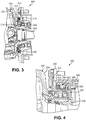
- FIG. 4 illustrates a rotary seal arrangement 300 according to an embodiment of the invention.
- the embodiment shown in FIG. 4 includes similar components to the rotary seal arrangement 100 illustrated in FIG. 2 . Similar features of the embodiment shown in FIG. 4 are numbered similarly in series, with the exception of the features described below.
- FIG. 4 illustrates the rotary seal arrangement 300 according to an embodiment of the invention.
- the rotary seal arrangement 300 comprises a rotating portion 340, a stationary assembly 342, a first sealing ring 344, a first bushing 346, a second sealing ring 348, and a second bushing 350.
- the first bushing 346 and the second bushing 350 are disposed on the rotating portion 340.
- the first sealing ring 344 and the second sealing ring 348 are disposed on the stationary assembly 342.
- the rotating portion 340 may be a portion of a wheel hub or a portion of a shaft.
- the rotating portion 340 is typically cast and machined; however, it is understood that the rotating portion 340 may be formed in any manner.
- the rotating portion 340 defines a primary air passage 352 therethrough. As shown in FIG. 4 , the primary air passage 352 is formed by an intersection of four apertures formed in the rotating portion 340; however, it is understood that the primary air passage 352 may comprise any number of apertures formed in the rotating portion 340. As shown in FIG. 4 , at least two of the apertures may be plugged to facilitate formation of the primary air passage 352.
- the stationary assembly 342 may be a portion of an axle housing or a portion of a steering knuckle.
- the stationary assembly 342 is typically formed from cast and machined bodies; however, it is understood that the stationary assembly 342 may be formed in any manner.
- the stationary assembly 342 comprises a main portion 354, a radially extending portion 356, and a seal engaging portion 358.
- the radially extending portion 356 is coupled to and sealingly engaged with the main portion 354 in any conventional manner, after the rotating portion 340 is disposed about the main portion 354.
- the seal engaging portion 358 is coupled to and sealingly engaged with the radially extending portion 356 in any conventional manner.
- the stationary assembly 342 defines a secondary air passage 360 therethrough. As shown in FIG.
- the secondary air passage 360 is formed by an intersection of ten apertures formed in the main portion 354, the radially extending portion 356, and the seal engaging portion 358; however, it is understood that the secondary air passage 360 may comprise any number of apertures formed in the main portion 354, the radially extending portion 356, and the seal engaging portion 358.
- the first sealing ring 344 facilitates dynamic sealing engagement between the seal engaging portion 358 and the first bushing 346.
- the first sealing ring 344 is a sealing assembly that militates against a transfer of air, oil, or dust between a sealed cavity 362 formed between the stationary assembly 342 and the rotating portion 340 and an ambient environment the rotary seal arrangement 300 is operated in. At least a portion of the first sealing ring 344 is configured to provide a sealing force against the first bushing 346 in a radial manner. Further, at least a portion of the first sealing ring 344 is formed from a polymeric material. The first sealing ring 344 efficiently separates the sealed cavity 362 intended for the air passage, from an inner operating environment between the rotating portion 340 and the stationary assembly 342, avoiding air leakage.
- the first bushing 346 is an annulet disposed on and coupled to the rotating portion 340.
- the first bushing 346 provides a surface which can be dynamically sealingly engaged with the first sealing ring 344.
- the first bushing 346 is formed from a wear resistant, low friction material; however, it is understood that other material may be used.
- the second sealing ring 348 facilitates dynamic sealing engagement between the seal engaging portion 358 and the second bushing 350.
- the second sealing ring 348 is a sealing assembly that militates against a transfer of air, oil, or dust between the sealed cavity 362 formed between the stationary assembly 342 and the rotating portion 340 and an ambient environment the rotary seal arrangement 300 is operated in.
- At least a portion of the second sealing ring 348 is configured to provide a sealing force against the second bushing 350 in a radial manner.
- at least a portion of the second sealing ring 348 is formed from a polymeric material. The second sealing ring 348 efficiently separates the sealed cavity 362 intended for the air passage, from an inner operating environment between the rotating portion 340 and the stationary assembly 342, avoiding air leakage.
- the second bushing 350 is an annulet disposed on and coupled to the rotating portion 340.
- the second bushing 350 provides a surface which can be dynamically sealingly engaged with the second sealing ring 348.
- the second bushing 350 is formed from a wear resistant, low friction material; however, it is understood that other material may be used.
- FIG. 5 illustrates a rotary seal arrangement 400 according to an embodiment of the invention.
- the embodiment shown in FIG. 5 includes similar components to the rotary seal arrangement 100 illustrated in FIG. 2 . Similar features of the embodiment shown in FIG. 5 are numbered similarly in series, with the exception of the features described below.
- FIG. 5 illustrates the rotary seal arrangement 400 according to an embodiment of the invention.
- the rotary seal arrangement 400 comprises a rotating portion 402, a stationary portion 404, a first sealing ring 406, a first bushing 408, a second sealing ring 410, a second bushing 412, and an external ring 414.
- the first bushing 408 and the external ring 414 are disposed on the stationary portion 404.
- the first sealing ring 406 and the second bushing 412 are disposed on the rotating portion 402.
- the second sealing ring 410 is disposed on the external ring 414.
- the external ring 414 is an annulet disposed on and coupled to the stationary portion 404.
- the external ring 414 is coupled to the stationary portion 404 in any conventional manner.
- the external ring 414 provides a surface onto which the second sealing ring 410 can be mounted.
- the external ring 414 is formed from a metal; however, it is understood that other rigid materials may be used.
- a cross-section of the external ring 414 is substantially "L" shaped and extends inwardly along from the stationary portion 404 in a radial manner; however, it is understood that the cross-section of the external ring 414 may have other shapes.
- FIG. 6 illustrates a rotary seal arrangement 500 according to an embodiment of the invention.
- the embodiment shown in FIG. 6 includes similar components to the rotary seal arrangement 100 illustrated in FIG. 2 . Similar features of the embodiment shown in FIG. 6 are numbered similarly in series, with the exception of the features described below.
- FIG. 6 illustrates a rotary seal arrangement 500 according to an embodiment of the invention.
- the rotary seal arrangement 500 comprises a rotating portion 502, a stationary portion 504, a first sealing ring 506, a first bushing 508, a second sealing ring 510, a second bushing 512, an exhaust vent 514, and a dust lip 515.
- the first bushing 508 and the second sealing ring 510 are disposed on the stationary portion 504.
- the first sealing ring 506 and the second bushing 512 are disposed on the rotating portion 502.
- the exhaust vent 514 is formed in the stationary portion 504.
- the dust lip 515 is disposed on the stationary portion 504 and is sealingly engaged with the rotating portion 502.
- the rotating portion 502 may be a portion of a wheel hub or a portion of a shaft.
- the rotating portion 502 is typically cast and machined; however, it is understood that the rotating portion 502 may be formed in any manner.
- the rotating portion 502 defines a primary air passage 516 therethrough.
- the primary air passage 516 is formed by an intersection of two apertures formed in the rotating portion 502; however, it is understood that the primary air passage 516 may comprise any number of apertures formed in the rotating portion 502.
- One of the apertures that form the primary air passage 516 intersects an interior surface 517 of the rotating portion 502.
- the interior surface 517 defines an annular surface in the rotating portion 502. As shown in FIG.
- the apertures that form the primary air passage 516 are formed on opposing sides of the rotating portion 502. Further, the apertures that form the primary air passage 516 are non-coincidental and of different diameters, but it is understood that the apertures that form the primary air passage 516 may have other shapes and orientations.
- the stationary portion 504 may be a portion of an axle housing or a portion of a steering knuckle, for example. Further, it is understood that the stationary portion 504 may be formed separate from the axle housing or the steering knuckle and coupled thereto or to another axle component in any conventional manner.
- the stationary portion 504 is typically cast and machined; however, it is understood that the stationary portion 504 may be formed in any manner.
- the stationary portion 104 defines a secondary air passage 518 therethrough. As shown in FIG. 6 , the secondary air passage 518 is an aperture formed in the stationary portion 504 that intersects an interior surface 520 of the stationary portion 504; however, it is understood that the secondary air passage 518 may comprise any number of apertures formed in the stationary portion 504.
- the interior surface 520 defines an annular recess in the stationary portion 504.
- the interior surface 520, the interior surface 517, the sealing rings 506, 510, and the bushings 508, 512 form a sealed cavity 522 between the stationary portion 504 and the rotating portion 502.
- the first sealing ring 506 facilitates dynamic sealing engagement between the rotating portion 502 and the first bushing 508.
- the first sealing ring 506 is a sealing assembly that militates against a transfer of air, oil, or dust between the sealed cavity 522 formed between the rotating portion 502 and the stationary portion 504 and an ambient environment the rotary seal arrangement 500 is operated in.
- At least a portion of the first sealing ring 506 is configured to provide a sealing force against the first bushing 508 in a radial manner.
- at least a portion of the first sealing ring 506 is formed from a polymeric material. The first sealing ring 506 efficiently separates the sealed cavity 522, which is used as an air conduit, from an operating environment between the rotating portion 502 and the stationary portion 504, avoiding air leakage.
- the first bushing 508 is an annulet disposed on and coupled to the stationary portion 504.
- the first bushing 508 provides a surface which can be dynamically sealingly engaged with the first sealing ring 506.
- the first bushing 508 is formed from a wear resistant, low friction material; however, it is understood that other material may be used.
- the first bushing 508 includes a fluid passage 524 formed therethrough, to facilitate fluid communication between the operating environment between the rotating portion 502 and the stationary portion 504 and the exhaust vent 514.
- the fluid passage 524 may be defined by an interstitial space between two spaced apart annulets or by at least one perforation formed in the first bushing 508.
- the second sealing ring 510 facilitates dynamic sealing engagement between the stationary portion 504 and the second bushing 512.
- the second sealing ring 510 is a sealing assembly that militates against a transfer of air, oil, or dust between the sealed cavity 522 formed between the rotating portion 502 and the stationary portion 504 and an ambient environment the rotary seal arrangement 500 is operated in.
- At least a portion of the second sealing ring 510 is configured to provide a sealing force against the second bushing 512 in a radial manner.
- at least a portion of the second sealing ring 510 is formed from a polymeric material. The second sealing ring 510 efficiently separates the sealed cavity 522 intended for the air passage, from the ambient environment the rotary seal arrangement 500 is operated in, avoiding air leakage.
- the second bushing 512 is an annulet disposed on and coupled to the stationary portion 504.
- the second bushing 512 provides a surface which can be dynamically sealingly engaged with the second sealing ring 510.
- the second bushing 512 is formed from a wear resistant, low friction material; however, it is understood that other material may be used.
- the exhaust vent 514 is a conduit defined by the stationary portion 504.
- the exhaust vent 514 is positioned adjacent the first bushing 508 and is directed in a radially outward manner to facilitate fluid communication between the operating environment between the rotating portion 502 and the stationary portion 504 and an ambient environment the rotary seal arrangement 500 is operated in.
- the exhaust vent 514 may include an exhaust valve which facilitates one way fluid communication between the operating environment between the rotating portion 502 and the stationary portion 504 and the ambient environment the rotary seal arrangement 500 is operated in, in the event of fluid leakage or fluid transfer from the inner operating environment.
- the dust lip 515 is disposed on the stationary portion 504 and is sealingly engaged with the rotating portion 502.
- the dust lip 515 facilitates dynamic sealing engagement between the stationary portion 504 and the rotating portion 502.
- the dust lip 515 is a seal having at least one flexible portion that militates against a transfer of air, oil, or dust between the rotating portion 502 and the stationary portion 504 and an ambient environment the rotary seal arrangement 500 is operated in.
- the at least one flexible portion of the dust lip 515 is configured to provide a sealing force against the rotating portion 502 in an axial manner, Further, at least a portion of the dust lip 515 is formed from a polymeric material.
- the rotary seal arrangement 100, 200, 300, 400 provides many advantages over conventional rotary seal arrangements.
- the rotary seal arrangement 100, 200, 300, 400 allows a design of the rotating portion 102, 202, 340, 402 to be separate from the remaining portions of the rotary seal arrangement 100, 200, 300, 400, such as an arrangement of sealing rings used, type of sealing rings used, or design of the stationary portion 104, 204, 404 or the stationary assembly 342, for example.
- the rotary seal arrangement 100, 200, 300, 400 allows the use of a conduit of greater diameter, and particularly of the sealed cavity 122, 222, 362, 422, since the solution is shifted externally to the stationary portion 104, 204, 404 or the stationary assembly 342.
- the rotary seal arrangement 100, 200, 300, 400 is compact in size compared to conventional rotary seal arrangements and is simpler to manufacture and assemble. Also, the rotary seal arrangement 100, 200, 400 makes use of conduits that are shorter and of greater diameter than conduits used in conventional rotary seal arrangements, and therefore the rotary seal arrangement 100, 200, 400 limits a waste of material and a presence of metal chips which may be present in the components of the rotary seal arrangement 100, 200, 400 following manufacture.
- the rotary seal arrangement 100, 200, 400 enhances an inflation and a deflation performance due to a broader diameter of the passages 118, 120, 218, 220, 418, 420 and conduits that are shorter and of greater diameter than conduits used with conventional rotary seal arrangements, allowing for a higher fluid flow rate.
- the rotary seal arrangement 100, 200, 300, 400 provides a cleaner environment for operation of a portion of a tire inflation system, as the rotary seal arrangement 100, 200, 300, 400 is separate from bearings used between the rotating portion 102, 202, 340, 402 and the stationary portion 104, 204, 404 or the stationary assembly 342; thus allowing the possibility to exhaust air directly outside of the rotary seal arrangement 100, 200, 300, 400.
- Such a system, integrated in the end-part of the wheel shaft, relies on the sealing properties of the sealing rings 108, 110, 208, 210, 344, 348, 408, 410.
- the sealing rings 106, 110, 206, 210, 344, 348, 406, 410 rotate respectively around the bushings 108, 112, 208, 212, 346, 350, 408, 412 which in the case of the rotary seal arrangement 100, 200, 400 are arranged concentrically.
- the rotary seal arrangement 100, 200, 400 allows a higher compactness as well as allowing suitable diameters for the conduit as well as a limited depth of the conduits which are formed nearby in the stationary portion 104, 204, 404 and the rotating portion 102, 202, 402.
- the rotary seal arrangement 100, 200, 300, 400 allows the option of advance assembly of the sealing ring 110, 210, 410 in the external ring 114, 214, 414.
- the rotary seal arrangement 100, 200 includes, in case of inner fluid leakage, a breather 116, 216, 316, 416 which includes an exhaust valve.
- the rotary seal arrangement 100, 200 allows a design of the rotating portion 102, 202, 340, 402 to be separate from the remaining portions of the rotary seal arrangement 100, 200, 300, 400.
- the rotary seal arrangement 500 provides many advantages over conventional rotary seal arrangements. Firstly, the rotary seal arrangement 500 allows a design of the rotating portion 502 to be separate from the remaining portions of the rotary seal arrangement 500, such as a design or types of the sealing rings 506, 510, or a design of the stationary portion 504, for example. Secondly, the rotary seal arrangement 500 allows the use of the air passages 516, 518 having increased diameters, and particularly of the sealed cavity 522. Further, the rotary seal arrangement 500 is compact in size compared to conventional rotary seal arrangements and is simpler to manufacture and assemble.
- the rotary seal arrangement 500 makes use of the air passages 516, 518 that are shorter and of greater diameter than conduits used in conventional rotary seal arrangements, and therefore the rotary seal arrangement 500 limits a waste of material and a presence of metal chips which may be present in the components of the rotary seal arrangement 500 following manufacture. Further, the rotary seal arrangement 500 enhances an inflation and a deflation performance due to a broader diameter of the air passages 516, 518 and conduits that are shorter and of greater diameter than conduits used with conventional rotary seal arrangements, allowing for a higher fluid flow rate.
- the rotary seal arrangement 500 provides a cleaner environment for operation of a portion of a tire inflation system, as the rotary seal arrangement 500 is separate from bearings used adjacent the rotary seal arrangement 500; thus allowing the possibility to exhaust air directly outside of the rotary seal arrangement 500.
- the rotary seal arrangement 500 allows a design of the components of the rotary seal arrangement 500 to be separate from a design of a supporting component that the rotary seal arrangement 500 is disposed about, such as an axle housing or a steering knuckle.
- a fitting 526 which is in fluid communication with the passage 518 in the stationary portion 504 and exits through a fitting 528 which is in fluid communication with the passage 516 in the rotating portion 502.
- Such a system disposed adjacent an end-part of the wheel shaft, relies on the sealing properties of the sealing rings 506, 510.
- the sealing rings 506, 510 rotate respectively around the bushings 508, 512, which in the case of the rotary seal arrangement 500 are arranged radially from one another.
- the rotary seal arrangement 500 allows a higher compactness as well as allowing suitable diameters for the conduit as well as a limited depth of the conduits which are formed nearby in the stationary portion 504 and the rotating portion 502.
- the rotary seal arrangement 500 allows the option of advance assembly of the sealing ring 510 and the bushing 508 in the stationary portion 504 and the sealing ring 506 and the bushing 512 in the rotating portion 502. Moreover, the rotary seal arrangement 500 includes, in case of inner fluid leakage, the exhaust vent 514 which may include an exhaust valve. The rotary seal arrangement 500 allows a design of the rotating portion 502 to be separate from the remaining portions of the rotary seal arrangement 500.
Landscapes
- Engineering & Computer Science (AREA)
- Mechanical Engineering (AREA)
- General Engineering & Computer Science (AREA)
- Sealing Devices (AREA)
- Joints Allowing Movement (AREA)
- Sealing Of Bearings (AREA)
Claims (14)
- Drehdichtungsanordnung (100) zur Verwendung mit einem zentralen Reifenaufpumpsystem, welche aufweist:einen stationären Teil (104), der einen ersten Luftdurchgang (120) durch diesen definiert;einen Drehteil (102), der einen zweiten Luftdurchgang (118) durch diesen definiert;einen ersten Abdichtring (106), der auf einem von dem Drehteil (102) und dem stationären Teil (104) angeordnet ist;einen zweiten Dichtring (110), der auf einem von dem Drehteil (102) und dem stationären Teil (104) angeordnet ist; undeine erste Buchse (108), die auf einem von dem Drehteil (102) und dem stationären Teil (104) angeordnet ist, wobei die erste Buchse (108) in dynamischem Abdichteingriff mit dem ersten Abdichtring (106) ist und wobei der stationäre Teil (104), der Drehteil (102), der erste Abdichtring (106) und der zweite Abdichtring (110) einen abgedichteten Hohlraum (122) bilden, der eine Fluidkommunikation zwischen dem ersten Luftdurchgang (120) und dem zweiten Luftdurchgang (118) fördert; undeine zweite Buchse (112), die auf einem von dem Drehteil (102) und dem stationären Teil (104) angeordnet ist, wobei die zweite Buchse (112) in dynamischem Abdichteingriff mit dem zweiten Abdichtring (110) ist;wobei die erste Buchse (108) und die zweite Buchse (112) konzentrisch angeordnet sind oder wobei die erste Buchse (108) und die zweite Buchse (112) radial voneinander angeordnet sind.
- Drehdichtungsanordnung (100) nach Anspruch 1, weiterhin aufweisend einen externen Ring (114), der auf dem stationären Teil (104) angeordnet und mit diesem gekoppelt ist.
- Drehdichtungsanordnung (100) nach Anspruch 2, bei der der zweite Abdichtring (110) auf dem externen Ring (114) befestigt ist.
- Drehdichtungsanordnung (100) nach Anspruch 1, bei der der stationäre Teil (104) eine Entlüftungsöffnung (116) definiert.
- Drehdichtungsanordnung (100) nach Anspruch 4, weiterhin aufweisend ein Auslassventil, das eine Fluidkommunikation zwischen einem inneren Betriebsumfeld der Drehdichtungsanordnung (100) und einem Umgebungsumfeld, in welchem die Drehdichtungsanordnung (100) betrieben wird, fördert.
- Drehdichtungsanordnung (100) nach Anspruch 1, bei der der stationäre Teil (504) eine Auslassentlüftung (514) definiert, die eine Fluidkommunikation zwischen einem inneren Betriebsumfeld der Drehdichtungsanordnung (500) und einem Umgebungsumfeld, in welchem die Drehdichtungsanordnung (500) betrieben wird, fördert, oder bei der die Drehdichtungsanordnung (500) weiterhin eine Staublippe (515) aufweist, die auf einem von dem Drehteil (504) und dem stationären Teil (504) angeordnet und in dynamischem Abdichteingriff mit dem verbleibenden von dem Drehteil (502) und dem stationären Teil (504) ist, oder bei der der abgedichtete Hohlraum (122) von Lagern, die benachbart der Drehdichtungsanordnung (100) verwendet werden, getrennt ist.
- Drehdichtungsanordnung (100) nach Anspruch 1, bei der der stationäre Teil (104) eine stationäre Anordnung (342) ist, die einen Hauptteil (354), einen sich radial erstreckenden Teil (356) und einen Abdichteingriffsteil (358) aufweist.
- Drehdichtungsanordnung (100) nach Anspruch 7, bei der der Abdichteingriffsteil (358) mit dem sich radial erstreckenden Teil (356) gekoppelt ist und der sich radial erstreckende Teil (356) mit dem Hauptteil (354) gekoppelt ist.
- Drehdichtungsanordnung (100) nach Anspruch 1, bei der die erste Buchse (508) einen durch diese hindurch gebildeten Fluiddurchgang (524) enthält.
- Drehdichtungsanordnung (100) nach Anspruch 1,
bei der der stationäre Teil (104) einen externen Ring (114) enthält, der auf diesem angeordnet und mit diesem gekoppelt ist;
wobei der erste Abdichtring (106) auf dem Drehteil (102) angeordnet ist;
wobei der zweite Abdichtring (110) auf dem externen Ring (114) angeordnet ist;
wobei die erste Buchse (108) auf dem stationären Teil (104) angeordnet ist und die erste Buchse (108) in dynamischem Abdichteingriff mit dem ersten Abdichtring (106) ist; und
wobei die zweite Buchse (112) auf dem Drehteil (102) angeordnet ist und die zweite Buchse (112) in dynamischem Abdichteingriff mit dem zweiten Abdichtring (110) ist. - Drehdichtungsanordnung (100) nach Anspruch 10, bei der der stationäre Teil (104) eine Entlüftungsöffnung (116) definiert.
- Drehdichtungsanordnung (100) nach Anspruch 11, weiterhin aufweisend ein Auslassventil, das eine Fluidkommunikation zwischen einem inneren Betriebsfeld der Drehdichtungsanordnung (100) und einem Umgebungsumfeld, in welchem die Drehdichtungsanordnung (100) betrieben wird, fördert.
- Drehdichtungsanordnung (100) nach Anspruch 10, bei der der abgedichtete Hohlraum (122) von Lagern, die benachbart der Drehdichtungsanordnung (100) verwendet werden, getrennt ist.
- Drehdichtungsanordnung (300) zur Verwendung mit einem zentralen Reifenaufpumpsystem, welche aufweist:eine stationäre Anordnung (342), die einen Hauptteil (354), einen sich radial erstreckenden Teil (356) und einen Abdichteingriffsteil (358) aufweist, wobei die stationäre Anordnung (342) einen ersten Luftdurchgang (360) durch diese definiert;einen Drehteil (340), der einen zweiten Luftdurchgang (352) durch diesen definiert;einen ersten Abdichtring (344), der auf dem Abdichteingriffsteil (358) angeordnet ist;einen zweiten Abdichtring (348), der auf dem Abdichteingriffsteil (358) angeordnet ist;eine erste Buchse (346), die auf dem Drehteil (340) angeordnet ist, wobei die erste Buchse (346) in dynamischem Abdichteingriff mit dem ersten Abdichtring (344) ist; undeine zweite Buchse (350), die auf dem Drehteil (340) angeordnet ist, wobei die zweite Buchse (350) in dynamischem Abdichteingriff mit dem zweiten Abdichtring (348) ist;wobei die stationäre Anordnung (342), der Drehteil (340), der erste Abdichtring (344) und der zweite Abdichtring (348) einen abgedichteten Hohlraum (362) bilden, der eine Fluidkommunikation zwischen dem ersten Luftdurchgang (360) und dem zweiten Luftdurchgang (352) fördert; undwobei der sich radial erstreckende Teil (356) mit dem Hauptteil (354) gekoppelt ist, nachdem der Drehteil (340) um den Hauptbereich (354) herum angeordnet wurde, und der Abdichteingriffsteil (358) mit dem sich radial erstreckenden Teil (356) gekoppelt ist.
Applications Claiming Priority (3)
| Application Number | Priority Date | Filing Date | Title |
|---|---|---|---|
| US201462020111P | 2014-07-02 | 2014-07-02 | |
| US201462073537P | 2014-10-31 | 2014-10-31 | |
| PCT/EP2015/065074 WO2016001349A1 (en) | 2014-07-02 | 2015-07-02 | Rotary seal for a central tire inflation system |
Publications (2)
| Publication Number | Publication Date |
|---|---|
| EP3164273A1 EP3164273A1 (de) | 2017-05-10 |
| EP3164273B1 true EP3164273B1 (de) | 2018-09-12 |
Family
ID=53499013
Family Applications (1)
| Application Number | Title | Priority Date | Filing Date |
|---|---|---|---|
| EP15733458.2A Active EP3164273B1 (de) | 2014-07-02 | 2015-07-02 | Drehdichtung für eine zentrale reifenaufpumpanlage |
Country Status (7)
| Country | Link |
|---|---|
| US (1) | US10011150B2 (de) |
| EP (1) | EP3164273B1 (de) |
| KR (1) | KR20170029520A (de) |
| CN (1) | CN106660414B (de) |
| CA (1) | CA2954021A1 (de) |
| RU (1) | RU2695714C2 (de) |
| WO (1) | WO2016001349A1 (de) |
Families Citing this family (8)
| Publication number | Priority date | Publication date | Assignee | Title |
|---|---|---|---|---|
| US11453258B2 (en) | 2013-03-12 | 2022-09-27 | Aperia Technologies, Inc. | System for tire inflation |
| EP3208118A1 (de) * | 2016-02-19 | 2017-08-23 | DANA ITALIA S.r.l. | Drehdurchführungsanordnung für eine reifenaufpumpanlage |
| ITUA20162296A1 (it) * | 2016-04-05 | 2017-10-05 | Cnh Ind Italia Spa | Dispositivo di connessione per un assale di un veicolo. |
| FR3068300B1 (fr) * | 2017-06-30 | 2019-08-16 | Poclain Hydraulics Industrie | Appareil hydraulique ameliore comprenant une conduite pour la circulation d'air |
| DE102017211574A1 (de) | 2017-07-06 | 2019-01-10 | Deere & Company | Drehdurchführung für eine Reifenfüllanlage |
| WO2020112686A1 (en) | 2018-11-27 | 2020-06-04 | Aperia Technologies, Inc. | Hub-integrated inflation system |
| US11454322B2 (en) | 2019-06-04 | 2022-09-27 | Fairfield Manufacturing Company, Inc. | Rotary pneumatic seal for a central tire inflation system |
| US11845347B2 (en) | 2021-05-12 | 2023-12-19 | David Alan Copeland | Precision charging control of an untethered vehicle with a modular vehicle charging roadway |
Family Cites Families (48)
| Publication number | Priority date | Publication date | Assignee | Title |
|---|---|---|---|---|
| US4730656A (en) | 1985-07-08 | 1988-03-15 | Am General Corporation | Vehicle wheel end assembly |
| US5236028A (en) | 1985-07-08 | 1993-08-17 | Am General Corporation | Vehicle wheel end assembly |
| IT208052Z2 (it) * | 1986-07-08 | 1988-03-31 | Riv Officine Di Villar Perosa | Complesso di tenuta atto ad essere interposto fra due organi in moto relativo |
| US5221381A (en) | 1989-06-28 | 1993-06-22 | General Motors Corporation | Vehicle tire pressure management system with easily removed wheel and tire |
| US4987937A (en) | 1989-07-03 | 1991-01-29 | Eaton Corporation | In-tire filter assembly for central tire inflation system |
| US5067732A (en) * | 1990-04-16 | 1991-11-26 | Rockwell International Corporation | Seal assembly |
| US5203391A (en) | 1991-03-15 | 1993-04-20 | The Timken Company | Wheel mounting for tire pressure adjustment system |
| US5174839A (en) | 1991-07-05 | 1992-12-29 | Eaton Corporation | Drive axle sleeve and seal assembly |
| US5253688A (en) | 1991-09-12 | 1993-10-19 | Tigges & Winckel Bonumwerke | Tire pressure control system |
| EP0588595A1 (de) | 1992-09-15 | 1994-03-23 | Oshkosh Truck Corporation | Zentral-Reifendruckfülleinrichtung für originalen oder nachträglichen Einbau |
| FR2713293B1 (fr) * | 1993-12-01 | 1996-01-26 | Skf France | Roulement équipé d'un dispositif d'étanchéité pour passage de fluide. |
| US5868881A (en) | 1996-09-04 | 1999-02-09 | Equalaire Systems, Inc. | Rotary air coupling for tire inflation system |
| AT2364U1 (de) | 1997-09-09 | 1998-09-25 | Steyr Daimler Puch Ag | Radträger für kraftfahrzeug mit reifenfüllanlage |
| US20050133134A1 (en) | 2001-11-13 | 2005-06-23 | Airgo Ip, Llc | Rotary union assembly for use in air pressure inflation systems for tractor trailer tires |
| AT3054U1 (de) | 1998-09-11 | 1999-09-27 | Steyr Daimler Puch Ag | Radeinheit für ein kraftfahrzeug mit reifenfüllanlage |
| US6145558A (en) | 1998-12-10 | 2000-11-14 | Case Corporation | Seal arrangement for a central tire inflation system |
| AT3682U1 (de) | 1999-01-13 | 2000-06-26 | Steyr Daimler Puch Ag | Anordnung mit konzentrisch zueinander angeordneten und relativ zueinander rotierbaren bauteilen und verwendung dieser anordnung bei einer reifenfüllanlage |
| US6182727B1 (en) | 1999-06-30 | 2001-02-06 | Dana Corporation | Rotary air coupling for tire inflation system |
| US6363985B1 (en) | 2000-04-18 | 2002-04-02 | Spice Technology, Inc. | Rotary air coupling for tire inflation system |
| DE19950191C1 (de) | 1999-10-19 | 2001-05-10 | Tigges & Winckel Bonumwerke | Reifendruckregelanlage |
| US6283186B1 (en) | 1999-11-23 | 2001-09-04 | Dana Corporation | Tire inflation system for live spindle wheel end |
| US6325123B1 (en) | 1999-12-23 | 2001-12-04 | Dana Corporation | Tire inflation system for a steering knuckle wheel end |
| EP1234690B1 (de) | 2001-02-22 | 2005-10-05 | ArvinMeritor Technology, LLC | Fahrzeugrad mit Endanordnung |
| DE10208024B4 (de) | 2002-02-26 | 2005-06-02 | Gkn Walterscheid Gmbh | Drehdurchführung für eine Vorrichtung zum Füllen oder Entlüften eines Reifens eines Traktorrades |
| FR2836656B1 (fr) | 2002-03-01 | 2004-05-28 | Michelin Soc Tech | Dispositif et procede de traitement des phenomenes de perte de pression et de roulage a plat des pneumatiques d'un vehicule |
| US6668888B1 (en) | 2002-07-19 | 2003-12-30 | Torque-Traction Technologies, Inc. | Central tire inflation system for steering drive axle |
| US6892778B2 (en) | 2003-09-09 | 2005-05-17 | Mark K. Hennig | Wheel end assembly high-temperature warning system |
| US20050161137A1 (en) | 2004-01-28 | 2005-07-28 | Hoang Quyen C. | Method for air pressure regulation and improved aesthetics in automobile wheels |
| FR2871537B1 (fr) | 2004-06-15 | 2006-09-22 | Snr Roulements Sa | Palier a passage d'air dans un alesage pourvu de cannelures |
| FR2874671B1 (fr) * | 2004-09-02 | 2008-04-11 | Snr Roulements Sa | Palier a roulement a passage d'air comprenant une chambre etanche avec deflecteur |
| JP4529899B2 (ja) | 2005-12-28 | 2010-08-25 | トヨタ自動車株式会社 | 空気供給装置 |
| DE102006006143A1 (de) | 2006-02-10 | 2007-08-23 | Schaeffler Kg | Dichtungsanordnung für eine Reifendruck-Reguliereinrichtung |
| US7896045B2 (en) | 2006-11-13 | 2011-03-01 | The Board Of Regents For Oklahoma State University | Apparatus for delivering air through powered axle assemblies |
| DE102007005765A1 (de) | 2007-02-06 | 2008-08-14 | Fereshteh Saadat | Radachse und Antriebs- oder Gelenkwelle |
| DE102007058036A1 (de) | 2007-02-06 | 2008-08-28 | Fereshteh Saadat | Fahrzeugfelge mit zentralem Ventil |
| US20090084481A1 (en) | 2007-10-01 | 2009-04-02 | Kalavitz Michael V | Tire inflation control method and apparatus |
| US7690412B1 (en) | 2008-11-04 | 2010-04-06 | Arvinmeritor Technology, Llc | Drive axle with air passage for tire inflation system |
| US7931061B2 (en) | 2008-12-15 | 2011-04-26 | Arvinmeritor Technology, Llc | Tire inflation system with integrated wheel seal |
| DE202010008453U1 (de) | 2010-09-06 | 2010-11-04 | Ptg Reifendruckregelsysteme Gmbh | Reifendruckregelanlage für ein Kraftfahrzeug sowie Drehdurchführung |
| EP2653323B1 (de) | 2012-04-19 | 2016-03-23 | DANA ITALIA S.p.A | Achsanordnung für Reifenfüllsystem |
| BR112015009215B1 (pt) | 2012-10-26 | 2021-01-05 | Gv Engineering Gmbh | conjunto de eixo de roda de veõculo |
| WO2014150410A2 (en) | 2013-03-15 | 2014-09-25 | Dana Heavy Vehicle Systems Group, Llc | Assembly |
| US9315077B2 (en) | 2013-09-04 | 2016-04-19 | Arvinmeritor Technology, Llc | Tire inflation system having a passage for routing pressurized gas through a hub |
| US9162539B2 (en) | 2014-01-24 | 2015-10-20 | American Axle & Manufacturing, Inc. | Axle assembly having wheel hubs configured for use in vehicle with central tire inflation system |
| DE102014108028B3 (de) | 2014-06-06 | 2015-09-24 | Kessler & Co. Gmbh & Co. Kg | Drehdurchführung für ein Kraftfahrzeugrad |
| US9481213B2 (en) | 2014-06-24 | 2016-11-01 | Arvinmeritor Technology, Llc | Tire inflation system having a seal |
| US9511635B2 (en) | 2014-07-10 | 2016-12-06 | Airgo Ip, Llc | Apparatus for delivering air through powered axle assemblies |
| US9352621B2 (en) | 2014-07-15 | 2016-05-31 | Arvinmeritor Technology, Llc | Tire inflation system having a pressure relief valve |
-
2015
- 2015-07-02 WO PCT/EP2015/065074 patent/WO2016001349A1/en active Application Filing
- 2015-07-02 CA CA2954021A patent/CA2954021A1/en not_active Abandoned
- 2015-07-02 RU RU2017103183A patent/RU2695714C2/ru not_active IP Right Cessation
- 2015-07-02 EP EP15733458.2A patent/EP3164273B1/de active Active
- 2015-07-02 KR KR1020177001700A patent/KR20170029520A/ko unknown
- 2015-07-02 CN CN201580035004.6A patent/CN106660414B/zh active Active
- 2015-07-02 US US15/321,214 patent/US10011150B2/en active Active
Non-Patent Citations (1)
| Title |
|---|
| None * |
Also Published As
| Publication number | Publication date |
|---|---|
| EP3164273A1 (de) | 2017-05-10 |
| KR20170029520A (ko) | 2017-03-15 |
| RU2017103183A3 (de) | 2018-12-05 |
| CA2954021A1 (en) | 2016-01-07 |
| WO2016001349A1 (en) | 2016-01-07 |
| RU2695714C2 (ru) | 2019-07-25 |
| RU2017103183A (ru) | 2018-08-02 |
| CN106660414A (zh) | 2017-05-10 |
| CN106660414B (zh) | 2019-05-31 |
| US20170210184A1 (en) | 2017-07-27 |
| US10011150B2 (en) | 2018-07-03 |
Similar Documents
| Publication | Publication Date | Title |
|---|---|---|
| EP3164273B1 (de) | Drehdichtung für eine zentrale reifenaufpumpanlage | |
| US9409449B2 (en) | Spindle assembly for a tire inflation system | |
| EP2969600B1 (de) | Anordnung | |
| EP3535143B1 (de) | Drehkupplungsanordnung für ein reifenfüllsystem | |
| US10675923B2 (en) | Pneumatic system for inflating a wheel, integrated to a driven axle | |
| US11034195B2 (en) | Rotary feedthrough assembly for a tire inflation system | |
| US11179976B2 (en) | Work vehicle with partially rotatable tire inflation pack | |
| US11292300B2 (en) | Ported wheel hub assembly and the tire inflation system made therewith | |
| JP2007125966A (ja) | 空気圧制御機構付軸受ユニット | |
| EP3985272A1 (de) | Radnabe für ein landwirtschafts- oder arbeitsfahrzeug | |
| CN204403157U (zh) | 一种可应用于轮胎中央充放气系统中的轮毂轴承单元 | |
| WO2014179643A1 (en) | Pressure relief valve |
Legal Events
| Date | Code | Title | Description |
|---|---|---|---|
| STAA | Information on the status of an ep patent application or granted ep patent |
Free format text: STATUS: THE INTERNATIONAL PUBLICATION HAS BEEN MADE |
|
| PUAI | Public reference made under article 153(3) epc to a published international application that has entered the european phase |
Free format text: ORIGINAL CODE: 0009012 |
|
| STAA | Information on the status of an ep patent application or granted ep patent |
Free format text: STATUS: REQUEST FOR EXAMINATION WAS MADE |
|
| 17P | Request for examination filed |
Effective date: 20161214 |
|
| AK | Designated contracting states |
Kind code of ref document: A1 Designated state(s): AL AT BE BG CH CY CZ DE DK EE ES FI FR GB GR HR HU IE IS IT LI LT LU LV MC MK MT NL NO PL PT RO RS SE SI SK SM TR |
|
| AX | Request for extension of the european patent |
Extension state: BA ME |
|
| DAV | Request for validation of the european patent (deleted) | ||
| DAX | Request for extension of the european patent (deleted) | ||
| REG | Reference to a national code |
Ref country code: DE Ref legal event code: R079 Ref document number: 602015016111 Country of ref document: DE Free format text: PREVIOUS MAIN CLASS: B60C0023000000 Ipc: F16J0015340000 |
|
| GRAP | Despatch of communication of intention to grant a patent |
Free format text: ORIGINAL CODE: EPIDOSNIGR1 |
|
| STAA | Information on the status of an ep patent application or granted ep patent |
Free format text: STATUS: GRANT OF PATENT IS INTENDED |
|
| RIC1 | Information provided on ipc code assigned before grant |
Ipc: F16L 27/08 20060101ALI20180123BHEP Ipc: B60C 23/00 20060101ALI20180123BHEP Ipc: F16J 15/34 20060101AFI20180123BHEP |
|
| INTG | Intention to grant announced |
Effective date: 20180220 |
|
| GRAS | Grant fee paid |
Free format text: ORIGINAL CODE: EPIDOSNIGR3 |
|
| GRAA | (expected) grant |
Free format text: ORIGINAL CODE: 0009210 |
|
| STAA | Information on the status of an ep patent application or granted ep patent |
Free format text: STATUS: THE PATENT HAS BEEN GRANTED |
|
| AK | Designated contracting states |
Kind code of ref document: B1 Designated state(s): AL AT BE BG CH CY CZ DE DK EE ES FI FR GB GR HR HU IE IS IT LI LT LU LV MC MK MT NL NO PL PT RO RS SE SI SK SM TR |
|
| REG | Reference to a national code |
Ref country code: GB Ref legal event code: FG4D |
|
| REG | Reference to a national code |
Ref country code: CH Ref legal event code: EP |
|
| REG | Reference to a national code |
Ref country code: IE Ref legal event code: FG4D |
|
| REG | Reference to a national code |
Ref country code: DE Ref legal event code: R096 Ref document number: 602015016111 Country of ref document: DE |
|
| REG | Reference to a national code |
Ref country code: AT Ref legal event code: REF Ref document number: 1040990 Country of ref document: AT Kind code of ref document: T Effective date: 20181015 |
|
| REG | Reference to a national code |
Ref country code: NL Ref legal event code: MP Effective date: 20180912 |
|
| REG | Reference to a national code |
Ref country code: LT Ref legal event code: MG4D |
|
| PG25 | Lapsed in a contracting state [announced via postgrant information from national office to epo] |
Ref country code: GR Free format text: LAPSE BECAUSE OF FAILURE TO SUBMIT A TRANSLATION OF THE DESCRIPTION OR TO PAY THE FEE WITHIN THE PRESCRIBED TIME-LIMIT Effective date: 20181213 Ref country code: SE Free format text: LAPSE BECAUSE OF FAILURE TO SUBMIT A TRANSLATION OF THE DESCRIPTION OR TO PAY THE FEE WITHIN THE PRESCRIBED TIME-LIMIT Effective date: 20180912 Ref country code: NO Free format text: LAPSE BECAUSE OF FAILURE TO SUBMIT A TRANSLATION OF THE DESCRIPTION OR TO PAY THE FEE WITHIN THE PRESCRIBED TIME-LIMIT Effective date: 20181212 Ref country code: RS Free format text: LAPSE BECAUSE OF FAILURE TO SUBMIT A TRANSLATION OF THE DESCRIPTION OR TO PAY THE FEE WITHIN THE PRESCRIBED TIME-LIMIT Effective date: 20180912 Ref country code: FI Free format text: LAPSE BECAUSE OF FAILURE TO SUBMIT A TRANSLATION OF THE DESCRIPTION OR TO PAY THE FEE WITHIN THE PRESCRIBED TIME-LIMIT Effective date: 20180912 Ref country code: BG Free format text: LAPSE BECAUSE OF FAILURE TO SUBMIT A TRANSLATION OF THE DESCRIPTION OR TO PAY THE FEE WITHIN THE PRESCRIBED TIME-LIMIT Effective date: 20181212 Ref country code: LT Free format text: LAPSE BECAUSE OF FAILURE TO SUBMIT A TRANSLATION OF THE DESCRIPTION OR TO PAY THE FEE WITHIN THE PRESCRIBED TIME-LIMIT Effective date: 20180912 |
|
| PG25 | Lapsed in a contracting state [announced via postgrant information from national office to epo] |
Ref country code: HR Free format text: LAPSE BECAUSE OF FAILURE TO SUBMIT A TRANSLATION OF THE DESCRIPTION OR TO PAY THE FEE WITHIN THE PRESCRIBED TIME-LIMIT Effective date: 20180912 Ref country code: AL Free format text: LAPSE BECAUSE OF FAILURE TO SUBMIT A TRANSLATION OF THE DESCRIPTION OR TO PAY THE FEE WITHIN THE PRESCRIBED TIME-LIMIT Effective date: 20180912 Ref country code: LV Free format text: LAPSE BECAUSE OF FAILURE TO SUBMIT A TRANSLATION OF THE DESCRIPTION OR TO PAY THE FEE WITHIN THE PRESCRIBED TIME-LIMIT Effective date: 20180912 |
|
| REG | Reference to a national code |
Ref country code: AT Ref legal event code: MK05 Ref document number: 1040990 Country of ref document: AT Kind code of ref document: T Effective date: 20180912 |
|
| PG25 | Lapsed in a contracting state [announced via postgrant information from national office to epo] |
Ref country code: CZ Free format text: LAPSE BECAUSE OF FAILURE TO SUBMIT A TRANSLATION OF THE DESCRIPTION OR TO PAY THE FEE WITHIN THE PRESCRIBED TIME-LIMIT Effective date: 20180912 Ref country code: RO Free format text: LAPSE BECAUSE OF FAILURE TO SUBMIT A TRANSLATION OF THE DESCRIPTION OR TO PAY THE FEE WITHIN THE PRESCRIBED TIME-LIMIT Effective date: 20180912 Ref country code: ES Free format text: LAPSE BECAUSE OF FAILURE TO SUBMIT A TRANSLATION OF THE DESCRIPTION OR TO PAY THE FEE WITHIN THE PRESCRIBED TIME-LIMIT Effective date: 20180912 Ref country code: PL Free format text: LAPSE BECAUSE OF FAILURE TO SUBMIT A TRANSLATION OF THE DESCRIPTION OR TO PAY THE FEE WITHIN THE PRESCRIBED TIME-LIMIT Effective date: 20180912 Ref country code: NL Free format text: LAPSE BECAUSE OF FAILURE TO SUBMIT A TRANSLATION OF THE DESCRIPTION OR TO PAY THE FEE WITHIN THE PRESCRIBED TIME-LIMIT Effective date: 20180912 Ref country code: IS Free format text: LAPSE BECAUSE OF FAILURE TO SUBMIT A TRANSLATION OF THE DESCRIPTION OR TO PAY THE FEE WITHIN THE PRESCRIBED TIME-LIMIT Effective date: 20190112 Ref country code: EE Free format text: LAPSE BECAUSE OF FAILURE TO SUBMIT A TRANSLATION OF THE DESCRIPTION OR TO PAY THE FEE WITHIN THE PRESCRIBED TIME-LIMIT Effective date: 20180912 Ref country code: AT Free format text: LAPSE BECAUSE OF FAILURE TO SUBMIT A TRANSLATION OF THE DESCRIPTION OR TO PAY THE FEE WITHIN THE PRESCRIBED TIME-LIMIT Effective date: 20180912 |
|
| PG25 | Lapsed in a contracting state [announced via postgrant information from national office to epo] |
Ref country code: PT Free format text: LAPSE BECAUSE OF FAILURE TO SUBMIT A TRANSLATION OF THE DESCRIPTION OR TO PAY THE FEE WITHIN THE PRESCRIBED TIME-LIMIT Effective date: 20190112 Ref country code: SM Free format text: LAPSE BECAUSE OF FAILURE TO SUBMIT A TRANSLATION OF THE DESCRIPTION OR TO PAY THE FEE WITHIN THE PRESCRIBED TIME-LIMIT Effective date: 20180912 Ref country code: SK Free format text: LAPSE BECAUSE OF FAILURE TO SUBMIT A TRANSLATION OF THE DESCRIPTION OR TO PAY THE FEE WITHIN THE PRESCRIBED TIME-LIMIT Effective date: 20180912 |
|
| REG | Reference to a national code |
Ref country code: DE Ref legal event code: R097 Ref document number: 602015016111 Country of ref document: DE |
|
| PLBE | No opposition filed within time limit |
Free format text: ORIGINAL CODE: 0009261 |
|
| STAA | Information on the status of an ep patent application or granted ep patent |
Free format text: STATUS: NO OPPOSITION FILED WITHIN TIME LIMIT |
|
| PG25 | Lapsed in a contracting state [announced via postgrant information from national office to epo] |
Ref country code: DK Free format text: LAPSE BECAUSE OF FAILURE TO SUBMIT A TRANSLATION OF THE DESCRIPTION OR TO PAY THE FEE WITHIN THE PRESCRIBED TIME-LIMIT Effective date: 20180912 |
|
| 26N | No opposition filed |
Effective date: 20190613 |
|
| PG25 | Lapsed in a contracting state [announced via postgrant information from national office to epo] |
Ref country code: SI Free format text: LAPSE BECAUSE OF FAILURE TO SUBMIT A TRANSLATION OF THE DESCRIPTION OR TO PAY THE FEE WITHIN THE PRESCRIBED TIME-LIMIT Effective date: 20180912 |
|
| PGFP | Annual fee paid to national office [announced via postgrant information from national office to epo] |
Ref country code: FR Payment date: 20190725 Year of fee payment: 5 Ref country code: IT Payment date: 20190726 Year of fee payment: 5 |
|
| PG25 | Lapsed in a contracting state [announced via postgrant information from national office to epo] |
Ref country code: MC Free format text: LAPSE BECAUSE OF FAILURE TO SUBMIT A TRANSLATION OF THE DESCRIPTION OR TO PAY THE FEE WITHIN THE PRESCRIBED TIME-LIMIT Effective date: 20180912 |
|
| REG | Reference to a national code |
Ref country code: CH Ref legal event code: PL |
|
| GBPC | Gb: european patent ceased through non-payment of renewal fee |
Effective date: 20190702 |
|
| PG25 | Lapsed in a contracting state [announced via postgrant information from national office to epo] |
Ref country code: TR Free format text: LAPSE BECAUSE OF FAILURE TO SUBMIT A TRANSLATION OF THE DESCRIPTION OR TO PAY THE FEE WITHIN THE PRESCRIBED TIME-LIMIT Effective date: 20180912 |
|
| REG | Reference to a national code |
Ref country code: BE Ref legal event code: MM Effective date: 20190731 |
|
| PG25 | Lapsed in a contracting state [announced via postgrant information from national office to epo] |
Ref country code: GB Free format text: LAPSE BECAUSE OF NON-PAYMENT OF DUE FEES Effective date: 20190702 |
|
| PG25 | Lapsed in a contracting state [announced via postgrant information from national office to epo] |
Ref country code: LI Free format text: LAPSE BECAUSE OF NON-PAYMENT OF DUE FEES Effective date: 20190731 Ref country code: CH Free format text: LAPSE BECAUSE OF NON-PAYMENT OF DUE FEES Effective date: 20190731 Ref country code: LU Free format text: LAPSE BECAUSE OF NON-PAYMENT OF DUE FEES Effective date: 20190702 Ref country code: BE Free format text: LAPSE BECAUSE OF NON-PAYMENT OF DUE FEES Effective date: 20190731 |
|
| PG25 | Lapsed in a contracting state [announced via postgrant information from national office to epo] |
Ref country code: IE Free format text: LAPSE BECAUSE OF NON-PAYMENT OF DUE FEES Effective date: 20190702 |
|
| PG25 | Lapsed in a contracting state [announced via postgrant information from national office to epo] |
Ref country code: FR Free format text: LAPSE BECAUSE OF NON-PAYMENT OF DUE FEES Effective date: 20200731 |
|
| PG25 | Lapsed in a contracting state [announced via postgrant information from national office to epo] |
Ref country code: CY Free format text: LAPSE BECAUSE OF FAILURE TO SUBMIT A TRANSLATION OF THE DESCRIPTION OR TO PAY THE FEE WITHIN THE PRESCRIBED TIME-LIMIT Effective date: 20180912 |
|
| PG25 | Lapsed in a contracting state [announced via postgrant information from national office to epo] |
Ref country code: HU Free format text: LAPSE BECAUSE OF FAILURE TO SUBMIT A TRANSLATION OF THE DESCRIPTION OR TO PAY THE FEE WITHIN THE PRESCRIBED TIME-LIMIT; INVALID AB INITIO Effective date: 20150702 Ref country code: MT Free format text: LAPSE BECAUSE OF FAILURE TO SUBMIT A TRANSLATION OF THE DESCRIPTION OR TO PAY THE FEE WITHIN THE PRESCRIBED TIME-LIMIT Effective date: 20180912 |
|
| PG25 | Lapsed in a contracting state [announced via postgrant information from national office to epo] |
Ref country code: IT Free format text: LAPSE BECAUSE OF NON-PAYMENT OF DUE FEES Effective date: 20200702 |
|
| PG25 | Lapsed in a contracting state [announced via postgrant information from national office to epo] |
Ref country code: MK Free format text: LAPSE BECAUSE OF FAILURE TO SUBMIT A TRANSLATION OF THE DESCRIPTION OR TO PAY THE FEE WITHIN THE PRESCRIBED TIME-LIMIT Effective date: 20180912 |
|
| P01 | Opt-out of the competence of the unified patent court (upc) registered |
Effective date: 20230524 |
|
| PGFP | Annual fee paid to national office [announced via postgrant information from national office to epo] |
Ref country code: DE Payment date: 20230620 Year of fee payment: 9 |