EP0207641B1 - Wischlappeneinheit - Google Patents
Wischlappeneinheit Download PDFInfo
- Publication number
- EP0207641B1 EP0207641B1 EP86304235A EP86304235A EP0207641B1 EP 0207641 B1 EP0207641 B1 EP 0207641B1 EP 86304235 A EP86304235 A EP 86304235A EP 86304235 A EP86304235 A EP 86304235A EP 0207641 B1 EP0207641 B1 EP 0207641B1
- Authority
- EP
- European Patent Office
- Prior art keywords
- bucket
- rollers
- unit according
- mopping unit
- roller
- Prior art date
- Legal status (The legal status is an assumption and is not a legal conclusion. Google has not performed a legal analysis and makes no representation as to the accuracy of the status listed.)
- Expired - Lifetime
Links
- 235000004443 Ricinus communis Nutrition 0.000 claims description 4
- 240000000528 Ricinus communis Species 0.000 claims description 3
- 230000015572 biosynthetic process Effects 0.000 claims description 3
- 238000006243 chemical reaction Methods 0.000 claims description 3
- 230000000284 resting effect Effects 0.000 claims description 3
- 238000000465 moulding Methods 0.000 claims description 2
- 239000004033 plastic Substances 0.000 claims description 2
- 229920003023 plastic Polymers 0.000 claims description 2
- 238000006073 displacement reaction Methods 0.000 claims 1
- 239000004743 Polypropylene Substances 0.000 description 1
- 238000010276 construction Methods 0.000 description 1
- 230000001419 dependent effect Effects 0.000 description 1
- 230000000881 depressing effect Effects 0.000 description 1
- 230000000994 depressogenic effect Effects 0.000 description 1
- 239000007788 liquid Substances 0.000 description 1
- 239000002991 molded plastic Substances 0.000 description 1
- 239000002245 particle Substances 0.000 description 1
- -1 polypropylene Polymers 0.000 description 1
- 229920001155 polypropylene Polymers 0.000 description 1
- 230000000717 retained effect Effects 0.000 description 1
- 239000003381 stabilizer Substances 0.000 description 1
Images

Classifications
-
- F—MECHANICAL ENGINEERING; LIGHTING; HEATING; WEAPONS; BLASTING
- F26—DRYING
- F26B—DRYING SOLID MATERIALS OR OBJECTS BY REMOVING LIQUID THEREFROM
- F26B5/00—Drying solid materials or objects by processes not involving the application of heat
- F26B5/14—Drying solid materials or objects by processes not involving the application of heat by applying pressure, e.g. wringing; by brushing; by wiping
-
- A—HUMAN NECESSITIES
- A47—FURNITURE; DOMESTIC ARTICLES OR APPLIANCES; COFFEE MILLS; SPICE MILLS; SUCTION CLEANERS IN GENERAL
- A47L—DOMESTIC WASHING OR CLEANING; SUCTION CLEANERS IN GENERAL
- A47L13/00—Implements for cleaning floors, carpets, furniture, walls, or wall coverings
- A47L13/10—Scrubbing; Scouring; Cleaning; Polishing
- A47L13/50—Auxiliary implements
- A47L13/58—Wringers for scouring pads, mops, or the like, combined with buckets
- A47L13/60—Wringers for scouring pads, mops, or the like, combined with buckets with squeezing rollers
Definitions
- the invention relates to mopping units as used with wet mopping systems, such a unit comprising a mop bucket combined with a wringer having two squeeze rollers between which a mop can be wrung out into the bucket.
- Foot-operated units are available but these mostly have the disadvantage of requiring both feet to be used, one to operate the roller closing mechanism and the other to hold down the bucket as required, and in all cases foot pressure has to be applied continuously to maintain the squeeze pressure.
- US 2 091 625 discloses a foot- pedal operated mopping unit with a fixed roller and co-operating movable roller mounted between pivotal operating arms, with two toggle linkages operatively connected between the pedal and the respective pivotal arms. Although this can be operated with one foot it requires the the bucket being extended forwardly beneath the foot pedal, by attachment of a stabiliser foot, to avoid the application of the required foot pressure tipping the bucket forwardly.
- the object of the invention is to provide a compact foot-operated mopping unit which requires the use of only one foot and with which a predetermined squeeze pressure, independent of the applied foot pressure, can be applied.
- a foot pedal operated mopping unit in accordance with the invention is characterized by the positioning of the foot pedal within a front recess in the bucket, and an operating mechanism which includes two toggle linkages each of which is operatively connected between a corresponding one of two pivotal arms, between which a movable roller is rotatably mounted, and the foot pedal and which both go over-centre to lock the rollers at a predetermined spacing in the wringing position.
- an operating mechanism which includes two toggle linkages each of which is operatively connected between a corresponding one of two pivotal arms, between which a movable roller is rotatably mounted, and the foot pedal and which both go over-centre to lock the rollers at a predetermined spacing in the wringing position.
- Each toggle linkage may have a projection or formation which can be engaged and moved by the foot to "break" the toggle and thus free the rear roller to move to an open position towards the rear of the bucket.
- the rear roller may be spring-urged to this open position, or positively moved thereto by foot pressure on said projection or formation.
- the arrangement may be such that a return spring acts to urge each toggle linkage to its normal open position whereas the reaction to the squeeze pressure in a mop being wrung out maintains each linkage in the locked over-centre position, so that after the mop has been pulled through and left the rollers the spring operates to return the operating mechanism and rear roller to the inoperative rest position.
- the operating mechanism may have an adjustable connection to each end of the movable rear roller.
- Each such connection may comprise a lever pivotally connected adjacent one end to the rear roller and at an intermediate position to an operating arm of the mechanism, this lever being engaged on the side of the arm pivot remote from the roller by an adjusting thumbscrew which is threaded into the arm.
- the rotational axis of the rear roller may be fixed relative to the operating arms of the mechanism, with the position of the rotational axis of the front roller relative to the bucket being adjustable.
- the foot pedal is mounted in said recess at the front side of the bucket so as to be positioned substantially directly below the rollers when in the wringing position.
- foot pressure applied to the pedal directly opposes the upward pull applied to the mop whilst being wrung out and provides optimum assistance in holding the unit resting firmly on the floor.
- the bucket is conveniently a plastics moulding, for example of polypropylene, and it may have a sectional shape which provides ledges at either side of the top opening and over which the ends of the two rollers project.
- the rollers are longer than the liquid-carrying body portion of the bucket, and the strands of the mop are kept away from the ends of the rollers and cannot become entangled with the roller mechanism.
- Said ledges may be formed at the bottom of a recess the depth of which is at least equal to the roller diameter, so that the rollers are disposed below the rim of the bucket to prevent splashing.
- the bottom of the bucket is preferably maintained spaced above floor level, which allows the necessary pedal travel and foot access with a small front recess in the bucket and thus increases volume efficiency.
- the bucket may be moulded with bottom corner sockets, into which sockets either castors or stand-off "glider" legs can alternatively be fitted, according to requirements.
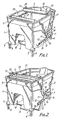
- the mopping unit illustrated in Figs. 1 and 2 comprises a moulded plastics bucket 1, typically of 24 litres capacity, combined with a wringer having two rotatable squeeze rollers 2 and 3 disposed laterally of the bucket.
- One of the rollers 2 is at a fixed lateral position at the front of the bucket 1, and the other roller 3 is movable by an operating mechanism 4 between the free "open” position shown in Fig. 1 and the "closed" operative wringing position shown in Fig. 2.
- the bucket 1 has two bail-type handles 5 (one of which is partly broken away in Fig. 2) by which it can be carried by an operative, and has four stand-off legs 6 in the form of false "gliders" at the bottom corners of the bucket.
- legs 6 maintain the bottom of the bucket 1 raised off the floor and they are fitted into corner sockets moulded into the bucket 1 at 7.
- the legs 6 will glide reasonably freely over a suitably smooth floor but castors of the same effective height can be fitted into the sockets 7, instead of the legs 6, to provide increased mobility.
- a foot-operated pedal 8 of the mechanism 4 is disposed at the bottom of a central recess 9 moulded in the front vertical face of the bucket 1 at the bottom edge thereof.
- This pedal 8 is mounted on a U-shaped pedal bar 10 with side limbs which extend along either side of the bucket 1 and which are connected via toggle linkages to two operating arms 11 respectively connected to the two ends of the movable rear roller 3.
- the linkages are duplicated at the two sides of the bucket 1, and the right hand side which is shown in the drawings will now be described.
- a mounting bracket 12 is attached to the side of the bucket 1 along the bottom edge thereof and supports a mounting pivot 13 for the corresponding side limb of the pedal bar 10.
- the corresponding operating arm 11 is pivotally mounted on the bracket 12 at 14, rearwardly of the pivot 13, and a toggle of the operating linkage comprises an end portion 15 of the pedal bar 10 and a pivotal link 16. At its ends the link 16 is respectively pivoted to the end of the portion 15 and to the arm 11.
- the bucket 1 has a flat vertical front side in which the recess 9 is formed, and the pedal 8 is positioned directly below the gap between the rollers 2 and 3 when in the closed position of Fig. 2.
- a foot can be placed on the pedal 8 to apply a downward force which directly opposes the upward pull on the mop as the latter is drawn upwardly whilst being wrung out.
- each end of the roller 3 and the corresponding arm 11 allows adjustment of the predetermined roller gap when in the closed position of Fig. 2.
- the roller is pivoted at the front end of a lever 18 which has a pivotal attachment to the corresponding arm 11.
- a thumbscrew 19 threaded into the arm 11 engages the lever 18 rearwardly of its pivotal attachment to provide means for adjusting the position of the axis of the roller 3 relative to the upper end of the arm 11.
- the bucket 1 is moulded with an upper edge recess 20.
- the front roller 2 is positioned within this recess 20 so that it does not substantially obstruct the top opening of the liquid-containing portion of the bucket 1, and the side portions provide ledges 21 over which the ends of the rollers 2 and 3 project.
- These ledges keep the strands of an inserted mop away from the ends of the rollers and, in particular, prevent them becoming entangled with the operating mechanism. It is thus not necessary to provide separately fitted "sleekers", as in prior units, to ensure that the ends of the mop strands are not left outside the ends of the rollers.
- the depth of the recess 20 is slightly greater than the common diameter of the rollers 2 and 3, so that the latter are disposed below the rim of the bucket 1 in order to prevent splashing.
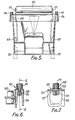
- the second embodiment illustrated in Figs. 3 to 7 is basically of similar construction to that already described, corresponding parts are denoted by the same reference numerals increased by 100. The essential differences between the two embodiments will now be fully described.
- a movable rear roller 103 is pivotally mounted directly to the two operating arms 111, and a front fixed roller 102 is pivotally connected at each end to a bucket 101 about a fixed lateral axis defined by adjustable pivot mountings 122.
- the mountings 122 are each adjustably positioned along a respective slot 123 in a hollow rim section 124 of the bucket 101, and each comprise a thumbscrew 119, a nut 125 and a stirrup 126 on which the roller 102 is pivotally mounted.
- a region 127 is provided, on the underside of the rim section 124 around each slot 123, which is serrated for engagement by the similarly serrated top surface of the respective nut 125.
- an operating mechanism 104 has operating arms 111 each of which extends through a respective slot 128 positioned in inwardly projecting portions 129 of side ledges 121.
- Pedal-operated levers 110 are pivotally mounted to brackets 112 fixed to the bucket 101
- a stirrup foot pedal 108 is pivotally mounted to one end of each of the levers 110 at pivots 130.
- Return springs 131 are attached at upper ends thereof to pegs 132 on the respective lever 110 and, at lower ends thereof, to notches 133 in the respective bracket 112.
- a stop 134 is attached to each pivotal link 116 to limit the movement of the mechanism 104 at the over-centre toggle position defining the operative forward position of the rear roller 103.
- the sockets 107 positioned at the bottom corners of the bucket 101, each receive a castor 135 providing a floor support member.
- the second embodiment operates in substantially the same manner as the first. However it is the front roller 102 which is now adjustable and the springs 131 act to return the rear roller 103 to the inoperative resting position. On depressing the foot pedal 108 the roller 103 is moved to the operative position adjacent the roller 102 and at a predetermined spacing therefrom with the pivotal links 116 going over-centre with respect to the associated levers 110, the movement over-centre being limited by the stops 134. On releasing the foot pedal 108 the springs 131 act to return the pivotal links 116 back over-centre to the rest position, but for this to occur the roller 103 must first move closer to the roller 102 as the links 116 pass back over-centre.
- Said adjustable predetermined spacing of the rollers 102 and 103 determine the squeeze pressure for a given thickness of mop, due to the use of the toggle mechanism 104, this pressure not being affected by the foot pressure which is applied to hold the bucket down as the mop is pulled through the rollers.
- the top of the recess 109 is defined by a sloping portion 136 of the bottom of the bucket 101. Dirt and other particles collected by the mop and removed during wringing out of the latter fall down the sloping portion 136 and collect in a rear sump portion 137 of the bucket 101.
- a removable grill or plate 138 is positioned over the sump portion 137 to prevent the mop picking up the dirt that has collected in the sump portion 137.
Landscapes
- Engineering & Computer Science (AREA)
- Health & Medical Sciences (AREA)
- Life Sciences & Earth Sciences (AREA)
- Molecular Biology (AREA)
- Mechanical Engineering (AREA)
- General Engineering & Computer Science (AREA)
- Cleaning Implements For Floors, Carpets, Furniture, Walls, And The Like (AREA)
- Footwear And Its Accessory, Manufacturing Method And Apparatuses (AREA)
- Containers And Packaging Bodies Having A Special Means To Remove Contents (AREA)
- Toys (AREA)
- Massaging Devices (AREA)
Claims (11)
Priority Applications (1)
| Application Number | Priority Date | Filing Date | Title |
|---|---|---|---|
| AT86304235T ATE51507T1 (de) | 1985-06-06 | 1986-06-04 | Wischlappeneinheit. |
Applications Claiming Priority (2)
| Application Number | Priority Date | Filing Date | Title |
|---|---|---|---|
| GB8514271 | 1985-06-06 | ||
| GB858514271A GB8514271D0 (en) | 1985-06-06 | 1985-06-06 | Mopping unit |
Publications (2)
| Publication Number | Publication Date |
|---|---|
| EP0207641A1 EP0207641A1 (de) | 1987-01-07 |
| EP0207641B1 true EP0207641B1 (de) | 1990-04-04 |
Family
ID=10580264
Family Applications (1)
| Application Number | Title | Priority Date | Filing Date |
|---|---|---|---|
| EP86304235A Expired - Lifetime EP0207641B1 (de) | 1985-06-06 | 1986-06-04 | Wischlappeneinheit |
Country Status (5)
| Country | Link |
|---|---|
| US (1) | US4716619A (de) |
| EP (1) | EP0207641B1 (de) |
| AT (1) | ATE51507T1 (de) |
| DE (1) | DE3669991D1 (de) |
| GB (2) | GB8514271D0 (de) |
Cited By (1)
| Publication number | Priority date | Publication date | Assignee | Title |
|---|---|---|---|---|
| DE10235304A1 (de) * | 2002-08-01 | 2004-02-12 | Carl Freudenberg Kg | Feuchtboden-Wischgerät |
Families Citing this family (43)
| Publication number | Priority date | Publication date | Assignee | Title |
|---|---|---|---|---|
| US4908904A (en) * | 1987-11-03 | 1990-03-20 | Smith Jr Don A | Portable cleaning container |
| US4815160A (en) * | 1987-11-03 | 1989-03-28 | Smith Jr Don A | Portable cleaning container |
| GB8814549D0 (en) * | 1988-06-18 | 1988-07-27 | Scot Young Serv Syst Ltd | Mopping unit |
| US5333353A (en) * | 1990-02-13 | 1994-08-02 | Scot Young Research Limited | Mop wringers and buckets |
| CN2061823U (zh) * | 1990-02-24 | 1990-09-12 | 张长荣 | 新型拖把桶 |
| DE4023219A1 (de) * | 1990-07-21 | 1992-01-23 | Dieter Sacks | Auspressgeraet fuer reinigungstuecher u. dgl. |
| RU2135068C1 (ru) * | 1995-03-24 | 1999-08-27 | Бритвин Ливерий Николаевич | Устройство для мытья полов помещений "белоручка" |
| US5615447A (en) * | 1995-04-24 | 1997-04-01 | Rubbermaid Commercial Products Inc. | Portable cleaning container having foot activated drain |
| GB2304543A (en) * | 1995-09-01 | 1997-03-26 | Peter Mckay | Mop bucket with pedestal platform |
| USD374321S (en) | 1995-09-29 | 1996-10-01 | Rubbermaid Commercial Products Inc. | Mop bucket |
| USD395531S (en) | 1997-01-27 | 1998-06-23 | Rubbermaid Commerical Products Inc. | Mop bucket |
| USD395530S (en) | 1997-01-27 | 1998-06-23 | Rubbermaid Commercial Products Inc. | Mop bucket sidewall |
| USD408602S (en) * | 1998-02-13 | 1999-04-20 | The Decor Corporation Pty Ltd | Mop bucket |
| DE19827865C2 (de) * | 1998-06-23 | 2001-06-21 | Gernot Hirse | Moppresse |
| US6115877A (en) * | 1999-04-07 | 2000-09-12 | Worldwide Integrated Resources, Inc. | Mop holding apparatus for holding a free end of a mop from turning when the mop is being wrung |
| USD429862S (en) * | 1999-10-06 | 2000-08-22 | Contico International, Inc. | Mop bucket side wall |
| US6487749B1 (en) * | 2000-06-09 | 2002-12-03 | East Trillion Co., Ltd. | Pail for squeezing water from a mop |
| GB2367835A (en) * | 2000-10-10 | 2002-04-17 | Herbert Ernest Green | Chamois wringer |
| US7270251B1 (en) * | 2001-03-06 | 2007-09-18 | Kaivac, Inc. | Multi-purpose liquid applicator |
| CA2537277C (en) * | 2003-09-30 | 2012-01-03 | Levi Deaton | Fresh dispense cleaning system |
| AU2003304583A1 (en) * | 2003-11-27 | 2005-06-24 | Francisco Barba Perez | Mop wringer pail |
| US7377004B2 (en) | 2004-04-16 | 2008-05-27 | Micronova Manufacturing, Inc. | Wringer |
| CA2565719A1 (en) * | 2004-05-05 | 2005-11-17 | Rubbermaid Commercial Products Llc | Wringer with foot pedal mechanism for flat mop pads |
| US20050262656A1 (en) * | 2004-05-05 | 2005-12-01 | Rubbermaid Commercial Products Llc | Bucket with foot pedal wringer mechanism and scrub board |
| WO2005107565A1 (en) * | 2004-05-05 | 2005-11-17 | Rubbermaid Commercial Products Llc | Color coded mop pads and method of color coding same |
| USD533356S1 (en) | 2005-01-31 | 2006-12-12 | Rubbermaid Commercial Products Llc | Universal joint |
| USD529294S1 (en) | 2005-01-31 | 2006-10-03 | Rubbermaid Commercial Products Llc | Universal joint |
| USD549414S1 (en) | 2005-01-31 | 2007-08-21 | Rubbermaid Commercial Products Llc | Mop frame |
| USD547017S1 (en) | 2005-05-10 | 2007-07-17 | Rubbermaid Commercial Products Llc | Mop handle |
| USD548913S1 (en) | 2005-05-10 | 2007-08-14 | Rubbermaid Commercial Products Llc | Mop bucket and wringer |
| USD528729S1 (en) | 2005-05-10 | 2006-09-19 | Rubbermaid Commerical Products Llc | Cart |
| USD549912S1 (en) | 2007-01-12 | 2007-08-28 | Rubbermaid Commercial Products Llc | Mop |
| US20090019654A1 (en) * | 2007-07-18 | 2009-01-22 | Debra Lingren | Compact servicing equipment and carrier combination |
| US20090265871A1 (en) * | 2008-04-24 | 2009-10-29 | Alvin Wooten | Floor cleaning system |
| USD611215S1 (en) * | 2009-01-08 | 2010-03-02 | Shop-Vac | Mop bucket |
| US8381351B2 (en) * | 2009-01-08 | 2013-02-26 | Shop-Vac | Mop bucket |
| USD619318S1 (en) * | 2009-01-08 | 2010-07-06 | Shop-Vac | Mop bucket |
| USD616168S1 (en) | 2009-08-05 | 2010-05-18 | The Libman Company | Bucket |
| USD633675S1 (en) | 2010-04-23 | 2011-03-01 | The Libman Company | Bucket |
| USD643982S1 (en) | 2011-01-12 | 2011-08-23 | The Libman Company | Wringer |
| US9936849B2 (en) * | 2014-01-06 | 2018-04-10 | Louis Paul Podraza | Janitorial bucket and wringer apparatus |
| USD756582S1 (en) | 2014-11-11 | 2016-05-17 | The Libman Company | Mop bucket |
| CN114788667B (zh) * | 2022-04-28 | 2024-05-14 | 深圳市无限动力发展有限公司 | 拖布自动净化装置和拖地机 |
Family Cites Families (6)
| Publication number | Priority date | Publication date | Assignee | Title |
|---|---|---|---|---|
| GB218837A (en) * | 1923-07-06 | 1924-07-17 | Arthur Strong | Improvements in and relating to mop-wringing attachments for buckets |
| US1679980A (en) * | 1924-03-10 | 1928-08-07 | S C Lawlor Company | Mop wringer |
| US2091625A (en) * | 1934-11-19 | 1937-08-31 | Donald E Willard | Mop wringer |
| US3506997A (en) * | 1968-06-21 | 1970-04-21 | Mfg Rodex Sa | Bucket device and wringer |
| GB1470954A (en) * | 1973-03-02 | 1977-04-21 | Straight Jane Mops Ltd | Bucket incorporating a mop wringer attachment |
| GB1501316A (en) * | 1976-10-15 | 1978-02-15 | Straight Jane Mops Ltd | Bucket incorporating a mop-wringer attachment |
-
1985
- 1985-06-06 GB GB858514271A patent/GB8514271D0/en active Pending
-
1986
- 1986-06-02 US US06/869,572 patent/US4716619A/en not_active Expired - Fee Related
- 1986-06-04 AT AT86304235T patent/ATE51507T1/de not_active IP Right Cessation
- 1986-06-04 DE DE8686304235T patent/DE3669991D1/de not_active Expired - Lifetime
- 1986-06-04 GB GB08613586A patent/GB2176094B/en not_active Expired
- 1986-06-04 EP EP86304235A patent/EP0207641B1/de not_active Expired - Lifetime
Cited By (1)
| Publication number | Priority date | Publication date | Assignee | Title |
|---|---|---|---|---|
| DE10235304A1 (de) * | 2002-08-01 | 2004-02-12 | Carl Freudenberg Kg | Feuchtboden-Wischgerät |
Also Published As
| Publication number | Publication date |
|---|---|
| EP0207641A1 (de) | 1987-01-07 |
| GB2176094B (en) | 1988-07-27 |
| GB8514271D0 (en) | 1985-07-10 |
| DE3669991D1 (de) | 1990-05-10 |
| US4716619A (en) | 1988-01-05 |
| ATE51507T1 (de) | 1990-04-15 |
| GB8613586D0 (en) | 1986-07-09 |
| GB2176094A (en) | 1986-12-17 |
Similar Documents
| Publication | Publication Date | Title |
|---|---|---|
| EP0207641B1 (de) | Wischlappeneinheit | |
| US6671923B2 (en) | Mop wringer | |
| US6128803A (en) | Container assembly | |
| US6279195B1 (en) | Ergonomic mop bucket method and apparatus | |
| US6115877A (en) | Mop holding apparatus for holding a free end of a mop from turning when the mop is being wrung | |
| US4083075A (en) | Lint pickup device | |
| EP1185191B1 (de) | Moppresse | |
| US6941612B1 (en) | Mop wringer | |
| US3921247A (en) | Mop wringer attachment for a bucket | |
| US6487749B1 (en) | Pail for squeezing water from a mop | |
| US4905339A (en) | Mopping unit | |
| US6470503B1 (en) | Foot operated device for lifting a seat of a toilet | |
| US2577496A (en) | Mopping apparatus | |
| CA2703657C (en) | Squeeze mop | |
| CA2592907C (en) | Mop bucket | |
| CA1287457C (en) | Mopping unit | |
| AU2009259123B2 (en) | Combination of wringing mechanism and container | |
| US4455466A (en) | Switch actuating mechanism | |
| AU583069B2 (en) | Improvements in buckets | |
| US2296913A (en) | Flatiron support mechanism | |
| JPS63154147A (ja) | モツプ用装置 | |
| US2794998A (en) | Combined mop and wringer | |
| JPS6036215Y2 (ja) | モツプ絞り器 | |
| US2861284A (en) | Longitudinal shoe holder or stretcher with mounting means | |
| US2384907A (en) | Mop wringer |
Legal Events
| Date | Code | Title | Description |
|---|---|---|---|
| PUAI | Public reference made under article 153(3) epc to a published international application that has entered the european phase |
Free format text: ORIGINAL CODE: 0009012 |
|
| AK | Designated contracting states |
Kind code of ref document: A1 Designated state(s): AT BE CH DE FR IT LI LU NL SE |
|
| 17P | Request for examination filed |
Effective date: 19861231 |
|
| 17Q | First examination report despatched |
Effective date: 19880909 |
|
| GRAA | (expected) grant |
Free format text: ORIGINAL CODE: 0009210 |
|
| AK | Designated contracting states |
Kind code of ref document: B1 Designated state(s): AT BE CH DE FR IT LI LU NL SE |
|
| REF | Corresponds to: |
Ref document number: 51507 Country of ref document: AT Date of ref document: 19900415 Kind code of ref document: T |
|
| ITF | It: translation for a ep patent filed | ||
| RAP2 | Party data changed (patent owner data changed or rights of a patent transferred) |
Owner name: BRUTE LIMITED |
|
| REF | Corresponds to: |
Ref document number: 3669991 Country of ref document: DE Date of ref document: 19900510 |
|
| ET | Fr: translation filed | ||
| NLT2 | Nl: modifications (of names), taken from the european patent patent bulletin |
Owner name: BRUTE LIMITED TE LYE, GROOT-BRITTANNIE. |
|
| BECN | Be: change of holder's name |
Effective date: 19900404 |
|
| RAP2 | Party data changed (patent owner data changed or rights of a patent transferred) |
Owner name: SCOT YOUNG RESEARCH LIMITED |
|
| PLBE | No opposition filed within time limit |
Free format text: ORIGINAL CODE: 0009261 |
|
| STAA | Information on the status of an ep patent application or granted ep patent |
Free format text: STATUS: NO OPPOSITION FILED WITHIN TIME LIMIT |
|
| REG | Reference to a national code |
Ref country code: CH Ref legal event code: PFA Free format text: SCOT YOUNG RESEARCH LIMITED |
|
| NLT2 | Nl: modifications (of names), taken from the european patent patent bulletin |
Owner name: SCOT YOUNG RESEARCH LIMITED TE LYE, GROOT-BRITTANN |
|
| 26N | No opposition filed | ||
| REG | Reference to a national code |
Ref country code: FR Ref legal event code: CD |
|
| PGFP | Annual fee paid to national office [announced via postgrant information from national office to epo] |
Ref country code: AT Payment date: 19930616 Year of fee payment: 8 |
|
| PGFP | Annual fee paid to national office [announced via postgrant information from national office to epo] |
Ref country code: CH Payment date: 19930628 Year of fee payment: 8 |
|
| ITTA | It: last paid annual fee | ||
| PGFP | Annual fee paid to national office [announced via postgrant information from national office to epo] |
Ref country code: LU Payment date: 19930630 Year of fee payment: 8 |
|
| EPTA | Lu: last paid annual fee | ||
| PG25 | Lapsed in a contracting state [announced via postgrant information from national office to epo] |
Ref country code: LU Free format text: LAPSE BECAUSE OF NON-PAYMENT OF DUE FEES Effective date: 19940604 Ref country code: AT Effective date: 19940604 |
|
| PG25 | Lapsed in a contracting state [announced via postgrant information from national office to epo] |
Ref country code: LI Effective date: 19940630 Ref country code: CH Effective date: 19940630 |
|
| EAL | Se: european patent in force in sweden |
Ref document number: 86304235.4 |
|
| REG | Reference to a national code |
Ref country code: CH Ref legal event code: PL |
|
| PGFP | Annual fee paid to national office [announced via postgrant information from national office to epo] |
Ref country code: FR Payment date: 19970610 Year of fee payment: 12 |
|
| PGFP | Annual fee paid to national office [announced via postgrant information from national office to epo] |
Ref country code: DE Payment date: 19970613 Year of fee payment: 12 |
|
| PGFP | Annual fee paid to national office [announced via postgrant information from national office to epo] |
Ref country code: SE Payment date: 19970618 Year of fee payment: 12 |
|
| PGFP | Annual fee paid to national office [announced via postgrant information from national office to epo] |
Ref country code: NL Payment date: 19970630 Year of fee payment: 12 |
|
| PGFP | Annual fee paid to national office [announced via postgrant information from national office to epo] |
Ref country code: BE Payment date: 19970805 Year of fee payment: 12 |
|
| PG25 | Lapsed in a contracting state [announced via postgrant information from national office to epo] |
Ref country code: SE Free format text: LAPSE BECAUSE OF NON-PAYMENT OF DUE FEES Effective date: 19980605 |
|
| PG25 | Lapsed in a contracting state [announced via postgrant information from national office to epo] |
Ref country code: DE Free format text: LAPSE BECAUSE OF NON-PAYMENT OF DUE FEES Effective date: 19980630 Ref country code: BE Free format text: LAPSE BECAUSE OF NON-PAYMENT OF DUE FEES Effective date: 19980630 |
|
| BERE | Be: lapsed |
Owner name: SCOT YOUNG RESEARCH LTD Effective date: 19980630 |
|
| PG25 | Lapsed in a contracting state [announced via postgrant information from national office to epo] |
Ref country code: NL Free format text: LAPSE BECAUSE OF NON-PAYMENT OF DUE FEES Effective date: 19990101 |
|
| PG25 | Lapsed in a contracting state [announced via postgrant information from national office to epo] |
Ref country code: FR Free format text: LAPSE BECAUSE OF NON-PAYMENT OF DUE FEES Effective date: 19990226 |
|
| EUG | Se: european patent has lapsed |
Ref document number: 86304235.4 |
|
| NLV4 | Nl: lapsed or anulled due to non-payment of the annual fee |
Effective date: 19990101 |
|
| REG | Reference to a national code |
Ref country code: FR Ref legal event code: ST |
|
| PG25 | Lapsed in a contracting state [announced via postgrant information from national office to epo] |
Ref country code: IT Free format text: LAPSE BECAUSE OF NON-PAYMENT OF DUE FEES Effective date: 20050604 |