EP0207092B1 - Vorrichtung zur zufuhr von flüssigem stahl zu einer stranggiessmaschine - Google Patents
Vorrichtung zur zufuhr von flüssigem stahl zu einer stranggiessmaschine Download PDFInfo
- Publication number
- EP0207092B1 EP0207092B1 EP19850905836 EP85905836A EP0207092B1 EP 0207092 B1 EP0207092 B1 EP 0207092B1 EP 19850905836 EP19850905836 EP 19850905836 EP 85905836 A EP85905836 A EP 85905836A EP 0207092 B1 EP0207092 B1 EP 0207092B1
- Authority
- EP
- European Patent Office
- Prior art keywords
- tundish
- bath
- electrodes
- steel
- minutes
- Prior art date
- Legal status (The legal status is an assumption and is not a legal conclusion. Google has not performed a legal analysis and makes no representation as to the accuracy of the status listed.)
- Expired
Links
- 229910000831 Steel Inorganic materials 0.000 title claims abstract description 29
- 239000010959 steel Substances 0.000 title claims abstract description 29
- 238000009749 continuous casting Methods 0.000 title claims abstract description 5
- 238000005266 casting Methods 0.000 claims description 18
- 239000007788 liquid Substances 0.000 claims description 17
- 238000010438 heat treatment Methods 0.000 claims description 11
- 238000003756 stirring Methods 0.000 claims description 7
- 239000000243 solution Substances 0.000 description 5
- 229910052799 carbon Inorganic materials 0.000 description 4
- 230000000694 effects Effects 0.000 description 4
- 238000009434 installation Methods 0.000 description 4
- OKTJSMMVPCPJKN-UHFFFAOYSA-N Carbon Chemical compound [C] OKTJSMMVPCPJKN-UHFFFAOYSA-N 0.000 description 3
- 229910002804 graphite Inorganic materials 0.000 description 3
- 239000010439 graphite Substances 0.000 description 3
- XKRFYHLGVUSROY-UHFFFAOYSA-N Argon Chemical compound [Ar] XKRFYHLGVUSROY-UHFFFAOYSA-N 0.000 description 2
- 229910001208 Crucible steel Inorganic materials 0.000 description 1
- 229910052786 argon Inorganic materials 0.000 description 1
- 238000011161 development Methods 0.000 description 1
- 230000018109 developmental process Effects 0.000 description 1
- 230000002349 favourable effect Effects 0.000 description 1
- 238000002347 injection Methods 0.000 description 1
- 239000007924 injection Substances 0.000 description 1
- 238000005272 metallurgy Methods 0.000 description 1
Images
Classifications
-
- B—PERFORMING OPERATIONS; TRANSPORTING
- B22—CASTING; POWDER METALLURGY
- B22D—CASTING OF METALS; CASTING OF OTHER SUBSTANCES BY THE SAME PROCESSES OR DEVICES
- B22D11/00—Continuous casting of metals, i.e. casting in indefinite lengths
- B22D11/10—Supplying or treating molten metal
Definitions
- the present invention relates to an improvement in the supply of liquid steel to the ingot mold or ingot molds of a continuous casting machine.
- the liquid steel is brought to the site in a pocket, coming from the converter or the electric furnace.
- the pocket has an opening at its lower part, closed by a pouring nozzle.
- the steel flows from the pocket to an intermediate tank, called a distributor, a distributor, the bottom of which is also provided with one or more orifices.
- a distributor a distributor, the bottom of which is also provided with one or more orifices.
- Each of these orifices is placed above an ingot mold, so that the liquid steel can flow from the distributor into the ingot mold (s), depending on whether the machine is single-line or multi-line.
- the casting time for a given bag is limited in time, for example to 60 to 70 minutes. Beyond this, it is considered that the drop in temperature of the steel is too great, so that pouring is no longer possible.
- This constraint of limitation in casting time often requires, for casting all of the steel contained in a given pocket, to multiply the number of casting lines, which is very disadvantageous in cost and complexity of the installation. It therefore appears that it would be very advantageous to be able to extend the casting time, at least so that the steel does not cool sufficiently before being poured into the ingot mold (s) so that the casting must be interrupted. at a certain time.
- a first solution to solve this problem would be to start casting with a very high temperature liquid steel in the ladle. Such a solution is not really conceivable because it is on the one hand bad for the quality of the cast products, and on the other hand, it greatly increases the risk of breakthroughs at the start of the casting line.
- the dispenser tank is equipped with heating means simultaneously effecting stirring of the bath by circulation of a direct current over the entire depth thereof, said means comprising at least one pair of electrodes connected respectively. at the two terminals of at least one DC electrical power source, one of the two electrodes being placed in the bottom of the distributor tank and the other at the top of it
- the direct current thus produced creates in the bath a heating and stirring effect which can be amplified by the shape of the distributor or its masonry,
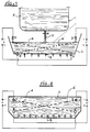
- the bag 1 is a bag of 120 tonnes of liquid steel
- the dispenser 4 is a tank of 20 tonnes of liquid steel
- the flow rate of cast steel per line is 270 kg / min.
- two graphite electrodes respectively A and B, have been installed in the top of the distributor tank 4, at each of its ends as shown and above the level 6 of the liquid steel in the tank 4, and two other graphite electrodes, respectively A 'and B', in the bottom 4, at each of its ends.
- the electrodes A, A 'and B, B' are positioned as indicated so that the lines (d, d ') which join them respectively are the as long as possible from one end of the tank to the other. In this way, the circulation of direct current can distribute its effects over most of the bath and in particular over its entire depth.
- the electrodes A and A ' are respectively connected to the negative and positive poles of a first source of direct current V, which can provide a power of up to 1.2 MVA to fix ideas, by delivering a current of up to 8000 Amperes under direct voltage up to 150 Volts.
- the electrodes B and B ' are connected respectively to the negative and positive poles of a second direct current source V', completely independent of the first source V, and with the same characteristics of power, voltage and current, as the latter .
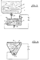
- FIGS. 3 and 4 schematically represent, and in the same way, an installation similar to that of FIGS. 1 and 2, but relating to a machine with a single casting line.
- the reference figures relating to the same objects, but suitable for casting with a single line, have therefore been used in these figures.
- the installation comprises only two graphite electrodes C and C 'and a single continuous power supply of power v.
- the electrodes C and C ' are placed respectively at the top and at the bottom (on the side in this example) of the distributor tank 4 so that the current line e which joins them in the steel bath liquid is a straight line passing right through and from top to bottom over one of the greatest possible lengths.
- the pocket 1 is a pocket initially containing 120 tonnes of liquid steel
- the distributor tank 4 has a capacity of 11 tonnes of liquid steel
- the flow rate is 1030 kg / min.
- the installed power for the continuous source v is 1200 kVA, its possibility of current goes up to 10,000 amps and its possibility of voltage goes up to 150 volts.
Landscapes
- Engineering & Computer Science (AREA)
- Mechanical Engineering (AREA)
- Continuous Casting (AREA)
Claims (4)
Applications Claiming Priority (2)
| Application Number | Priority Date | Filing Date | Title |
|---|---|---|---|
| FR8417864A FR2573682B1 (fr) | 1984-11-23 | 1984-11-23 | Dispositif d'alimentation en acier liquide d'une machine de coulee continue |
| FR8417864 | 1984-11-23 |
Publications (2)
| Publication Number | Publication Date |
|---|---|
| EP0207092A1 EP0207092A1 (de) | 1987-01-07 |
| EP0207092B1 true EP0207092B1 (de) | 1988-04-27 |
Family
ID=9309873
Family Applications (1)
| Application Number | Title | Priority Date | Filing Date |
|---|---|---|---|
| EP19850905836 Expired EP0207092B1 (de) | 1984-11-23 | 1985-11-22 | Vorrichtung zur zufuhr von flüssigem stahl zu einer stranggiessmaschine |
Country Status (5)
| Country | Link |
|---|---|
| EP (1) | EP0207092B1 (de) |
| DE (1) | DE3562321D1 (de) |
| ES (1) | ES8702191A1 (de) |
| FR (1) | FR2573682B1 (de) |
| WO (1) | WO1986003146A1 (de) |
Family Cites Families (3)
| Publication number | Priority date | Publication date | Assignee | Title |
|---|---|---|---|---|
| DE1288760B (de) * | 1966-06-14 | 1969-02-06 | Coupette | Verfahren zur Steuerung von Temperatur und Stahlanalyse beim Stranggiessen und Vorrichtung dazu |
| JPS58100951A (ja) * | 1981-12-09 | 1983-06-15 | Nippon Steel Corp | 連続鋳造用溶鋼の温度調整方法 |
| JPS58187247A (ja) * | 1982-04-28 | 1983-11-01 | Mitsubishi Heavy Ind Ltd | 金属薄板の連続鋳造方法 |
-
1984
- 1984-11-23 FR FR8417864A patent/FR2573682B1/fr not_active Expired
-
1985
- 1985-11-22 DE DE8585905836T patent/DE3562321D1/de not_active Expired
- 1985-11-22 ES ES549191A patent/ES8702191A1/es not_active Expired
- 1985-11-22 WO PCT/FR1985/000330 patent/WO1986003146A1/fr not_active Ceased
- 1985-11-22 EP EP19850905836 patent/EP0207092B1/de not_active Expired
Also Published As
| Publication number | Publication date |
|---|---|
| FR2573682B1 (fr) | 1987-02-27 |
| ES8702191A1 (es) | 1986-12-16 |
| FR2573682A1 (fr) | 1986-05-30 |
| EP0207092A1 (de) | 1987-01-07 |
| DE3562321D1 (en) | 1988-06-01 |
| WO1986003146A1 (fr) | 1986-06-05 |
| ES549191A0 (es) | 1986-12-16 |
Similar Documents
| Publication | Publication Date | Title |
|---|---|---|
| FR2602320A1 (fr) | Procede de fusion de ferraille et four electrique pour la mise en oeuvre du procede | |
| US4645534A (en) | Process for control of continuous casting conditions | |
| FR2568797A1 (fr) | Procede et appareil pour la coulee de materiaux conducteurs et semi-conducteurs | |
| EP0207092B1 (de) | Vorrichtung zur zufuhr von flüssigem stahl zu einer stranggiessmaschine | |
| CH620846A5 (de) | ||
| EP0197482A2 (de) | Vorrichtung zum Rühren des flüssigen Metalls in einer Stranggiessanlage | |
| EP0699112B1 (de) | Vorrichtung zur zufuhr einer metallschmelze, insbesondere gusseisen, bei einer giessmaschine, sowie giessmachine ausgerüstet mit dergleiche schmelzzuführung | |
| US4742611A (en) | Battery assembly process and apparatus | |
| EP0269465B1 (de) | Verfahren zum kontinuierlichen Einschmelzen von Schrott in einem Gleichstromlichtbogenofen und Gleichstromlichtbogenofen zur Durchführung des Verfahrens | |
| EP0875319B1 (de) | Zwischengefäss mit mindestens einem Plasmabrenner für die Wiederaufheizung von geschmolzenen Metallen | |
| WO2023199257A1 (fr) | Procede de fusion de metal au moyen d'un thermoplongeur electrique | |
| FR2524356A1 (fr) | Procede et dispositif pour la fabrication de poudres metalliques de haute purete et depourvues de matieres ceramiques | |
| EP0096618A1 (de) | Metallurgisches Schmelzverfahren und Elektrolichtbogenofen zur Durchführung des Verfahrens | |
| FR2767081A1 (fr) | Procede de rechauffage d'un metal liquide dans un repartiteur de coulee continue au moyen d'une torche a plasma, et repartiteur pour sa mise en oeuvre | |
| KR20000060792A (ko) | 알루미늄용탕 보온용 래들 | |
| FR2659821A1 (fr) | Four electrique a courant continu. | |
| FR2739795A1 (fr) | Appareil pour le chauffage de metal en fusion | |
| FR2480787A1 (fr) | Procede de fusion et, le cas echeant, d'affinage de la ferraille et/ou de boulettes d'acier, de fer ou d'autres metaux ou alliages et installation pour executer ce procede | |
| BE1002828A6 (fr) | Dispositif de controle de l'ecoulement du metal dans un panier repartiteur de coulee continue. | |
| JPS6348616B2 (de) | ||
| JPS6117352A (ja) | エレクトロ・スラグによる押湯加熱法 | |
| FR2545593A1 (fr) | Procede de fusion metallurgique et four a arc a courant continu pour sa mise en oeuvre | |
| JP3717103B2 (ja) | タンディッシュ内溶融金属のプラズマアーク加熱装置 | |
| FR2765818A1 (fr) | Dispositif de coulee continue | |
| FR2497618A1 (fr) | Four a induction a canal |
Legal Events
| Date | Code | Title | Description |
|---|---|---|---|
| PUAI | Public reference made under article 153(3) epc to a published international application that has entered the european phase |
Free format text: ORIGINAL CODE: 0009012 |
|
| 17P | Request for examination filed |
Effective date: 19860704 |
|
| AK | Designated contracting states |
Kind code of ref document: A1 Designated state(s): DE GB IT SE |
|
| RIN1 | Information on inventor provided before grant (corrected) |
Inventor name: DAVENE, JEAN Inventor name: PRONKIEWIEZ, JEAN |
|
| 17Q | First examination report despatched |
Effective date: 19870714 |
|
| GRAA | (expected) grant |
Free format text: ORIGINAL CODE: 0009210 |
|
| AK | Designated contracting states |
Kind code of ref document: B1 Designated state(s): DE GB IT SE |
|
| REF | Corresponds to: |
Ref document number: 3562321 Country of ref document: DE Date of ref document: 19880601 |
|
| GBT | Gb: translation of ep patent filed (gb section 77(6)(a)/1977) | ||
| ITF | It: translation for a ep patent filed | ||
| PLBE | No opposition filed within time limit |
Free format text: ORIGINAL CODE: 0009261 |
|
| STAA | Information on the status of an ep patent application or granted ep patent |
Free format text: STATUS: NO OPPOSITION FILED WITHIN TIME LIMIT |
|
| 26N | No opposition filed | ||
| PGFP | Annual fee paid to national office [announced via postgrant information from national office to epo] |
Ref country code: SE Payment date: 19911025 Year of fee payment: 7 |
|
| PGFP | Annual fee paid to national office [announced via postgrant information from national office to epo] |
Ref country code: GB Payment date: 19911108 Year of fee payment: 7 |
|
| PGFP | Annual fee paid to national office [announced via postgrant information from national office to epo] |
Ref country code: DE Payment date: 19911125 Year of fee payment: 7 |
|
| ITTA | It: last paid annual fee | ||
| PG25 | Lapsed in a contracting state [announced via postgrant information from national office to epo] |
Ref country code: GB Effective date: 19921122 |
|
| PG25 | Lapsed in a contracting state [announced via postgrant information from national office to epo] |
Ref country code: SE Effective date: 19921123 |
|
| GBPC | Gb: european patent ceased through non-payment of renewal fee |
Effective date: 19921122 |
|
| PG25 | Lapsed in a contracting state [announced via postgrant information from national office to epo] |
Ref country code: DE Effective date: 19930803 |
|
| EUG | Se: european patent has lapsed |
Ref document number: 85905836.4 Effective date: 19930610 |