EP0206759B1 - Compresseur à volutes imbriquées - Google Patents
Compresseur à volutes imbriquées Download PDFInfo
- Publication number
- EP0206759B1 EP0206759B1 EP86304704A EP86304704A EP0206759B1 EP 0206759 B1 EP0206759 B1 EP 0206759B1 EP 86304704 A EP86304704 A EP 86304704A EP 86304704 A EP86304704 A EP 86304704A EP 0206759 B1 EP0206759 B1 EP 0206759B1
- Authority
- EP
- European Patent Office
- Prior art keywords
- chamber
- end plate
- cylinder
- pressure
- intermediate pressure
- Prior art date
- Legal status (The legal status is an assumption and is not a legal conclusion. Google has not performed a legal analysis and makes no representation as to the accuracy of the status listed.)
- Expired
Links
Images


Classifications
-
- F—MECHANICAL ENGINEERING; LIGHTING; HEATING; WEAPONS; BLASTING
- F04—POSITIVE - DISPLACEMENT MACHINES FOR LIQUIDS; PUMPS FOR LIQUIDS OR ELASTIC FLUIDS
- F04C—ROTARY-PISTON, OR OSCILLATING-PISTON, POSITIVE-DISPLACEMENT MACHINES FOR LIQUIDS; ROTARY-PISTON, OR OSCILLATING-PISTON, POSITIVE-DISPLACEMENT PUMPS
- F04C18/00—Rotary-piston pumps specially adapted for elastic fluids
- F04C18/02—Rotary-piston pumps specially adapted for elastic fluids of arcuate-engagement type, i.e. with circular translatory movement of co-operating members, each member having the same number of teeth or tooth-equivalents
- F04C18/06—Rotary-piston pumps specially adapted for elastic fluids of arcuate-engagement type, i.e. with circular translatory movement of co-operating members, each member having the same number of teeth or tooth-equivalents of other than internal-axis type
-
- F—MECHANICAL ENGINEERING; LIGHTING; HEATING; WEAPONS; BLASTING
- F04—POSITIVE - DISPLACEMENT MACHINES FOR LIQUIDS; PUMPS FOR LIQUIDS OR ELASTIC FLUIDS
- F04C—ROTARY-PISTON, OR OSCILLATING-PISTON, POSITIVE-DISPLACEMENT MACHINES FOR LIQUIDS; ROTARY-PISTON, OR OSCILLATING-PISTON, POSITIVE-DISPLACEMENT PUMPS
- F04C28/00—Control of, monitoring of, or safety arrangements for, pumps or pumping installations specially adapted for elastic fluids
- F04C28/10—Control of, monitoring of, or safety arrangements for, pumps or pumping installations specially adapted for elastic fluids characterised by changing the positions of the inlet or outlet openings with respect to the working chamber
- F04C28/16—Control of, monitoring of, or safety arrangements for, pumps or pumping installations specially adapted for elastic fluids characterised by changing the positions of the inlet or outlet openings with respect to the working chamber using lift valves
Definitions
- the present invention relates to a scroll type compressor, with a variable displacement mechanism.
- the displacement of the system compressor need not necessarily be as high as under normal load. Accordingly, the compression ratio of the compressor can be decreased.
- a scroll type compressor including a housing having an inlet port and an outlet port;
- Figure 1 shows one example of a scroll type compressor in accordance with the State of the Art, and including a compressor housing 10 having a front end plate 11 and a cup-shaped casing portion 12 which is attached to an end surface of the end plate 11.
- a hole 11 is formed in the centre of the front end plate 11 for penetration of a drive shaft 13.
- An outer peripheral surface of the projection 112 extends into the peripheral wall of the cup shaped portion 12.
- An opening 121 of the portion 12 is covered by the front end plate 11.
- An 0-ring 14 is placed between the outer peripheral surface of the annular projection 112 and the inner wall surface of the portion 12 to seal the mating surfaces of the plate 11 and portion 12.
- An annular sleeve 16 projects from the front end surface of the front end plate 11 and surrounds the drive shaft 13 and defines a shaft seal cavity.
- the sleeve 16 is formed separately from the front end plate 11, and is fixed to the front end surface of the front end plate 11 by screws (not shown).
- the sleeve 15 may be formed integrally with the front end plate 11.
- the drive shaft 13 is rotatably supported by the sleeve 16 through a bearing 17 located within the front end of the sleeve 16.
- the drive shaft 13 has a disk-shaped rotor 131 at its inner end which is rotatably supported by the front end plate 11 through a bearing 15 located within the hole 111 in the front end plate 11.
- a shaft seal assembly 18 is coupled to the drive shaft 13 within the shaft seal cavity of the sleeve 16.
- a pulley 201 is rotatably supported by a ball bearing 19 which is carried on the outer surface of the sleeve 16.
- An electromagnetic coil 202 is fixed about the outer surface of the sleeve 16 by a support plate.
- An armature plate 203 is elastically supported on the outer end of the drive shaft 13.
- the pulley 201, magnetic coil 202 and armature plate 203 form a magnetic clutch 20.
- the drive shaft 13 is driven by an external power source, for example the engine of an automobile, through a rotation transmitting device, in this case the above described magnetic clutch.
- a fixed scroll 21, an orbiting scroll 22, a driving mechanism for the orbiting scroll 22 and a rotation preventing/thrust bearing mechanism 24 for the orbiting scroll 22 are disposed in the interior of the housing 10.
- the fixed scroll 21 includes a circular end plate 211 and a spiral element 212 fixed to and extending from one end surface of the circular end plate 211.
- the fixed scroll 121 is fixed within the inner chamber of the cup shaped portion 12 by screws 25 screwed into the end plate 211 from outside of the portion 12.
- the end plate 211 of the fixed scroll 21 partitions the interior of the cup shaped portion 12 into two chambers, a front chamber 27 and a rear chamber 28.
- the spiral element 212 is located within the front chamber 27.
- a partition wall 122 projects axially from the inner end surface of the cup shaped portion 12. The end surface of the partition wall 122 contacts the end surface of the circular end plate 211. Thus, the partition wall 122 divides the rear chamber 28 into a discharge chamber 281 formed at a centre portion of the rear chamber 28 and an intermediate chamber 282.
- a gasket 26 may be disposed between the end surface of the partition wall 122 and the end plate 211 to secure the sealing.
- the orbiting scroll 22 which is located in the front chamber 27, includes a spiral element 222 fixed to and extending from one end surface of the circular end plate 221.
- the spiral element 222 of the orbiting scroll 22 and the spiral element 212 of the fixed scroll 21 interfit at an angular offset of 180" and a predetermined radial offset. Sealed pockets are thus formed between the spiral elements 212 and 222.
- the orbiting scroll 22 is rotatably supported by a bushing 23, which is connected with the inner end of the disc-shaped portion 131 eccentrically to the axis the drive shaft 13, through a radial needle bearing 30.
- the rotation preventing/thrust bearing mechanism 24 includes a fixed ring 241, a fixed race 242, an orbiting ring 243, an orbiting race 244 and balls 245.
- the fixed ring 241 is attached on the inner end surface of the front end plate 11 through the fixed race 242 and has a plurality of circular holes 241 a.
- the orbiting ring 243 is attached on the rear end surface of the orbiting scroll 22 through the orbiting race 244 and has a plurality of circular holes 243a.
- Each ball 245 lies in and between a hole 241 a of the fixed ring 242 and a circular hole 243a of the orbiting ring 243, and rolls along the edges of both circular holes 241 a, 243a. Also, an axial thrust load from the orbiting scroll 22 is supported on the front end plate 11 through the balls 245.
- the compressor housing 10 is provided with an inlet port 31 and an outlet port 32 for connecting the compressor to, for example, an external refrigeration circuit.
- Refrigerant gas from the external circuit is introduced into a suction chamber 271 through the inlet port 31 and into the sealed pockets between the spiral elements 212 and 222.
- a pair of holes 214, 215 are formed in the end plate 211 of the fixed scroll 21 and are symmetrical positioned so that an axial end surface of the spiral element 222 of the orbiting scroll 22 simultaneously crosses over the holes 214, 215.
- the holes 214, 215 communicate between the sealed space and the intermediate pressure chamber 282.
- the hole 214 is at a position defined by involute angle 0 1 and opens along the inner side wall of the spiral element 212.
- the other hole 215 is placed at a position defined by involute angle (0 1 - n) and opens along the outer side wall of the spiral element 212.
- a control device such as a valve member 34 having valve plates 341, 342 is attached by fasteners 351, 352 to the end surface of the end plate 211 to oppose the holes 214, 215.
- Each valve plate 341, 342 is made of a springy material so that the inherent spring of each valve plate 341, 342 pushes it against the opening of the respective hole 214, 215 to close each hole.
- the end plate 211 of the fixed scroll 21 has also a communication hole 29 at the outer side portion of the terminal end of the spiral element 212.
- the hole 29 connects the front chamber 27 and the intermediate pressure chamber 282 via a communication chamber 283.
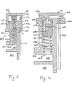
- a control mechanism 36 which controls communication between the communication chamber 283 and the intermediate pressure chamber 282, includes a cylinder 361, an I-sectioned piston 362 slidably disposed within the cylinder 361 and a coil spring 363 disposed between the lower end portion 362b of the piston 362 and the bottom of the cylinder 361 to support the piston 362.
- a first opening 361 a is formed in a side of the cylinder 362 to connected with the communication chamber 283, and a second hole 361 b is formed in a bottom of the cylinder 361 to connect with the intermediate pressure chamber 282.
- the upper portion of the cylinder 361 is covered by a plate 365 provided with an aperture 366 at its centre portion and connected with the discharge chamber 281 via a capillary tube 368.
- the communication between the cylinder 361 and the discharge chamber 281 is controlled in this case, by a magnetic valve 364 disposed on the housing 10.
- a piston ring 362c is provided on an upper portion of the piston 362 to prevent leakage of high pressure gas between the cylinder 361 and piston 362.
- Figure 3 shows an example of a control mechanism.
- the magnetic valve 364 is replaced by a bellows valve element 39, which includes a bellows portion 391 disposed in a first operating chamber 393 and a needle portion 392 attached to the bottom of the bellows portion 391.
- the first operating chamber 393 is connected to the communication chamber 283 via a connecting duct 397.
- the needle portion 392 slidably penetrates an aperture 398 and extends into a second operating chamber 394.
- the aperture 398 interconnects the first and second operating chambers 393, 394 and the second operating chamber 394 is connected to the cylinder 361 and discharge chamber 281 through the capillary tube 368.
- a ball 395 is disposed on the top end of a spring 396, which is disposed in the second operating chamber 394 and contacts the end of the needle portion 392.
- the ball 395 will control the opening and closing of the aperture 398 owing to the recoil strength of the spring 396 and the operation of the bellows portion 391.
- Figure 4 shows another example of a control mechanism which includes a cylinder 401, a piston valve 402, a bellows 403 and a spring 404.
- the piston valve 402 is slidably disposed within the cylinder and has openings 402a and 402b. Also, the piston 402 is pushed upwardly by a spring 404 disposed between the bottom portion of the cylinder 401 and the lower end surface of the piston 402.
- the bellows 403 is disposed within the interior of the piston valve 402, and includes a valve portion 403a and a bellows portion 403b.
- the valve portion 403a is extended to the outside of the piston valve 402 through opening 402a which is formed at the upper end of the piston 402.
- the cylinder 401 is connected with the discharge chamber 281 through conduits 368, 405, in which an orifice 406 is disposed.
- the valve portion 403a opens the opening 402a of the piston valve 402, and therefore, a small amount of compressed gas which is supplied to the top space of the cylinder 401 from the orifice 406 flows into the communication chamber 283 through the piston 402 and cylinder 401.
- the piston 403, which is placed to close the opening 361 b is pushed upwardly by the recoil strength of the spring 404, and accomplish communication between the communication chamber 263 and the intermediate pressure chamber 282. Therefore, the compression ratio is decreased.
- valve portion 403a is drawn down owing to operation of the bellows 403b, the opening 402a is closed by the valve portion 403a.
- a small amount of compressed gas always flows from the discharge chamber 281 into the top space of the cylinder 401, and the piston valve 402 is pushed downwardly against the recoil strength of the spring 404.
- the openings 361 (a, b), are thus closed by the piston valve 402, and the compression ratio is increased.
- a needle-ball type valve mechanism 41 may be used, as shown in Figure 5.
- the strength of the pushing force by the bellows will be controlled by positioning of the bellows 403b.
- the position of the bellows 403b will be determined by a screw 42 at the bottom of the piston valve 402, also as shown in Figure 5.
Claims (3)
Applications Claiming Priority (2)
| Application Number | Priority Date | Filing Date | Title |
|---|---|---|---|
| JP132487/85 | 1985-06-18 | ||
| JP60132487A JPH0641756B2 (ja) | 1985-06-18 | 1985-06-18 | 容量可変型のスクロール型圧縮機 |
Publications (2)
| Publication Number | Publication Date |
|---|---|
| EP0206759A1 EP0206759A1 (fr) | 1986-12-30 |
| EP0206759B1 true EP0206759B1 (fr) | 1989-05-10 |
Family
ID=15082520
Family Applications (1)
| Application Number | Title | Priority Date | Filing Date |
|---|---|---|---|
| EP86304704A Expired EP0206759B1 (fr) | 1985-06-18 | 1986-06-18 | Compresseur à volutes imbriquées |
Country Status (9)
| Country | Link |
|---|---|
| US (2) | US4744733A (fr) |
| EP (1) | EP0206759B1 (fr) |
| JP (1) | JPH0641756B2 (fr) |
| KR (1) | KR930004660B1 (fr) |
| CN (1) | CN1025449C (fr) |
| AU (1) | AU599033B2 (fr) |
| BR (1) | BR8602825A (fr) |
| DE (1) | DE3663282D1 (fr) |
| IN (1) | IN166856B (fr) |
Families Citing this family (79)
| Publication number | Priority date | Publication date | Assignee | Title |
|---|---|---|---|---|
| EP0211672B1 (fr) | 1985-08-10 | 1990-10-17 | Sanden Corporation | Compresseur à volutes imbriquées avec mécanisme de réglage du déplacement |
| JPS63212789A (ja) * | 1987-02-28 | 1988-09-05 | Sanden Corp | 可変容量型スクロ−ル圧縮機 |
| JPH0744775Y2 (ja) * | 1987-03-26 | 1995-10-11 | 三菱重工業株式会社 | 圧縮機の容量制御装置 |
| JPH0615872B2 (ja) * | 1987-06-30 | 1994-03-02 | サンデン株式会社 | 可変容量型スクロ−ル圧縮機 |
| JPH0746787Y2 (ja) * | 1987-12-08 | 1995-10-25 | サンデン株式会社 | 可変容量型スクロール圧縮機 |
| US4840545A (en) * | 1988-05-16 | 1989-06-20 | American Standard Inc. | Scroll compressor relief valve |
| JPH0219677A (ja) * | 1988-07-08 | 1990-01-23 | Sanden Corp | スクロール型流体圧縮装置 |
| JPH0245685A (ja) * | 1988-08-03 | 1990-02-15 | Daikin Ind Ltd | 横型開放圧縮機の給油機構 |
| JPH02230995A (ja) * | 1989-03-02 | 1990-09-13 | Mitsubishi Heavy Ind Ltd | ヒートポンプ用圧縮機及びその運転方法 |
| JPH0772543B2 (ja) * | 1989-08-31 | 1995-08-02 | ダイキン工業株式会社 | スクロール形圧縮機 |
| JP2780233B2 (ja) * | 1989-10-30 | 1998-07-30 | ダイキン工業株式会社 | スクロール形圧縮機 |
| JP2553033Y2 (ja) * | 1989-12-08 | 1997-11-05 | 株式会社豊田自動織機製作所 | 容量可変スクロール型圧縮機 |
| JPH0392580U (fr) * | 1990-01-11 | 1991-09-20 | ||
| JPH03116789U (fr) * | 1990-03-15 | 1991-12-03 | ||
| US5141407A (en) * | 1990-10-01 | 1992-08-25 | Copeland Corporation | Scroll machine with overheating protection |
| JP2972370B2 (ja) * | 1991-03-15 | 1999-11-08 | サンデン株式会社 | 可変容量スクロール圧縮機 |
| JP3100452B2 (ja) * | 1992-02-18 | 2000-10-16 | サンデン株式会社 | 容量可変型スクロール圧縮機 |
| US5451146A (en) * | 1992-04-01 | 1995-09-19 | Nippondenso Co., Ltd. | Scroll-type variable-capacity compressor with bypass valve |
| US5474431A (en) * | 1993-11-16 | 1995-12-12 | Copeland Corporation | Scroll machine having discharge port inserts |
| JP3376692B2 (ja) * | 1994-05-30 | 2003-02-10 | 株式会社日本自動車部品総合研究所 | スクロール型圧縮機 |
| JP3376729B2 (ja) * | 1994-06-08 | 2003-02-10 | 株式会社日本自動車部品総合研究所 | スクロール型圧縮機 |
| JPH08151991A (ja) * | 1994-11-29 | 1996-06-11 | Sanden Corp | 可変容量型スクロール圧縮機 |
| US6047557A (en) | 1995-06-07 | 2000-04-11 | Copeland Corporation | Adaptive control for a refrigeration system using pulse width modulated duty cycle scroll compressor |
| US5613841A (en) * | 1995-06-07 | 1997-03-25 | Copeland Corporation | Capacity modulated scroll machine |
| US5741120A (en) | 1995-06-07 | 1998-04-21 | Copeland Corporation | Capacity modulated scroll machine |
| JP3549631B2 (ja) * | 1995-06-26 | 2004-08-04 | サンデン株式会社 | 可変容量型スクロール圧縮機 |
| US5707210A (en) * | 1995-10-13 | 1998-01-13 | Copeland Corporation | Scroll machine with overheating protection |
| JP3723283B2 (ja) * | 1996-06-25 | 2005-12-07 | サンデン株式会社 | スクロール型可変容量圧縮機 |
| JP3585150B2 (ja) * | 1997-01-21 | 2004-11-04 | 株式会社豊田自動織機 | 可変容量圧縮機用制御弁 |
| US6206652B1 (en) | 1998-08-25 | 2001-03-27 | Copeland Corporation | Compressor capacity modulation |
| JPH11210650A (ja) | 1998-01-28 | 1999-08-03 | Sanden Corp | スクロール型圧縮機 |
| US6089830A (en) * | 1998-02-02 | 2000-07-18 | Ford Global Technologies, Inc. | Multi-stage compressor with continuous capacity control |
| US6079952A (en) * | 1998-02-02 | 2000-06-27 | Ford Global Technologies, Inc. | Continuous capacity control for a multi-stage compressor |
| US6478550B2 (en) * | 1998-06-12 | 2002-11-12 | Daikin Industries, Ltd. | Multi-stage capacity-controlled scroll compressor |
| JP2000257569A (ja) | 1999-03-04 | 2000-09-19 | Sanden Corp | スクロール圧縮機 |
| US6505475B1 (en) | 1999-08-20 | 2003-01-14 | Hudson Technologies Inc. | Method and apparatus for measuring and improving efficiency in refrigeration systems |
| JP3556898B2 (ja) * | 2000-11-16 | 2004-08-25 | 三菱重工業株式会社 | 圧縮機 |
| US6663358B2 (en) * | 2001-06-11 | 2003-12-16 | Bristol Compressors, Inc. | Compressors for providing automatic capacity modulation and heat exchanging system including the same |
| JP4070740B2 (ja) | 2004-03-31 | 2008-04-02 | 株式会社デンソー | 流体機械用の切替え弁構造 |
| US7771178B2 (en) * | 2006-12-22 | 2010-08-10 | Emerson Climate Technologies, Inc. | Vapor injection system for a scroll compressor |
| US8157538B2 (en) | 2007-07-23 | 2012-04-17 | Emerson Climate Technologies, Inc. | Capacity modulation system for compressor and method |
| JP5291317B2 (ja) * | 2007-09-28 | 2013-09-18 | 日立オートモティブシステムズ株式会社 | スクロール式流体機械及びそれを用いたエアサスペンション装置 |
| KR100916229B1 (ko) * | 2008-01-31 | 2009-09-08 | 엘지전자 주식회사 | 스크롤 압축기의 모드 전환장치 |
| CN102076963B (zh) * | 2008-05-30 | 2013-09-18 | 艾默生环境优化技术有限公司 | 一种具有容量调节系统的压缩机 |
| CN102089525B (zh) * | 2008-05-30 | 2013-08-07 | 艾默生环境优化技术有限公司 | 具有包括活塞致动的输出调节组件的压缩机 |
| US7976295B2 (en) | 2008-05-30 | 2011-07-12 | Emerson Climate Technologies, Inc. | Compressor having capacity modulation system |
| CN102149921B (zh) * | 2008-05-30 | 2014-05-14 | 艾默生环境优化技术有限公司 | 一种具有容量调节系统的压缩机 |
| CN102089524B (zh) | 2008-05-30 | 2014-09-03 | 艾默生环境优化技术有限公司 | 具有容量调节系统的压缩机 |
| US7976296B2 (en) * | 2008-12-03 | 2011-07-12 | Emerson Climate Technologies, Inc. | Scroll compressor having capacity modulation system |
| EP2391826B1 (fr) | 2009-01-27 | 2017-03-15 | Emerson Climate Technologies, Inc. | Système bipasse de démarrage et procédé pour un compresseur |
| US7988433B2 (en) | 2009-04-07 | 2011-08-02 | Emerson Climate Technologies, Inc. | Compressor having capacity modulation assembly |
| US8616014B2 (en) | 2009-05-29 | 2013-12-31 | Emerson Climate Technologies, Inc. | Compressor having capacity modulation or fluid injection systems |
| US8568118B2 (en) * | 2009-05-29 | 2013-10-29 | Emerson Climate Technologies, Inc. | Compressor having piston assembly |
| TW201120316A (en) * | 2009-12-04 | 2011-06-16 | Ind Tech Res Inst | Self-sealing scroll compressor |
| US8517703B2 (en) * | 2010-02-23 | 2013-08-27 | Emerson Climate Technologies, Inc. | Compressor including valve assembly |
| CN102865228B (zh) * | 2012-09-06 | 2015-09-30 | 安徽东升机电有限责任公司 | 热泵型电动汽车空调压缩机 |
| US9651043B2 (en) | 2012-11-15 | 2017-05-16 | Emerson Climate Technologies, Inc. | Compressor valve system and assembly |
| US9249802B2 (en) | 2012-11-15 | 2016-02-02 | Emerson Climate Technologies, Inc. | Compressor |
| US9127677B2 (en) | 2012-11-30 | 2015-09-08 | Emerson Climate Technologies, Inc. | Compressor with capacity modulation and variable volume ratio |
| US9435340B2 (en) | 2012-11-30 | 2016-09-06 | Emerson Climate Technologies, Inc. | Scroll compressor with variable volume ratio port in orbiting scroll |
| CN103233896B (zh) * | 2013-05-15 | 2015-10-28 | 力达(中国)机电有限公司 | 一种涡旋式空气压缩机 |
| JP6387613B2 (ja) * | 2014-01-08 | 2018-09-12 | 株式会社豊田自動織機 | 電動圧縮機 |
| US9739277B2 (en) | 2014-05-15 | 2017-08-22 | Emerson Climate Technologies, Inc. | Capacity-modulated scroll compressor |
| US9989057B2 (en) | 2014-06-03 | 2018-06-05 | Emerson Climate Technologies, Inc. | Variable volume ratio scroll compressor |
| KR101873417B1 (ko) * | 2014-12-16 | 2018-07-31 | 엘지전자 주식회사 | 스크롤 압축기 |
| US9790940B2 (en) | 2015-03-19 | 2017-10-17 | Emerson Climate Technologies, Inc. | Variable volume ratio compressor |
| US10378540B2 (en) | 2015-07-01 | 2019-08-13 | Emerson Climate Technologies, Inc. | Compressor with thermally-responsive modulation system |
| US10598180B2 (en) | 2015-07-01 | 2020-03-24 | Emerson Climate Technologies, Inc. | Compressor with thermally-responsive injector |
| CN207377799U (zh) | 2015-10-29 | 2018-05-18 | 艾默生环境优化技术有限公司 | 压缩机 |
| US10801495B2 (en) | 2016-09-08 | 2020-10-13 | Emerson Climate Technologies, Inc. | Oil flow through the bearings of a scroll compressor |
| US10890186B2 (en) | 2016-09-08 | 2021-01-12 | Emerson Climate Technologies, Inc. | Compressor |
| US10753352B2 (en) | 2017-02-07 | 2020-08-25 | Emerson Climate Technologies, Inc. | Compressor discharge valve assembly |
| CN107165824A (zh) * | 2017-04-26 | 2017-09-15 | 合肥江航飞机装备有限公司 | 一种车用空调涡旋变量压缩机核心控制波组件 |
| US11022119B2 (en) | 2017-10-03 | 2021-06-01 | Emerson Climate Technologies, Inc. | Variable volume ratio compressor |
| US10962008B2 (en) | 2017-12-15 | 2021-03-30 | Emerson Climate Technologies, Inc. | Variable volume ratio compressor |
| US10995753B2 (en) | 2018-05-17 | 2021-05-04 | Emerson Climate Technologies, Inc. | Compressor having capacity modulation assembly |
| US11656003B2 (en) | 2019-03-11 | 2023-05-23 | Emerson Climate Technologies, Inc. | Climate-control system having valve assembly |
| US11655813B2 (en) | 2021-07-29 | 2023-05-23 | Emerson Climate Technologies, Inc. | Compressor modulation system with multi-way valve |
| US11846287B1 (en) | 2022-08-11 | 2023-12-19 | Copeland Lp | Scroll compressor with center hub |
Family Cites Families (7)
| Publication number | Priority date | Publication date | Assignee | Title |
|---|---|---|---|---|
| US3759057A (en) * | 1972-01-10 | 1973-09-18 | Westinghouse Electric Corp | Room air conditioner having compressor with variable capacity and control therefor |
| US4459817A (en) * | 1980-12-16 | 1984-07-17 | Nippon Soken, Inc. | Rotary compressor |
| JPS57148089A (en) * | 1981-03-09 | 1982-09-13 | Sanden Corp | Scroll type compressor |
| JPS58155287A (ja) * | 1982-03-09 | 1983-09-14 | Nippon Soken Inc | 冷凍装置 |
| JPS5928083A (ja) * | 1982-08-07 | 1984-02-14 | Sanden Corp | スクロ−ル型圧縮機 |
| JPS60101295A (ja) * | 1983-11-08 | 1985-06-05 | Sanden Corp | 圧縮容量可変型のスクロ−ル型圧縮機 |
| SE457902B (sv) * | 1984-11-09 | 1989-02-06 | Sanden Corp | Fluidkompressor av spiralhjulstyp med mekanism foer instaellning av deplacementet |
-
1985
- 1985-06-18 JP JP60132487A patent/JPH0641756B2/ja not_active Expired - Fee Related
-
1986
- 1986-06-18 CN CN86105602A patent/CN1025449C/zh not_active Expired - Lifetime
- 1986-06-18 AU AU58830/86A patent/AU599033B2/en not_active Expired
- 1986-06-18 US US06/875,561 patent/US4744733A/en not_active Ceased
- 1986-06-18 BR BR8602825A patent/BR8602825A/pt not_active IP Right Cessation
- 1986-06-18 DE DE8686304704T patent/DE3663282D1/de not_active Expired
- 1986-06-18 EP EP86304704A patent/EP0206759B1/fr not_active Expired
- 1986-06-18 KR KR1019860004833A patent/KR930004660B1/ko not_active IP Right Cessation
- 1986-06-30 IN IN566/DEL/86A patent/IN166856B/en unknown
-
1990
- 1990-05-10 US US07/522,058 patent/USRE34148E/en not_active Expired - Lifetime
Also Published As
| Publication number | Publication date |
|---|---|
| DE3663282D1 (en) | 1989-06-15 |
| USRE34148E (en) | 1992-12-22 |
| BR8602825A (pt) | 1987-02-10 |
| KR870000508A (ko) | 1987-02-18 |
| EP0206759A1 (fr) | 1986-12-30 |
| JPH0641756B2 (ja) | 1994-06-01 |
| CN1025449C (zh) | 1994-07-13 |
| IN166856B (fr) | 1990-07-28 |
| CN86105602A (zh) | 1987-04-01 |
| US4744733A (en) | 1988-05-17 |
| AU599033B2 (en) | 1990-07-12 |
| KR930004660B1 (ko) | 1993-06-02 |
| JPS61291792A (ja) | 1986-12-22 |
| AU5883086A (en) | 1986-12-24 |
Similar Documents
| Publication | Publication Date | Title |
|---|---|---|
| EP0206759B1 (fr) | Compresseur à volutes imbriquées | |
| EP0373269B1 (fr) | Compresseurs à volutes imbriquées avec mécanisme de variation de déplacement | |
| EP0211672B1 (fr) | Compresseur à volutes imbriquées avec mécanisme de réglage du déplacement | |
| US4642034A (en) | Scroll type compressor with displacement adjusting mechanism | |
| US4505651A (en) | Scroll type compressor with displacement adjusting mechanism | |
| EP0297840B1 (fr) | Compresseurs à volutes imbriquées avec mécanisme de variation de déplacement | |
| US4673340A (en) | Variable capacity scroll type fluid compressor | |
| US4468178A (en) | Scroll type compressor with displacement adjusting mechanism | |
| EP0009350B1 (fr) | Compresseurs du type à spirale | |
| EP0043701B1 (fr) | Contrôle de capacité pour un appareil de déplacement de fluide à volutes imbriquées | |
| US4514150A (en) | Scroll type compressor with displacement adjusting mechanism | |
| US4890987A (en) | Scroll type compressor with seal supporting anti-wear plate portions | |
| EP0503629B1 (fr) | Compresseurs à volutes imbriquées avec mécanisme de variation de déplacement | |
| EP0754862B1 (fr) | Appareil de déplacement de fluide avec dispositif de variation du déplacement | |
| EP0113786A1 (fr) | Compresseur à volutes imbriquées avec mécanimsme de contrôle du débit | |
| GB2146075A (en) | Scroll type compressor with displacement adjusting mechanism | |
| EP0468238B1 (fr) | Compresseur à spirales avec mécanisme de déplacement variable | |
| JPH0255636B2 (fr) |
Legal Events
| Date | Code | Title | Description |
|---|---|---|---|
| PUAI | Public reference made under article 153(3) epc to a published international application that has entered the european phase |
Free format text: ORIGINAL CODE: 0009012 |
|
| AK | Designated contracting states |
Kind code of ref document: A1 Designated state(s): DE FR GB IT SE |
|
| 17P | Request for examination filed |
Effective date: 19870320 |
|
| 17Q | First examination report despatched |
Effective date: 19880606 |
|
| GRAA | (expected) grant |
Free format text: ORIGINAL CODE: 0009210 |
|
| AK | Designated contracting states |
Kind code of ref document: B1 Designated state(s): DE FR GB IT SE |
|
| ITF | It: translation for a ep patent filed |
Owner name: JACOBACCI & PERANI S.P.A. |
|
| REF | Corresponds to: |
Ref document number: 3663282 Country of ref document: DE Date of ref document: 19890615 |
|
| ET | Fr: translation filed | ||
| PLBE | No opposition filed within time limit |
Free format text: ORIGINAL CODE: 0009261 |
|
| STAA | Information on the status of an ep patent application or granted ep patent |
Free format text: STATUS: NO OPPOSITION FILED WITHIN TIME LIMIT |
|
| 26N | No opposition filed | ||
| ITTA | It: last paid annual fee | ||
| EAL | Se: european patent in force in sweden |
Ref document number: 86304704.9 |
|
| REG | Reference to a national code |
Ref country code: GB Ref legal event code: IF02 |
|
| PGFP | Annual fee paid to national office [announced via postgrant information from national office to epo] |
Ref country code: SE Payment date: 20050607 Year of fee payment: 20 |
|
| PGFP | Annual fee paid to national office [announced via postgrant information from national office to epo] |
Ref country code: FR Payment date: 20050608 Year of fee payment: 20 |
|
| PGFP | Annual fee paid to national office [announced via postgrant information from national office to epo] |
Ref country code: GB Payment date: 20050615 Year of fee payment: 20 |
|
| PGFP | Annual fee paid to national office [announced via postgrant information from national office to epo] |
Ref country code: DE Payment date: 20050616 Year of fee payment: 20 |
|
| PGFP | Annual fee paid to national office [announced via postgrant information from national office to epo] |
Ref country code: IT Payment date: 20050627 Year of fee payment: 20 |
|
| REG | Reference to a national code |
Ref country code: GB Ref legal event code: PE20 |
|
| PG25 | Lapsed in a contracting state [announced via postgrant information from national office to epo] |
Ref country code: GB Free format text: LAPSE BECAUSE OF EXPIRATION OF PROTECTION Effective date: 20060617 |
|
| EUG | Se: european patent has lapsed |