EP0206199A2 - Système de détection de la phase de la salve de synchronisation de couleurs pour l'usage dans un système de reproduction à disque vidéo - Google Patents
Système de détection de la phase de la salve de synchronisation de couleurs pour l'usage dans un système de reproduction à disque vidéo Download PDFInfo
- Publication number
- EP0206199A2 EP0206199A2 EP86108188A EP86108188A EP0206199A2 EP 0206199 A2 EP0206199 A2 EP 0206199A2 EP 86108188 A EP86108188 A EP 86108188A EP 86108188 A EP86108188 A EP 86108188A EP 0206199 A2 EP0206199 A2 EP 0206199A2
- Authority
- EP
- European Patent Office
- Prior art keywords
- signal
- phase
- burst
- differentiation
- generating
- Prior art date
- Legal status (The legal status is an assumption and is not a legal conclusion. Google has not performed a legal analysis and makes no representation as to the accuracy of the status listed.)
- Granted
Links
Images

Classifications
-
- H—ELECTRICITY
- H04—ELECTRIC COMMUNICATION TECHNIQUE
- H04N—PICTORIAL COMMUNICATION, e.g. TELEVISION
- H04N9/00—Details of colour television systems
- H04N9/79—Processing of colour television signals in connection with recording
- H04N9/87—Regeneration of colour television signals
- H04N9/873—Regeneration of colour television signals for restoring the colour component sequence of the reproduced chrominance signal
-
- Y—GENERAL TAGGING OF NEW TECHNOLOGICAL DEVELOPMENTS; GENERAL TAGGING OF CROSS-SECTIONAL TECHNOLOGIES SPANNING OVER SEVERAL SECTIONS OF THE IPC; TECHNICAL SUBJECTS COVERED BY FORMER USPC CROSS-REFERENCE ART COLLECTIONS [XRACs] AND DIGESTS
- Y10—TECHNICAL SUBJECTS COVERED BY FORMER USPC
- Y10S—TECHNICAL SUBJECTS COVERED BY FORMER USPC CROSS-REFERENCE ART COLLECTIONS [XRACs] AND DIGESTS
- Y10S348/00—Television
- Y10S348/905—Reproduction of a color field or frame
Definitions
- the present invention relates to a phase detection system, and more particularly, to a system for detecting the phase of a color burst signal component of a video signal, which is suited for use in a video disk player system.
- CAV Constant Angular Velocity
- This equation represents that subcarrier signals recorded in a first frame and an adjacent second frame are 180° out of phase.
- the phase difference between the subcarrier signals recorded in two adjacent recording track sections is equal to 180°.
- the continuity of the phase alternation codition of the subcarrier signal is maintained during a normal playback mode in which the recorded video format signal is picked up from an innermost part of the recording track to an outermost portion thereof.
- video disk playback systems are generally constructed to perform the so called SCAN playback mode for performing a fast speed playback operation in which an information reading point of a pickup device is moved in a radial direction across a plurality of the recording track portions.
- a tracking servo system of the playback system which has a tracking actuator is actuated to place the information reading point of the pickup device at each of the recording track portions on the recording disk in sequence, during the radial movement of the pickup device.
- the movement of the tracking actuator is limited within a predetermined movable range, it is necessary to stop the tracing operation of the tracking servo system so as to put the position of the tracking actuator back to a center of the movable range.
- the light beam for reading information moves across a plurality of recording track portions.
- the phase relation between the color subcarrier signals of the video signals picked up before and after the crossing of the recording track portions by the pickup means will be discussed. If the number of circular track portions across which the information reading point moves is even, there will be no phase difference between the color subcarrier signals, and the continuity of the video format signal is maintained. On the other hand, if the number of track portions across which the information reading point moves is odd, the phase difference between the color subcarrier signals before and after the movement of the information reading point becomes equal to 180°. Therefore, the continuity of the video format signal is not maintained under this condition. If a playback video signal under this condition is monitored by a video monitor system, the proper hue of the video information is not reproduced when the phase of the color subcarrier signal is inverted. Thus, the reproduction of the color component of the video information becomes unstable.
- the present invention is made to avoid the above mentioned problem, and an object of the present invention is therefore to provide a burst phase detection system which is able to positively detect whether the burst phase is inverted or not, using a relatively simple circuit construction and without being affected by the noises or the like.
- Another object of the present invention is to provide a burst phase detection system suited for use in a video information playback system having a frame memory.
- a burst phase detection system for a video disk player system is constructed such that a phase comparison is performed between the color burst signal in the video format signal and a reference color subcarrier signal, and the occurence of an inversion of phase of the color burst signal is detected when magnitude of the change in the comparator output signal exceeds a predetermined reference level.
- a pair of phase comparators having different axes of phase detection are provided as means for phase comparing the color burst signal and the color subcarrier signal.
- a level change exceeding a predetermined reference level occurs in either one or both of output signals of these phase comparators, such a condition is detected as an indication of the inversion of the burst phase of the video signal.
- the video singal reproduction system includes a video demodulator 1 which receives a playback RF (Radio Frequency) signal and demodulates the same to a video signal.
- the video signal obtained at the demodulator circuit 1 is then applied to a switching circuit 3 and a chroma phase invertor 2 whose output is connected to a terminal of the switching circuit 3.
- a switching circuit 3 At the switching circuit 3, one of the video signals from the demodulator circuit 1 and the chroma phase invertor 2 is selected as an output video signal and in turn supplied to an outside circuit.
- the detection system includes a reference pulse signal oscillator 4 whose oscillation frequency (7.16MHz) is twice the frequency (3.58MHz) of the subcarrier signal.
- a reference pulse signal generated by this reference pulse signal oscillator 4 is divided at a dividing circuit 5 by a dividing factor of 1/455, to form a reference horizontal synchronization signal f H which is applied to a phase comparator 6.
- the reference horizontal synchronization signal f is compared with a playback horizontal synchronization signal which is extracted at a horizontal synchronization signal separating circuit 7.
- a comparator output signal generated at the phase comparator 6 is supplied to a spindle motor 10 and a time base controller 11 through equalizer amplifiers 8 and 9 respectively.
- the time base controller 11 for example, consisits of a tangential mirror or a delay line made up of the CCD (charge coupled device).
- a time base servo loop is constructed. In this time base servo loop, the contol operation is effected so that the reference horizontal synchronization signal and the horizontal synchronization signal in the playback signal are coincide in phase with each other.
- Output pulse signal of the reference pulse signal oscillator 4 is divided by 2 at a divider 12 to form a reference subcarrier signal fsc of 3.58MHz.
- This reference subcarrier signal fsc is phase compared, at a phase comparator 13, with a playback video signal.
- An output signal of the phase comparator 13 is supplied to a burst S/H (sample and hold) circuit 14 in which the phase difference within the burst period is detected.
- An output al of the burst S/H circuit 14 is then supplied to a differentiation circuit 15 in which the input signal is differentiated, and an output signal of the differentiation circuit 15 is supplied to an input terminal of an OR gate 17 through a window comparator 16.
- the reference subcarrier signal fsc is supplied to a 90° phase shift circuit 18 in which the input signal is phase shifted by 90°.
- An output signal of the phase shift circuit 18 is in turn supplied to a phase comparator 19 whose phase detection axis is substantially perpendicular to that of the phase comparator 13, in which the output signal of the phase shift circuit 18 is phase compared with the playback video signal.
- An output signal of the phase comparator l9 is in turn supplied to a burst S/H circuit 20 in which the phase difference within the burst period is detected. Further, an output signal of the burst phase S/H circuit 20 is differentiated at a differentiation circuit 21 and in turn supplied to the other input terminal of the OR gate 17 through a window comparator 22.
- An output signal of the OR gate 17 forms an inversion detection signal which represents the condition in which the burst phase of the video signal is inverted.
- the above explained circuit part enclosed by a partly dotted line form a detection part of the burst phase inversion detection system which is generally denoted by 30.
- An inversion detection signal generated by this detection part 30 of the burst phase inversion detection system is supplied to a flip-flop circuit 23 as a trigger signal, and an output signal of the flip-flop circuit 23 is supplied to the switch circuit 3 as a switch control signal.
- phase comparator 13 The phase comparison between the reference subcarrier signal fsc and the color burst signal is performed in the phase comparator 13 and the burst S/H circuit 14.
- a change in the level of the phase comparison signal occurs when the chroma phase is inverted after the information reading point has moved across a plurality of track portions for the scanning operation.
- This level change is detected by the differentiation circuit 15 and transformed to a pulse signal at the window comparator 16 of the next stage.
- This pulse signal is supplied, as the detection signal of the inversion of the phase alternation condition, to the flip-flop circuit 23 through the OR gate 17.
- the state of the flip-flop circuit 23 in changed in response to edges of the pulse signal.
- the switch position changes to a position n after the crossing of tracks, to select the video signal supplied directly from the demodulator 1. With this operation, even the information reading point crosses the recording tracks, the output video signal will have the subcarrier signal in continuous form.
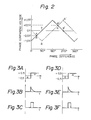
- phase comparators 13 and 19 general multiplyer type circuits can be used. Since the axes of the phase detection of the phase comparators 13 and 19 are selected to be substantially perpendicular to each other, two phase comparing characteristics as shown in Fig. 2 are obtained.
- the output signal of the phase comparator 13 is indicated by a point a in Fig. 2.
- the output signal level of the phase comparator 13 is equal to -0.5V.
- the operation of the phase comparator 13 is indicated by the point a' and the output signal level of the phase comparator 13 becomes equal to +0.5V.
- the change in the phase comparing voltage (a) from -0.5V to +0.5V is detected by the differentiation circuit 15 which provide a differentiator output signal (b).
- a waveform shaping of the differentiator output signal (b) is in turn effected in the window comparator 16 to provide a pulse signal (c).
- the detection of the inversion of the burst phase is performed.
- the operation of the circuit part including the phase comparator 19 is performed in the same manner during this period. As illustrated, in Fig. 2, the operation is expressed by a movement from a point A which is coincident with the point a to a point A' which is coincident with the point a'.
- This operation of the circuit part including the phase comparator 19 is also illustrated in Fig. 3D through 3F.
- the detection of the inversion of the phase is detected by both of the circuit part including the phase comparator 13 and the circuit part including the phase comparator 19.
- the inversion detection signal is derived at an output terminal of the OR gate 17.
- the polarity of the differentiator output signal also becomes negative when the change in phase occurs in the reverse direction, i.e. from the point a' (A') to the point a (A).
- the phase inversion of 180 0 can be detected in the same manner by means of the operation of the window comparators 16 and 22.
- phase comparator 13 is such as shown by a movement from a point b to a point b'. Therefore, if the burst phase is shifed by 180° (from 90° to 270°), there will be no change in the phase comparator voltage (a), as shown in Figs. 4A through 4C. Therefore, under this condition, it is not possible to detect the inversion of the phase by the circuit part including the phase comparator 13.
- the detection operation is attained as illustrated by the movement of from a point B to a point B' so that the phase comparison voltage (a) changes from -1.0V to +1.0V as illustrated in Fig. 4D through Fig. 4F.
- This change is then detected by the differentiation circuit 21, and a differentiation output signal (b) from the differentiation circuit 21 is treated by the window comparator 22 acting as a waveform shaping circuit so that a pulse signal (c) is produced.
- the detection of inversion of the burst phase alternation condition is also performed in this state.
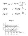
- Fig. 5 shows the level change in the output signals of the phase comparators 13 and 19 when the phase of the burst signal is inverted (or in other words, shifted by 180°).
- the solid line shows the variation of the output signal level of the phase comparator 13
- the dashed line shows the change in the output signal of the phase comparator 19. Since the window comparators 16 and 22 are constructed in the same manner, the threshold level +V T , -V are set at + 0.5V in the example of Fig. 5.
- the inversion of the phase can be detected without regard to the phase difference between the burst signal and the reference subcarrier signal fsc. Practically, it is desirable to set the threshold levels +V T and -VT at + 0.4V to leave a margin.
- a pair of phase comparators are utilized for detecting the inversion of the phase of the burst signal.
- the construction of the system is not limited to that of the described embodiment.
- a single phase comparator (for instance, only the phase comparator 13) may be used for detecting the phase inversion of the color burst signal.
- the level change is limited to a range illustated by the solid line of Fig. 5, i.e., the range of the detection of the phase inversion is narrower than that of the previous case in which a pair of phase comparators are utilized. Therefore, it is necessary to set the threshold levels +V T and -V of the window comparator 16 at small levels. However, even with small threshold levels, it is not possible to detect the inversion when the phase difference between the burst signal and the reference subcarrier signal fsc is near to 180°.
- the time base servo control is performed by a phase comparison between the reference horizontal synchronization signal fH obtained by dividing 2fsc by 455 and the playback horizontal synchronization signal. Therefore, to lock the phase difference between the subcarrier signal fsc and the color burst signal of the playback video signal at 45 0 , it is necessary to maintain the stationary error of the servo loop and the deviation of the delay time of the divider 5 less than the order of + 5nsec, for example. However, this is practically difficult.
- phase comparators 13 and 19 for detecting the inversion of the burst phase.
- the detection of the inversion of phase can be performed for the whole range of the phase difference between the burst signal and the reference subcarrier signal.
- the color burst phase detection system is utilized for maintaining the continuity of chroma signal of the playback video signal, especially from a video disk player system during a scan operation.
- the application of the invention is not limited to this.
- the system can be utilized for maintaining the continuity of chroma signal during a multi-track jump operation in the above mentioned disk player system.
- the invention is applicable as a burst phase continuity detection circuit which maintains the continuity of burst phase in a picture reproduction system which uses a frame memory system, such as described in British patent application No. 8608422 and German patent application No. P36 11 257.7 which are based on Japanese patent application number 60-73044 by the applicant of the present application.
- a switch circuit for performing the selection between a playback video signal supplied from a digital to analog converter and the same playback video signal which is supplied through a delay line.
- the operation of the switch circuit is controlled by an output signal of a burst continuity detection circuit.
- the color burst phase detection system according to the present invention can be used as the burst continuity detection circuit, to controll the operation of the switch circuit.
- the continuity of the color subcarrier signal is surely maintained by the system according to the present invention also in the picture reproduction system utilizing a frame memory.
- the color burst signal is directly used to detect the inversion of the burst phase. Therefore, the system is hardly affected by noises and the circuit construction of the system is simplified. Further, there is an advantage that the cost of the system is relatively small.
Applications Claiming Priority (2)
| Application Number | Priority Date | Filing Date | Title |
|---|---|---|---|
| JP131499/85 | 1985-06-17 | ||
| JP60131499A JPS61288693A (ja) | 1985-06-17 | 1985-06-17 | バ−スト位相反転検出装置 |
Publications (3)
| Publication Number | Publication Date |
|---|---|
| EP0206199A2 true EP0206199A2 (fr) | 1986-12-30 |
| EP0206199A3 EP0206199A3 (en) | 1989-03-08 |
| EP0206199B1 EP0206199B1 (fr) | 1993-01-13 |
Family
ID=15059437
Family Applications (1)
| Application Number | Title | Priority Date | Filing Date |
|---|---|---|---|
| EP86108188A Expired - Lifetime EP0206199B1 (fr) | 1985-06-17 | 1986-06-16 | Système de détection de la phase de la salve de synchronisation de couleurs pour l'usage dans un système de reproduction à disque vidéo |
Country Status (4)
| Country | Link |
|---|---|
| US (1) | US4734757A (fr) |
| EP (1) | EP0206199B1 (fr) |
| JP (1) | JPS61288693A (fr) |
| DE (1) | DE3687481T2 (fr) |
Families Citing this family (8)
| Publication number | Priority date | Publication date | Assignee | Title |
|---|---|---|---|---|
| US5012327A (en) * | 1988-09-09 | 1991-04-30 | Ampex Corporation | Circuit for and method of detecting a color field sequence of a color video signal |
| US4970581A (en) * | 1988-09-09 | 1990-11-13 | Ampex Corporation | Circuit for and method of detecting color field sequence in a color video signal |
| US5185657A (en) * | 1989-04-26 | 1993-02-09 | Victor Company Of Japan, Ltd. | Color signal processing circuit with residual phase error correction |
| US5130787A (en) * | 1989-04-26 | 1992-07-14 | Victor Company Of Japan, Ltd. | Color signal processing circuit with residue phase error correction |
| JPH04220094A (ja) * | 1990-12-19 | 1992-08-11 | Sony Corp | バースト位相検出回路 |
| JPH07143520A (ja) * | 1993-11-19 | 1995-06-02 | Nippon Columbia Co Ltd | 映像信号再生装置 |
| US7356186B2 (en) * | 2002-08-23 | 2008-04-08 | Kulas Charles J | Digital representation of audio waveforms using peak shifting to provide increased dynamic range |
| KR100688511B1 (ko) * | 2004-12-20 | 2007-03-02 | 삼성전자주식회사 | 영상 신호의 부반송파 추적을 위한 디지털 처리 장치 및방법 |
Citations (8)
| Publication number | Priority date | Publication date | Assignee | Title |
|---|---|---|---|---|
| US3553357A (en) * | 1967-02-02 | 1971-01-05 | Rca Corp | Switching mode control circuits |
| DE2549364A1 (de) * | 1974-11-05 | 1976-05-06 | Victor Company Of Japan | Anordnung zur wiedergabe von pal- farbbildsignalgemischen |
| US4145704A (en) * | 1977-01-28 | 1979-03-20 | Ampex Corporation | Television subcarrier phase correction for color field sequencing |
| US4251830A (en) * | 1978-04-07 | 1981-02-17 | Sony Corporation | System for removing vertical vibrations from reproduced video |
| US4258384A (en) * | 1978-11-30 | 1981-03-24 | Sony Corporation | Color video signal processing system |
| US4300155A (en) * | 1979-04-19 | 1981-11-10 | Matsushita Electric Industrial Co., Ltd. | PAL Demodulator having non-synchronized line switch |
| EP0045221A2 (fr) * | 1980-07-30 | 1982-02-03 | Matsushita Electric Industrial Co., Ltd. | Circuit démodulateur pour signaux de télévision en couleur dans le système PAL |
| FR2537815A1 (fr) * | 1982-12-14 | 1984-06-15 | Victor Company Of Japan | Dispositif de restitution de signaux de television en couleur |
Family Cites Families (6)
| Publication number | Priority date | Publication date | Assignee | Title |
|---|---|---|---|---|
| US3562413A (en) * | 1967-05-22 | 1971-02-09 | Ampex | Switching sequence detector for p.a.l. color television |
| DE2508269C3 (de) * | 1975-02-26 | 1978-10-26 | Integral Hydraulik Langen & Co, 4000 Duesseldorf | Verfahren zum gas- und flüssigkeitsdichten Verschließen von gewindelosen, unter Druck stehenden, in einem aus härtbarem Werkstoff bestehenden Bauteil angebrachten Bohrungen |
| US4024571A (en) * | 1975-08-14 | 1977-05-17 | Rca Corporation | Synchronizing system employing burst crossover detection |
| JPS5360517A (en) * | 1976-11-12 | 1978-05-31 | Hitachi Ltd | Regenerating system for color television signal |
| JPS59122299A (ja) * | 1982-12-28 | 1984-07-14 | Sony Corp | カラ−映像信号再生装置 |
| US4620219A (en) * | 1984-08-06 | 1986-10-28 | Rca Corporation | Apparatus for detecting a chrominance reference burst component to develop a burst gate pulse |
-
1985
- 1985-06-17 JP JP60131499A patent/JPS61288693A/ja active Granted
-
1986
- 1986-06-16 EP EP86108188A patent/EP0206199B1/fr not_active Expired - Lifetime
- 1986-06-16 DE DE8686108188T patent/DE3687481T2/de not_active Expired - Fee Related
- 1986-06-16 US US06/874,674 patent/US4734757A/en not_active Expired - Fee Related
Patent Citations (8)
| Publication number | Priority date | Publication date | Assignee | Title |
|---|---|---|---|---|
| US3553357A (en) * | 1967-02-02 | 1971-01-05 | Rca Corp | Switching mode control circuits |
| DE2549364A1 (de) * | 1974-11-05 | 1976-05-06 | Victor Company Of Japan | Anordnung zur wiedergabe von pal- farbbildsignalgemischen |
| US4145704A (en) * | 1977-01-28 | 1979-03-20 | Ampex Corporation | Television subcarrier phase correction for color field sequencing |
| US4251830A (en) * | 1978-04-07 | 1981-02-17 | Sony Corporation | System for removing vertical vibrations from reproduced video |
| US4258384A (en) * | 1978-11-30 | 1981-03-24 | Sony Corporation | Color video signal processing system |
| US4300155A (en) * | 1979-04-19 | 1981-11-10 | Matsushita Electric Industrial Co., Ltd. | PAL Demodulator having non-synchronized line switch |
| EP0045221A2 (fr) * | 1980-07-30 | 1982-02-03 | Matsushita Electric Industrial Co., Ltd. | Circuit démodulateur pour signaux de télévision en couleur dans le système PAL |
| FR2537815A1 (fr) * | 1982-12-14 | 1984-06-15 | Victor Company Of Japan | Dispositif de restitution de signaux de television en couleur |
Also Published As
| Publication number | Publication date |
|---|---|
| DE3687481T2 (de) | 1993-04-29 |
| EP0206199B1 (fr) | 1993-01-13 |
| US4734757A (en) | 1988-03-29 |
| JPH0568919B2 (fr) | 1993-09-29 |
| JPS61288693A (ja) | 1986-12-18 |
| DE3687481D1 (de) | 1993-02-25 |
| EP0206199A3 (en) | 1989-03-08 |
Similar Documents
| Publication | Publication Date | Title |
|---|---|---|
| EP0094194B1 (fr) | Système d'enregistrement et de reproduction magnétique | |
| US4672469A (en) | Delay time adjusting system for video signal reproducing apparatus having heads scanning across multiple tracks | |
| EP0206199B1 (fr) | Système de détection de la phase de la salve de synchronisation de couleurs pour l'usage dans un système de reproduction à disque vidéo | |
| US4864430A (en) | Video signal reproducing apparatus with memory and capability for reproducing at diverse reproduction speeds | |
| US4618899A (en) | Record mode discrimination circuit | |
| JPS58161586A (ja) | 磁気記録信号再生装置 | |
| US4403260A (en) | Automatic tape stop device for video signal recording and reproducing apparatus | |
| CA1210497A (fr) | Appareil de lecture de signaux video a une vitesse differente de la vitesse nominale | |
| US4916554A (en) | Information signal reproducing apparatus having a tracking control system | |
| US4878133A (en) | Information signal reproducing apparatus in which a plurality of heads are selectively used | |
| KR920001127B1 (ko) | 기록모우드 판별 절환방법 | |
| EP0024850A2 (fr) | Appareil d'enregistrement et de reproduction de signaux vidéo | |
| KR930001595Y1 (ko) | 2개의 파이로트 신호를 이용한 자동 트래킹화인(atf)회로 | |
| KR0130267Y1 (ko) | 캡스턴 모터의 위상제어회로 | |
| JPH0127344Y2 (fr) | ||
| JPH054110Y2 (fr) | ||
| JP2947950B2 (ja) | ヘリカルスキャン型磁気記録再生装置 | |
| JPH0719413B2 (ja) | オートトラッキング装置 | |
| JPH03168957A (ja) | 4周波パイロット方式のトラッキング回路 | |
| JP2725277B2 (ja) | ビデオディスクプレーヤ | |
| JP3039565U (ja) | 磁気テープ再生装置 | |
| JP2817644B2 (ja) | 回転ヘッド型磁気記録再生装置 | |
| EP0357352A2 (fr) | Appareil d'enregistrement/de reproduction de signaux vidéo | |
| JP2754114B2 (ja) | 磁気記録再生装置におけるオートトラッキング方式 | |
| JPS61273084A (ja) | 磁気記録再生装置 |
Legal Events
| Date | Code | Title | Description |
|---|---|---|---|
| PUAI | Public reference made under article 153(3) epc to a published international application that has entered the european phase |
Free format text: ORIGINAL CODE: 0009012 |
|
| AK | Designated contracting states |
Kind code of ref document: A2 Designated state(s): DE FR GB |
|
| PUAL | Search report despatched |
Free format text: ORIGINAL CODE: 0009013 |
|
| AK | Designated contracting states |
Kind code of ref document: A3 Designated state(s): DE FR GB |
|
| 17P | Request for examination filed |
Effective date: 19890426 |
|
| 17Q | First examination report despatched |
Effective date: 19910313 |
|
| GRAA | (expected) grant |
Free format text: ORIGINAL CODE: 0009210 |
|
| AK | Designated contracting states |
Kind code of ref document: B1 Designated state(s): DE FR GB |
|
| REF | Corresponds to: |
Ref document number: 3687481 Country of ref document: DE Date of ref document: 19930225 |
|
| ET | Fr: translation filed | ||
| PLBE | No opposition filed within time limit |
Free format text: ORIGINAL CODE: 0009261 |
|
| STAA | Information on the status of an ep patent application or granted ep patent |
Free format text: STATUS: NO OPPOSITION FILED WITHIN TIME LIMIT |
|
| 26N | No opposition filed | ||
| REG | Reference to a national code |
Ref country code: GB Ref legal event code: 746 Effective date: 19940526 |
|
| REG | Reference to a national code |
Ref country code: FR Ref legal event code: DL |
|
| PGFP | Annual fee paid to national office [announced via postgrant information from national office to epo] |
Ref country code: FR Payment date: 19950517 Year of fee payment: 10 |
|
| PGFP | Annual fee paid to national office [announced via postgrant information from national office to epo] |
Ref country code: GB Payment date: 19950530 Year of fee payment: 10 |
|
| PGFP | Annual fee paid to national office [announced via postgrant information from national office to epo] |
Ref country code: DE Payment date: 19950811 Year of fee payment: 10 |
|
| PG25 | Lapsed in a contracting state [announced via postgrant information from national office to epo] |
Ref country code: GB Effective date: 19960616 |
|
| GBPC | Gb: european patent ceased through non-payment of renewal fee |
Effective date: 19960616 |
|
| PG25 | Lapsed in a contracting state [announced via postgrant information from national office to epo] |
Ref country code: FR Effective date: 19970228 |
|
| PG25 | Lapsed in a contracting state [announced via postgrant information from national office to epo] |
Ref country code: DE Effective date: 19970301 |
|
| REG | Reference to a national code |
Ref country code: FR Ref legal event code: ST |