EP0206129A2 - Umkehrung der Magnetisierung durch adiabatisch schnellen und nichtlinearen Durchgang bei der magnetischen Kernresonanz - Google Patents
Umkehrung der Magnetisierung durch adiabatisch schnellen und nichtlinearen Durchgang bei der magnetischen Kernresonanz Download PDFInfo
- Publication number
- EP0206129A2 EP0206129A2 EP86107989A EP86107989A EP0206129A2 EP 0206129 A2 EP0206129 A2 EP 0206129A2 EP 86107989 A EP86107989 A EP 86107989A EP 86107989 A EP86107989 A EP 86107989A EP 0206129 A2 EP0206129 A2 EP 0206129A2
- Authority
- EP
- European Patent Office
- Prior art keywords
- frequency
- sweep
- magnetization
- signal
- magnetic field
- Prior art date
- Legal status (The legal status is an assumption and is not a legal conclusion. Google has not performed a legal analysis and makes no representation as to the accuracy of the status listed.)
- Granted
Links
- 230000005415 magnetization Effects 0.000 title claims abstract description 81
- 238000000034 method Methods 0.000 claims abstract description 27
- 241000894007 species Species 0.000 claims abstract description 14
- 238000011835 investigation Methods 0.000 claims description 3
- 230000005284 excitation Effects 0.000 claims description 2
- 238000012565 NMR experiment Methods 0.000 abstract description 3
- 239000013598 vector Substances 0.000 description 31
- 230000003068 static effect Effects 0.000 description 23
- 238000005481 NMR spectroscopy Methods 0.000 description 12
- 238000002075 inversion recovery Methods 0.000 description 6
- 230000035945 sensitivity Effects 0.000 description 6
- 230000000694 effects Effects 0.000 description 3
- 239000007787 solid Substances 0.000 description 3
- 230000008021 deposition Effects 0.000 description 2
- 238000012986 modification Methods 0.000 description 2
- 230000004048 modification Effects 0.000 description 2
- 238000010408 sweeping Methods 0.000 description 2
- 238000002059 diagnostic imaging Methods 0.000 description 1
- 238000010586 diagram Methods 0.000 description 1
- 229910003460 diamond Inorganic materials 0.000 description 1
- 239000010432 diamond Substances 0.000 description 1
- 238000003384 imaging method Methods 0.000 description 1
- 238000001727 in vivo Methods 0.000 description 1
- 238000002595 magnetic resonance imaging Methods 0.000 description 1
- 239000000463 material Substances 0.000 description 1
- 238000001208 nuclear magnetic resonance pulse sequence Methods 0.000 description 1
Images


Classifications
-
- A—HUMAN NECESSITIES
- A61—MEDICAL OR VETERINARY SCIENCE; HYGIENE
- A61B—DIAGNOSIS; SURGERY; IDENTIFICATION
- A61B10/00—Other methods or instruments for diagnosis, e.g. instruments for taking a cell sample, for biopsy, for vaccination diagnosis; Sex determination; Ovulation-period determination; Throat striking implements
-
- G—PHYSICS
- G01—MEASURING; TESTING
- G01R—MEASURING ELECTRIC VARIABLES; MEASURING MAGNETIC VARIABLES
- G01R33/00—Arrangements or instruments for measuring magnetic variables
- G01R33/20—Arrangements or instruments for measuring magnetic variables involving magnetic resonance
- G01R33/44—Arrangements or instruments for measuring magnetic variables involving magnetic resonance using nuclear magnetic resonance [NMR]
- G01R33/446—Multifrequency selective RF pulses, e.g. multinuclear acquisition mode
-
- G—PHYSICS
- G01—MEASURING; TESTING
- G01N—INVESTIGATING OR ANALYSING MATERIALS BY DETERMINING THEIR CHEMICAL OR PHYSICAL PROPERTIES
- G01N24/00—Investigating or analyzing materials by the use of nuclear magnetic resonance, electron paramagnetic resonance or other spin effects
- G01N24/08—Investigating or analyzing materials by the use of nuclear magnetic resonance, electron paramagnetic resonance or other spin effects by using nuclear magnetic resonance
-
- G—PHYSICS
- G01—MEASURING; TESTING
- G01R—MEASURING ELECTRIC VARIABLES; MEASURING MAGNETIC VARIABLES
- G01R33/00—Arrangements or instruments for measuring magnetic variables
- G01R33/20—Arrangements or instruments for measuring magnetic variables involving magnetic resonance
- G01R33/28—Details of apparatus provided for in groups G01R33/44 - G01R33/64
- G01R33/32—Excitation or detection systems, e.g. using radio frequency signals
- G01R33/36—Electrical details, e.g. matching or coupling of the coil to the receiver
- G01R33/3607—RF waveform generators, e.g. frequency generators, amplitude-, frequency- or phase modulators or shifters, pulse programmers, digital to analog converters for the RF signal, means for filtering or attenuating of the RF signal
-
- G—PHYSICS
- G01—MEASURING; TESTING
- G01R—MEASURING ELECTRIC VARIABLES; MEASURING MAGNETIC VARIABLES
- G01R33/00—Arrangements or instruments for measuring magnetic variables
- G01R33/20—Arrangements or instruments for measuring magnetic variables involving magnetic resonance
- G01R33/44—Arrangements or instruments for measuring magnetic variables involving magnetic resonance using nuclear magnetic resonance [NMR]
- G01R33/48—NMR imaging systems
Definitions
- the present invention relates to nuclear magnetic resonance (NMR) sample investigation and, more particularly, to novel methods for the inversion of the magnetization by non-linear adiabatic fast passage (AFP) to minimize the radio-frequency (RF) power dissipated in the sample to be investigated.
- NMR nuclear magnetic resonance
- AFP non-linear adiabatic fast passage
- NMR magnetization inversion is usually achieved by application of a 180°, or a ⁇ -radian, RF pulse at the NMR resonance, or Larmor, frequency.
- a 180° inverting pulse requires a high degree of homogeneity in both the static magnetic field and the RF magnetic field if relatively low distortion of the final image is to be generated.
- adiabatic fast passage can generally produce magnetization inversion which is much less sensitive to inhomogeneity in either or both of the main static magnetic field B O or the RF magnetic field B 1 .
- the AFP inversion technique applies a strong RF pulse while sweeping either the static magnetic field magnitude B 0 or the RF field instantaneous frequency w linearly through resonance while meeting the condition, first described by Bloch in 1946, that: where T 2 is the spin-spin relaxation time and ⁇ is the gyromagnetic ratio of the nuclear specie to be imaged.
- AFP provides increased accuracy margins in many NMR procedures; however, the AFP technique requires deposition in the sample of more than 10 times as much RF power, relative to the amount of power required for magnetization inversion by a 180° RF pulse, and is thus not seriously considered for NMR experiments upon relatively sensitive living tissue samples. Since it is relatively difficult to sweep the static magnetic field magnitude B 0 , especially in an NMR medical imaging system, it is desirable to provide an RF frequency sweep for adiabatic-fast-passage magnetization vector inversion, which not only has a relative insensitivity to any inhomogeneities in the static magnetic B O or RF magnetic B 1 fields, but also minimizes the required RF power magnitude.
- a method for complete inversion of magnetization by adiabatic fast passage during an NMR experiment on a sample having a nuclear specie with a Larmor frequency ⁇ 0 comprises the steps of:
- the total effective magnetic field B E (shown by the associated dashed vector arrows) is illustrated at several times during an inversion of magnetization M by adiabatic fast passage.
- the X , Y , Z spatial frame shown is a reference frame which is rotating at the Larmor frequency ⁇ 0 about the Z axis of the laboratory frame.
- the initial magnetization vector M i is substantially parallel to the direction of the main static magnetic field vector B ZO , i.e. along the + Z axis.
- the RF magnetic field has not yet been turned on, there is no magnetization or magnetic field component in any direction orthogonal to the Z axis, i.e. an RF field vector B 1 along, for example, the Y axis, has an amplitude of zero.
- the RF magnetic field vector B 1 is established with a substantially uniform amplitude and in a direction substantially orthogonal to the static field axis.
- the effective magnetic field magnitude B E ⁇ (B 1 2 +B Z 2 ).
- the effective magnetic field BE corresponds to an effective frequency ⁇ eff , (at which the magnetization M precesses about BE), at an angle ⁇ with respect to the positive Z axis, such that
- the magnetization M starting out with the initial equilibrium vector M ., in the + Z axial direction, will follow the effective magnetic field vector BE to the - Z axial direction and become a final magnetization vector M F upon achieving inversion, if the effective magnetic field vector BE is swept down at a slow enough rate.
- the sweep rate at which the effective magnetic field vector BE can be swept down is generally given by the Bloch relationship of equation (1), which can be restated as:
- the effective magnetic field vector B E3 lies substantially along the Y axis and the Z-axis magnetic field vector B Z3 is of substantially zero magnitude, while the magnetization vector M has the same magnitude as Mi but is now positioned generally about the Y axis.
- the frequency ⁇ (t) is about ⁇ 0 + ⁇ /2 and the effective magnetic field vector B E4 has rotated to a position such that the Z -axis magnetic field component B Z4 has about half the amplitude of the initial field, but in the -Z direction.
- the effective magnetic field vector B E5 has a Z -axis projection B Z5 which is substantially equal to, but in opposite direction from, the vector B Z1 .
- the RF magnetic field B 1 is now turned off.
- the final magnetization vector M f has followed the effective magnetic field vector and has been rotated 180° in spatial orientation, and is now aligned in the -Z axial direction; a complete inversion of the magnetization vector has been achieved.
- one form of apparatus 10 for providing the adiabatic-fast-passage inversion frequency sweep provides a substantially-constant amplitude, linearly- changing swept frequency RF signal at an output 10a, to an RF excitation amplifier and antenna (not shown for reasons of simplicity) which forms a portion of a magnetic resonance imaging system.
- a ramp generator 11 generates a substantially linear ramp voltage signal V r (t) at an output lla.
- a ramp time duration control llb, a ramp amplitude AV(t) control llc and an average amplitude V a control lld are adapted for controlling the time and amplitude characteristics of the output lla signal.
- the output lla signal voltage V (t) can be set to start at a minimum voltage V m at a ramp start time t s and to be at a maximum amplitude V M at a ramp termination time t t , with the sweep passing through the average magnitude V a at a mid-interval time t a .
- a DC voltage generator 12 has an output 12a at which a substantially constant DC voltage signal appears with a magnitude V b established by an associated control 12b.
- the voltages are added together and appear at an analog adder output 14c to provide a control voltage V c (t) signal at the control voltage input 16a of a voltage controlled oscillator (VCO) means 16.
- the control voltage Vc(t) is of the form V 0 + ⁇ V(t), such that the RF signal at the VCO means output 14b has a frequency F' RF which linearly changes, with respect to time, from a known minimum frequency at the sweep start time t to a known maximum frequency at the sweep termination time t t .
- the VCO means output signal is provided to a first input 18a of a frequency mixing means 18, having a second input 18b receiving the substantially-constant-frequency F k signal from the output 20a of a stable oscillator means 20.
- the two input signals are mixed and the sum and difference frequency products thereof appear at the mixer output 18c.
- An RF switch means 24 may be utilized, in series with the mixer means output 18c, e.g.
- the time required for complete magnetization inversion must not be very much larger than the time required for inversion with a simple ⁇ -pulse, to reduce deposition of additional amounts of RF power in the patient being imaged.
- Equation (5) can then be written as for 0 ⁇ ⁇ 1.
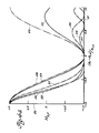
- the magnitude of the Z-axis magnetization M Z for the RF ⁇ -pulse, first form tangential inversion RF sweep and second form tangential inversion RF sweep are graphically compared on a graph that indicates sweep time t swp in milliseconds, along abscissa 42 and the Z-axis magnetization, with respect to the positive Z axis, along ordinate 44.
- the first tangential form sweep final magnetization has a series of lobes 45a, 45b, 45c, ..., each occurring between a pair of adjacent "nulls" 45-1, 45-2, 45-3, ..., at which null times t n1 , t n2 , t n3 , ...the magnetization is essentially at the inversion -1.0 magnitude.
- the RF magnetic field magnitude B 1 is again 0.20G, and for a sweep from an initial frequency of about 2 ⁇ x (20 KHz.) below resonance to a final frequency of about 2 ⁇ x (20 KHz.) greater than resonance, a perfect inversion time t , of about 1.25 mS. is required.
- the final Z-axis magnetization MZ,F' after an attempted perfect inversion by application of a known RF magnetic field B 1 is plotted along ordinate 50 as a function of the fractional error in the RF magnetic field B 1 (with respect to the normal RF magnetic field magnitude B 1,n ) for the ⁇ -pulse, for the first three nodes of the first form tangential AFP sweep and for the second form AFP tangential sweep.
- the magnetization curve 53 (solid line) shows the actual magnetization along the Z axis, with respect to the +Z axis initial magnitude prior to inversion, of a first form AFP inversion frequency sweep terminated at a sweep time equivalent to the node 1 time t nl of Figure 3a.
- Curve 54 (single chain line) is the final Z-axis magnetization for a first form AFP inversion frequency sweep provided for a time interval until the second node time t n2 needed for a B 1,n RF magnetic field.
- Curve 55 (broken line) is the final Z-axis magnetization for a first form AFP inversion frequency sweep extending in time until third node time t n3 .
- Double chain curve 57 illustrates the final magnetization obtained utilizing the second tangential form of AFP frequency sweep, with a sweep time of 2 mS.
- triple-chain curve 59 is the final Z-axis magnetization after a 180° RF ⁇ r-pulse.
- the final Z-axis magnetization value M Z,F is plotted along ordinate 60, while the main static magnetic field B 0 error, or offset, AB O/ B o is plotted, in parts per million, along abscissa 61.
- Curves 63, 64 and 65 illustrate the final Z-axis magnetization sensitivity to main static magnetic field B O error for the first form tangential sweep at nodes 1, 2 and 3, respectively, while curve 67 is the effect of the main static magnetic field offset on the magnetization inversion utilizing the second, and presently preferred, form of tangential AFP inversion frequency sweep.
- Figure 4c illustrates a comparison between predicted and actual results obtained in an NMR imaging system.
- a small vial phantom was placed in the main static magnetic field B 0 of the NMR system and an inversion recovery pulse sequence was run, with the response signal (from the nuclei of the material in the phantom vial) being read out immediately after inversion, so that the response signal amplitude was a direct measure of the completeness of Z-axis magnetization inversion.
- the amplitude of the inverting pulse was varied to produce errors in the RF magnetic field B 1 amplitude.
- Figure 4d illustrates the effect of a main static magnetic field B 0 error, approximated by offsetting the frequency ⁇ 0 of the inverting pulse by a known amount ⁇ 0 .
- the open circle data points 83-1 through 83-9 are the experimental results for nine error values, achieved by providing one of nine constant but different voltage levels into the VCO of apparatus 10.
- the experimental data points 83 are in essential agreement with the predicted response curve 85 for a 180° RF ⁇ -pulse inversion.
- Solid data points 87-1 through 87-9 are the final magnetization values obtained with the same inversion-recovery method and at the same inverting pulse offset frequency values as curve 85.
- the offset frequencies were achieved by offsetting the tangential ramp voltage V c (t) by one of nine different DC levels, prior to introduction into the VCO control voltage input. It will be seen that the first form tangential AFP inversion frequency sweep, second node, data points 87 are also in essential agreement with the theoretical curve 88 therefor.
- the final magnetization values obtained with a second tangential form AFP inversion sweep has data points 89-1 through 89-5 which lie along a curve 90 and again illustrates that inversion by a tan(w s t) tangential AFP sweep is much less sensitive to static field inhomogeneity than inversion by either a first tangential form AFP sweep or a 180° RF ⁇ -pulse.
- Magnetization inversion by a non-linear, tangential frequency sweep for adiabatic fast passage will provide essentially complete magnetization inversion in an inversion time interval on the same order of magnitude as the time interval required for a 180° RF ⁇ -pulse magnetization inversion, and will be considerably less sensitive to inhomogeneities or changes in the main static magnetic field B 0 and/or RF magnetic field B 1 .
- linear ramp generator means can now be subject to modification to provide a non-linear ramp signal having the desired first or second tangential form.
Landscapes
- Physics & Mathematics (AREA)
- General Physics & Mathematics (AREA)
- Condensed Matter Physics & Semiconductors (AREA)
- High Energy & Nuclear Physics (AREA)
- Health & Medical Sciences (AREA)
- Life Sciences & Earth Sciences (AREA)
- Pathology (AREA)
- General Health & Medical Sciences (AREA)
- Medical Informatics (AREA)
- Public Health (AREA)
- Biomedical Technology (AREA)
- Molecular Biology (AREA)
- Surgery (AREA)
- Animal Behavior & Ethology (AREA)
- Engineering & Computer Science (AREA)
- Heart & Thoracic Surgery (AREA)
- Veterinary Medicine (AREA)
- Chemical & Material Sciences (AREA)
- Analytical Chemistry (AREA)
- Biochemistry (AREA)
- Immunology (AREA)
- Magnetic Resonance Imaging Apparatus (AREA)
Applications Claiming Priority (2)
| Application Number | Priority Date | Filing Date | Title |
|---|---|---|---|
| US746146 | 1985-06-18 | ||
| US06/746,146 US4695799A (en) | 1985-06-18 | 1985-06-18 | NMR magnetization inversion by non-linear adiabatic fast passage |
Publications (3)
| Publication Number | Publication Date |
|---|---|
| EP0206129A2 true EP0206129A2 (de) | 1986-12-30 |
| EP0206129A3 EP0206129A3 (en) | 1989-04-19 |
| EP0206129B1 EP0206129B1 (de) | 1992-10-07 |
Family
ID=24999656
Family Applications (1)
| Application Number | Title | Priority Date | Filing Date |
|---|---|---|---|
| EP86107989A Expired - Lifetime EP0206129B1 (de) | 1985-06-18 | 1986-06-11 | Umkehrung der Magnetisierung durch adiabatisch schnellen und nichtlinearen Durchgang bei der magnetischen Kernresonanz |
Country Status (7)
| Country | Link |
|---|---|
| US (1) | US4695799A (de) |
| EP (1) | EP0206129B1 (de) |
| JP (1) | JPS6241650A (de) |
| KR (1) | KR920005506B1 (de) |
| DE (1) | DE3686907T2 (de) |
| FI (1) | FI861470A (de) |
| IL (1) | IL78670A (de) |
Cited By (7)
| Publication number | Priority date | Publication date | Assignee | Title |
|---|---|---|---|---|
| EP0248039A1 (de) * | 1985-11-20 | 1987-12-09 | Max Robin Bendall | Magnetische kernresonanz-messungen durch steuerung des effektiven magnetfeldes. |
| WO1988007673A1 (en) * | 1987-03-27 | 1988-10-06 | Regents Of The University Of Minnesota | Method for rotating nuclear spin magnetization vectors |
| EP0333250A2 (de) * | 1988-03-12 | 1989-09-20 | Philips Patentverwaltung GmbH | Verfahren zur Bestimmung der Kernmagnetisierungsverteilung und Anordnung zur Durchführung des Verfahrens |
| US4947119A (en) * | 1988-06-21 | 1990-08-07 | University Of Minnesota | Magnetic resonance imaging and spectroscopy methods |
| US4988947A (en) * | 1987-03-27 | 1991-01-29 | Regents Of The University Of Minnesota | Amplitude and frequency/phase modulated pulses to achieve plane rotations of nuclear spin magnetization vectors with inhomogeneous B1 |
| US5019784A (en) * | 1989-08-11 | 1991-05-28 | Regents Of The University Of Minnesota | Time symmetric pulse to uniformly rotate magnetization vectors by an arbitrary angle in the presence of large B1 inhomogeneities and resonance offsets |
| WO1991014947A1 (en) * | 1990-03-21 | 1991-10-03 | The General Electric Company, P.L.C. | Nuclear magnetic resonance apparatus |
Families Citing this family (16)
| Publication number | Priority date | Publication date | Assignee | Title |
|---|---|---|---|---|
| JPH01166748A (ja) * | 1987-12-23 | 1989-06-30 | Hitachi Ltd | 高周波磁場の波形の準最適設定方法 |
| JPH03505292A (ja) * | 1988-06-21 | 1991-11-21 | リージェンツ・オブ・ザ・ユニバーシティー・オブ・ミネソタ | 分光方法 |
| DE3851758T2 (de) * | 1988-11-25 | 1995-04-27 | Philips Nv | Kernspinresonanzverfahren und -vorrichtung zur Unterdrückung eines Signals einer chemischen Verschiebungskomponente aus einem längsrelaxationszeitgewichteten Kernspintomogramm. |
| DE68914440T2 (de) * | 1989-04-22 | 1994-07-28 | Spectrospin Ag | Verfahren zur Anregung der transversalen Magnetisierung bei magnetischen Kernresonanz-Impuls-Experimenten. |
| US5412322A (en) * | 1993-06-24 | 1995-05-02 | Wollin Ventures, Inc. | Apparatus and method for spatially ordered phase encoding and for determining complex permittivity in magnetic resonance by using superimposed time-varying electric fields |
| US6448769B1 (en) | 1996-09-10 | 2002-09-10 | General Electric Company | Adiabatic pulse design |
| IL119233A0 (en) * | 1996-09-10 | 1996-12-05 | Elscint Ltd | Frequency selective pulse |
| US6441613B1 (en) * | 1996-09-10 | 2002-08-27 | Ge Medical Systems | Frequency selective pulse |
| DE20109058U1 (de) * | 2001-05-31 | 2002-10-10 | Deltamed Gmbh | Vorrichtung zur Behandlung mit magnetischen Feldern |
| US6958606B2 (en) * | 2003-12-03 | 2005-10-25 | Ge Medical Systems Global Technology Co., Llc | NMR excitation method |
| US7787930B2 (en) * | 2005-04-25 | 2010-08-31 | The United States Of America As Represented By The Department Of Health And Human Services | Adiabatic T2 preparation sequence for magnetic resonance imaging with reduced B1 sensitivity |
| US8502537B2 (en) | 2009-04-02 | 2013-08-06 | Regents Of The University Of Minnesota | Adiabatic magnetization preparation for B1 and B0 insensitive high contrast MRI |
| EP2786380A1 (de) | 2011-12-02 | 2014-10-08 | The Charles Stark Draper Laboratory, Inc. | Atomarer arp-strahlteiler mit frequenzgewobbelten kohärenten laserstrahlpaaren |
| US10585204B2 (en) * | 2012-01-27 | 2020-03-10 | Vista Clara Inc. | Relaxation time estimation in surface NMR |
| CA2929291C (en) * | 2013-12-04 | 2019-07-09 | Exxonmobil Upstream Research Company | Method and system for detection of a material within a region of the earth |
| US9594144B2 (en) | 2014-04-23 | 2017-03-14 | General Electric Company | Low-noise magnetic resonance imaging using low harmonic pulse sequences |
Citations (1)
| Publication number | Priority date | Publication date | Assignee | Title |
|---|---|---|---|---|
| US3826972A (en) * | 1973-08-17 | 1974-07-30 | Univ Leland Stanford Junior | Method and apparatus for detecting nuclear magnetic resonance |
Family Cites Families (4)
| Publication number | Priority date | Publication date | Assignee | Title |
|---|---|---|---|---|
| DE2951537A1 (de) * | 1979-12-20 | 1981-07-02 | Siemens AG, 1000 Berlin und 8000 München | Zeugmatografieverfahren |
| US4565968A (en) * | 1983-02-16 | 1986-01-21 | Albert Macovski | Blood vessel projection imaging system using nuclear magnetic resonance |
| JPS59157551A (ja) * | 1983-02-25 | 1984-09-06 | Asahi Chem Ind Co Ltd | 核スピン反転装置 |
| US4577152A (en) * | 1983-04-11 | 1986-03-18 | Albert Macovski | Selective material projection imaging system using nuclear magnetic resonance |
-
1985
- 1985-06-18 US US06/746,146 patent/US4695799A/en not_active Expired - Fee Related
-
1986
- 1986-04-07 FI FI861470A patent/FI861470A/fi not_active Application Discontinuation
- 1986-05-02 IL IL78670A patent/IL78670A/xx not_active IP Right Cessation
- 1986-06-11 EP EP86107989A patent/EP0206129B1/de not_active Expired - Lifetime
- 1986-06-11 DE DE8686107989T patent/DE3686907T2/de not_active Expired - Fee Related
- 1986-06-18 JP JP61140459A patent/JPS6241650A/ja active Granted
- 1986-06-18 KR KR1019860004842A patent/KR920005506B1/ko not_active IP Right Cessation
Patent Citations (1)
| Publication number | Priority date | Publication date | Assignee | Title |
|---|---|---|---|---|
| US3826972A (en) * | 1973-08-17 | 1974-07-30 | Univ Leland Stanford Junior | Method and apparatus for detecting nuclear magnetic resonance |
Non-Patent Citations (5)
| Title |
|---|
| J. PHYS, E: SCI. INSTRUM., vol. 15, January 1982, pages 74-79, The Institute of Physics; G. JOHNSON et al.: "Instrumentation for NMR spin-warp imaging" * |
| JOURNAL OF CHEMICAL PHYSICS, vol. 79, no. 9, 1st November 1983, pages 4643-4644, American Institute of Physics, US; J. BAUM et al.: "Broadband population inversion by phase modulated pulses" * |
| NATURE, vol. 310, 23rd August 1984, pages 681-683, GB; M.S. SILVER et al.: "Selective population inversion in NMR" * |
| PHYSICAL REVIEW A, vol. 30, no. 4, October 1984, pages 2100-2103, The American Physical Society, US; F.T. HIOE: "Solution of Bloch equations involving amplitude and frequency modulations" * |
| PHYSICAL REVIEW A, vol. 31, no. 4, April 1985, pages 2573-2575, The American Physical Society, US; M.S. SILVER et al.: "Selective spin inversion in nuclear magnetic resonance and coherent optics through an exact solution of the Bloch-Riccati equation" * |
Cited By (10)
| Publication number | Priority date | Publication date | Assignee | Title |
|---|---|---|---|---|
| EP0248039A1 (de) * | 1985-11-20 | 1987-12-09 | Max Robin Bendall | Magnetische kernresonanz-messungen durch steuerung des effektiven magnetfeldes. |
| EP0248039A4 (de) * | 1985-11-20 | 1989-11-14 | Max Robin Bendall | Magnetische kernresonanz-messungen durch steuerung des effektiven magnetfeldes. |
| WO1988007673A1 (en) * | 1987-03-27 | 1988-10-06 | Regents Of The University Of Minnesota | Method for rotating nuclear spin magnetization vectors |
| US4914392A (en) * | 1987-03-27 | 1990-04-03 | Reagents Of The University Of Minnesota | Amplitude and frequency/phase modulated pulses to achieve plane rotations of nuclear spin magnetization vectors with inhomogeneous B1 |
| US4988947A (en) * | 1987-03-27 | 1991-01-29 | Regents Of The University Of Minnesota | Amplitude and frequency/phase modulated pulses to achieve plane rotations of nuclear spin magnetization vectors with inhomogeneous B1 |
| EP0333250A2 (de) * | 1988-03-12 | 1989-09-20 | Philips Patentverwaltung GmbH | Verfahren zur Bestimmung der Kernmagnetisierungsverteilung und Anordnung zur Durchführung des Verfahrens |
| EP0333250A3 (de) * | 1988-03-12 | 1990-12-27 | Philips Patentverwaltung GmbH | Verfahren zur Bestimmung der Kernmagnetisierungsverteilung und Anordnung zur Durchführung des Verfahrens |
| US4947119A (en) * | 1988-06-21 | 1990-08-07 | University Of Minnesota | Magnetic resonance imaging and spectroscopy methods |
| US5019784A (en) * | 1989-08-11 | 1991-05-28 | Regents Of The University Of Minnesota | Time symmetric pulse to uniformly rotate magnetization vectors by an arbitrary angle in the presence of large B1 inhomogeneities and resonance offsets |
| WO1991014947A1 (en) * | 1990-03-21 | 1991-10-03 | The General Electric Company, P.L.C. | Nuclear magnetic resonance apparatus |
Also Published As
| Publication number | Publication date |
|---|---|
| EP0206129B1 (de) | 1992-10-07 |
| KR870000587A (ko) | 1987-02-19 |
| FI861470A0 (fi) | 1986-04-07 |
| IL78670A0 (en) | 1986-08-31 |
| FI861470A (fi) | 1986-12-19 |
| US4695799A (en) | 1987-09-22 |
| DE3686907D1 (de) | 1992-11-12 |
| DE3686907T2 (de) | 1993-05-13 |
| KR920005506B1 (ko) | 1992-07-06 |
| JPH0351171B2 (de) | 1991-08-06 |
| JPS6241650A (ja) | 1987-02-23 |
| EP0206129A3 (en) | 1989-04-19 |
| IL78670A (en) | 1989-10-31 |
Similar Documents
| Publication | Publication Date | Title |
|---|---|---|
| EP0206129A2 (de) | Umkehrung der Magnetisierung durch adiabatisch schnellen und nichtlinearen Durchgang bei der magnetischen Kernresonanz | |
| US4290019A (en) | Methods of deriving image information from objects | |
| EP0086972B2 (de) | NMR-Abbildungsverfahren zur Überwindung der T2*-Effekte in einem inhomogenen statischen magnetischen Feld | |
| US4812760A (en) | Multi-dimensional selective NMR excitation with a single RF pulse | |
| US5541514A (en) | Method for operating a magnetic resonance imaging apparatus | |
| US4947119A (en) | Magnetic resonance imaging and spectroscopy methods | |
| GB2026172A (en) | Method and apparatus for determining the relative densities of nuclei within an object using nuclear magnetic resonance | |
| EP0103397A2 (de) | Verfahren zur Bilderzeugung mittels kernmagnetischer Resonanz | |
| US4301410A (en) | Spin imaging in solids using synchronously rotating field gradients and samples | |
| EP0100183A2 (de) | Kernmagnetische Resonanzmethode und Vorrichtung | |
| CA2004007C (en) | Magnetic resonance signal acquisition methods | |
| US4799014A (en) | Method of setting conditions of high-frequency magnetic field | |
| US4760336A (en) | Variable rate magnetic resonance selective excitation for reducing rf power and specific absorption rate | |
| JPS59107247A (ja) | 核磁気共鳴方法および装置 | |
| US4570120A (en) | N.M.R. Imaging | |
| US5260656A (en) | Method for improving the resolution of solid-state NMR multiple-pulse imaging systems | |
| US5280245A (en) | Magnetic resonance apparatus employing delayed self-refocusing RF excitation | |
| US4703269A (en) | Nuclear magnetic resonance imaging methods and apparatus | |
| US5260654A (en) | Technique for amplitude alignment of NMR spectrometer using multiple pulse sequence that is independent of RF inhomogeneity | |
| US5101158A (en) | Investigating a sample using NMR | |
| US5235280A (en) | Method for determining optimized radio-frequency pulse shapes for selective excitation in magnetic resonance spectroscopy and imaging | |
| WO1995004939A2 (en) | Apparatus and method for decreasing magnetic field sensitivity of long rf pulses | |
| US5300887A (en) | Pulsed field MRI system with spatial selection | |
| NL8502223A (nl) | Werkwijze voor het selektief exciteren van een volume in een objekt. | |
| Oschkinat et al. | A two-dimensional nuclear overhauser enhancement experiment using semiselective soft pulses, and its applications to proteins |
Legal Events
| Date | Code | Title | Description |
|---|---|---|---|
| PUAI | Public reference made under article 153(3) epc to a published international application that has entered the european phase |
Free format text: ORIGINAL CODE: 0009012 |
|
| AK | Designated contracting states |
Kind code of ref document: A2 Designated state(s): CH DE FR GB IT LI NL SE |
|
| PUAL | Search report despatched |
Free format text: ORIGINAL CODE: 0009013 |
|
| AK | Designated contracting states |
Kind code of ref document: A3 Designated state(s): CH DE FR GB IT LI NL SE |
|
| 17P | Request for examination filed |
Effective date: 19890928 |
|
| 17Q | First examination report despatched |
Effective date: 19901031 |
|
| RBV | Designated contracting states (corrected) |
Designated state(s): CH DE FR GB LI NL |
|
| GRAA | (expected) grant |
Free format text: ORIGINAL CODE: 0009210 |
|
| AK | Designated contracting states |
Kind code of ref document: B1 Designated state(s): CH DE FR GB LI NL |
|
| ET | Fr: translation filed | ||
| REF | Corresponds to: |
Ref document number: 3686907 Country of ref document: DE Date of ref document: 19921112 |
|
| PLBE | No opposition filed within time limit |
Free format text: ORIGINAL CODE: 0009261 |
|
| STAA | Information on the status of an ep patent application or granted ep patent |
Free format text: STATUS: NO OPPOSITION FILED WITHIN TIME LIMIT |
|
| 26N | No opposition filed | ||
| PGFP | Annual fee paid to national office [announced via postgrant information from national office to epo] |
Ref country code: FR Payment date: 19940513 Year of fee payment: 9 Ref country code: CH Payment date: 19940513 Year of fee payment: 9 |
|
| PGFP | Annual fee paid to national office [announced via postgrant information from national office to epo] |
Ref country code: DE Payment date: 19940525 Year of fee payment: 9 |
|
| PGFP | Annual fee paid to national office [announced via postgrant information from national office to epo] |
Ref country code: GB Payment date: 19940531 Year of fee payment: 9 |
|
| PGFP | Annual fee paid to national office [announced via postgrant information from national office to epo] |
Ref country code: NL Payment date: 19940630 Year of fee payment: 9 |
|
| PG25 | Lapsed in a contracting state [announced via postgrant information from national office to epo] |
Ref country code: GB Effective date: 19950611 |
|
| PG25 | Lapsed in a contracting state [announced via postgrant information from national office to epo] |
Ref country code: LI Effective date: 19950630 Ref country code: CH Effective date: 19950630 |
|
| PG25 | Lapsed in a contracting state [announced via postgrant information from national office to epo] |
Ref country code: NL Effective date: 19960101 |
|
| GBPC | Gb: european patent ceased through non-payment of renewal fee |
Effective date: 19950611 |
|
| PG25 | Lapsed in a contracting state [announced via postgrant information from national office to epo] |
Ref country code: FR Effective date: 19960229 |
|
| REG | Reference to a national code |
Ref country code: CH Ref legal event code: PL |
|
| NLV4 | Nl: lapsed or anulled due to non-payment of the annual fee |
Effective date: 19960101 |
|
| PG25 | Lapsed in a contracting state [announced via postgrant information from national office to epo] |
Ref country code: DE Effective date: 19960301 |
|
| REG | Reference to a national code |
Ref country code: FR Ref legal event code: ST |