EP0100183A2 - Kernmagnetische Resonanzmethode und Vorrichtung - Google Patents
Kernmagnetische Resonanzmethode und Vorrichtung Download PDFInfo
- Publication number
- EP0100183A2 EP0100183A2 EP83304065A EP83304065A EP0100183A2 EP 0100183 A2 EP0100183 A2 EP 0100183A2 EP 83304065 A EP83304065 A EP 83304065A EP 83304065 A EP83304065 A EP 83304065A EP 0100183 A2 EP0100183 A2 EP 0100183A2
- Authority
- EP
- European Patent Office
- Prior art keywords
- field
- gradient
- values
- value
- slice
- Prior art date
- Legal status (The legal status is an assumption and is not a legal conclusion. Google has not performed a legal analysis and makes no representation as to the accuracy of the status listed.)
- Granted
Links
Images


Classifications
-
- G—PHYSICS
- G01—MEASURING; TESTING
- G01R—MEASURING ELECTRIC VARIABLES; MEASURING MAGNETIC VARIABLES
- G01R33/00—Arrangements or instruments for measuring magnetic variables
- G01R33/20—Arrangements or instruments for measuring magnetic variables involving magnetic resonance
- G01R33/44—Arrangements or instruments for measuring magnetic variables involving magnetic resonance using nuclear magnetic resonance [NMR]
- G01R33/48—NMR imaging systems
- G01R33/483—NMR imaging systems with selection of signals or spectra from particular regions of the volume, e.g. in vivo spectroscopy
- G01R33/485—NMR imaging systems with selection of signals or spectra from particular regions of the volume, e.g. in vivo spectroscopy based on chemical shift information [CSI] or spectroscopic imaging, e.g. to acquire the spatial distributions of metabolites
Definitions
- This invention relates to methods and apparatus for determining the spatial distribution in a body of the chemical shift spectra for a chosen element by nuclear magnetic resonance (NMR) imaging.
- NMR nuclear magnetic resonance
- chemical shift is meant the relatively small shift in the Larmor frequency of a nucleus which is caused by electrons screening the nucleus from an applied magnetic field.
- the exact shielding caused by the electrons depends on the chemical environment of the nucleus, and thus differs for an element in different chemical compounds. NMR techniques have been used to measure chemical shifts for various elements for many years.
- NMR techniques have been used to obtain images representing the spatial distribution over a region of a body of a chosen quantity, e.g. the density of a chosen nuclei, for example hydrogen protons, or of NMR spin relaxation time constants.
- a chosen quantity e.g. the density of a chosen nuclei, for example hydrogen protons
- NMR spin relaxation time constants e.g. the density of a chosen nuclei, for example hydrogen protons
- a method of determining the spatial distribution of the chemical shift spectra of a chosen element across a slice of a body comprises: exciting nuclear magnetic resonance for said element preferentially in said slice of said body; applying first and second pulsed magnetic gradient fields having magnetic field gradients in first and second mutually orthogonal directions in the plane of said slice to produce phase dispersion in said resonance along said first and second directions respectively; stepping the value of the gradient of said first field through a range of first values, for each of said first values stepping the value of the gradient of said first field through a range of first values, for each of said first values stepping the value of the gradient of said second field through a range of second values and measuring the free induction decay signal after each set of one first and second field pulses to form a set of free induction decay signals; subjecting said set of signals to a two dimensional Fourier Transform process with respect to said first and second directions, and to an additional Fourier Transform process with respect to time to obtain chemical- shift spectra for said chosen element
- a method of determining the spatial distribution of the chemical shift spectra of a chosen element over a volume within a body comprises: exciting nuclear magnetic resonance for said element within said volume; applying first, second and third pulsed magnetic gradient fields having magnetic field gradients within said volume in first, second and third mutually orthogonal directions to produce phase dispersion in said resonance along said first, second and third directions respectively; stepping the value of the gradient of said first field through a range of first field values, for each value of said first field values stepping the value of the gradient of said second field through a range of second values, and for each value of said second values stepping the value of the gradient of said third field through a range of third values, and measuring the free induction decay signal after each set of one first, second and third field pulses to form a set of free induction decay signals; subjecting said set of signals to a three dimensional Fourier Transform process, and to an additional Fourier Transform process with respect to time to obtain chemical shift spectra for said chosen element at each of
- a magnetic field pulse is applied which is effective to cause spin echos.
- the invention also provides apparatus arranged: carry out a method according to the first aspect of the present invention, comprising: means arranged to excite nuclear magnetic resonance for said element preferentially in said slice of said body; means arranged to apply first and second pulsed magnetic gradient fields having magnetic field gradients in .first and second mutually orthogonal directions in the plane of said slice; means for stepping the value of the gradient of said first field through a range of first values; means for stepping the value of the gradient of said second field through a range of second values for each of said first values; means for measuring the free induction decay signal after each set of one first and second field pulses.to form a set of free induction decay signals; and means for subjecting said set of signals to a two dimensional Fourier Transform process with respect to said first and second direction, and to an additional Fourier Transform process with respect to time.
- the invention further provides apparatus arranged to carry out a method according to the second aspect of the present invention, comprising: means for exciting nuclear magnetic resonance for said element within said volume; means for applying first, second and third pulsed magnetic gradient fields ' having magnetic field gradients within said volume in first, second and third mutually orthogonal directions; means for stepping the value of the gradient of said first field through a range of first values; means for stepping the value of the gradient of said second field through a second range of second values for each value of said first value; means for stepping the value of the gradient of said third field through a range of third values for each value of said second value; means for measuring the free induction decay signal after each set of one first, second and third field pulses to form a set of free induction decay signals; means for subjecting said set of signals to a three dimensional Fourier Transform process, and to an additional Fourier Transform process with respect to time.
- the apparatus includes a first coil system whereby a magnetic field can be applied to a body to be examined in a given direction, normally designated the Z-direction, with a gradient in any one or more of the three orthogonal directions i.e. X, Y and Z directions.
- the first coil system comprises coils 1 capable of providing a steady uniform magnetic field in the Z .direction; coils 3 capable of providing a magnetic field gradient in the X direction, coils 5 capable of providing a magnetic field gradient in the Y direction; and coils 7 capable of providing a magnetic field gradient in the Z direction.
- the apparatus includes a second coil system 9 whereby RF magnetic fields can be applied to the body under examination in a plane normal to the etion of the steady uniform magnetic field produced by the first coil system, and whereby RF magnetic fields resulting from nuclei in the body under examination which- have been excited to nuclear magnetic resonance with a spin vector component other than in the Z direction can be detected.
- the various coils 1, 3, 5, 7 and 9 are driven by drive amplifiers 11, 12, 13, 15, 17 and 19 respectively, controlled by control circuits 21, 23, 25 and 27 respectively.
- These circuits may take various forms which are well known to those with experience of NMR equipment and other apparatus using coil induced magnetic fields.
- the circuits 21, 23, 25 and 27 are controlled by a central processing and control unit 29 with which are associated inputs and other peripherals 31, for the provision of commands and instructions to the apparatus, and a display 33.
- the NMR signals detected by the coils 9 are applied via an amplifier 35 to a signal handling system 37.
- the signal handling system is arranged to make any appropriate calibration and correction of the signals, but essentially transmits the signals to the processing and control unit 29 wherein the signals are processed for application to the display to produce an image representing the distribution of an NMR quantity in the body being examined.
- the signal handling system 37 may conveniently form part of the unit 29.
- the apparatus also includes field measurement and error signal circuits 39 which receive signals via amplifiers 41 from field probes X" X 2 , Y, and Y 2 which are disposed at suitable positions in relation to a slice 43 of the body being examined, as illustrated in Figure 2, to monitor the applied magnetic fields.
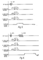
- a steady uniform magnetic field Bo is applied to the body under examination in the Z direction.
- This field serves to define the equilibrium axis of magnetic alignment of the nuclei in the body i.e. along the Z - direction, and remains constant throughout the examination procedure.
- a magnetic gradient field having a gradient G z along the Z - direction is then applied to the body, together with an RF magnetic field pulse denoted B 1 (90°), for reasons explained hereafter.
- the frequency of the RF field is chosen to be the Larmor frequency for phosphorus nuclei in a slice of the body, normal to the Z - direction defined by a particular magnetic field along the Z direction, such that phosphorus nuclei within the slice are preferentially excited.
- the integral of the RF pulse is such that the pulse is just sufficient to tip the spins of the excited phosphorus nuclei into the X-Y plane, and is thus referred to-as a 90° pulse, the spins then precessing in the X-Y plane round the Z axis.
- the gradient Gz is then removed, and replaced by a gradient in the opposite sense - Gz'.
- This causes the rephasing of the spins which have been selectively excited by the combination of the RF pulse B 1 (90 0 ), Bo and the gradient Gz, the dephasing having been caused by the gradient through the slice.
- the magnitude of - Gz' is adjusted so that the spins are rephased at the time at which this gradient is switched off as described, for example, in the above mentioned UK Patent Specification No. 1,578,910.
- Pulsed magnetic gradient fields having gradients Gx, Gy are then simultaneously imposed along the two mutually orthogonal directions X and Y in the plane of the slice of the body. These pulses cause a phase dispersion of the phosphorus nuclei spins in the slice along both the X and Y directions.
- the signal induced in the second coil system by the phosphorus nuclei spins in the slice i.e. the Free Induction Decay (F.I.D.) signal, is recorded.
- the whole pulse sequence i.e. B 1 (90°) and Gz, - Gz', Gx and Gy is then repeated for different values of the amplitude of Gx and Gy, the duration of the pulses being kept constant, and the F.I.D. signal being measured after each pulse sequence.
- the value of the gradient of the Gx pulses is sequentially stepped through the range m ⁇ Gx where m varies from 0 to M-1; for each value of the gradient of Gx, the value of the gradient of the Gy pulse is stepped through the range mAGy where m varies from 0 to N-1. the object being to divide the slice ultimately into N x M pixels.
- the total N x M sets of data stored within the processing and control unit 29 contain information about both the position within the slice (x,y),and the chemical shift structure ( ⁇ ) of the NMR signals from the slice.
- the signal from a point (x,y) in the slice is a function s( ⁇ , ⁇ , x, y, t) where a and ⁇ are the areas under each pulse Gx, Gy for each value of n and m respectively, and t is the time which has elapsed since the end of the Gx, Gy pulses.
- the function s( ⁇ , ⁇ , x, y, t) may be expressed: whereu(x, y,v ) is the chemical shift spectrum for phosphorus nuclei at the point (x,y) in the slice;
- T 2 is the spin-spin relaxation time for the phosphorus nuclei.
- a further Fourier Transform with respect to time will yield the chemical spectrum for phosphorus within each pixel.
- the slice will be divided 1 to 8 x 8 pixels, this being a compromise between spatial resolution, and the necessity to achieve an adequate signal from an element such as phosphorus which may be present in only small quantities in the body.
- the information thus derived may be displayed by any convenient means, such as on the display 33.
- the second method to be described is an adaptation of the first method.
- an additional RF pulse of the same frequency as B 1 (90°) sufficient to cause rotation of the phosphorus nuclei spins within the slice by 180°, and thus referred to as B 1 (180°).
- the spins in the xy plane which have been precessing round the Z axis and have subsequently dephased are caused to rephase to give a rephasing signal, or "spin echo", which is a mirror image of an F.I.D. signal.
- Spin echo which is a mirror image of an F.I.D. signal.
- Recording the spin echos, rather than the F.I.D. signals as in the first method allows further time in which to collect the nuclear magnetic resonance signal after each pulse of Gx and Gy. This reduces the need for very rapid magnetic field switching, with its inherent problem of Eddy currents.
- the third method to be described is an extension of the first method into three dimensions, such that a volume element within the body may be examined, rather than a slice. Consequently the same magnetic fields will be denoted by the same references as in the previous two methods.
- the steady field Bo along the Z - direction is again applied to the body under examination, and an RF pulse B 2 (90°) is applied at the Larmor frequency for phosphorus nuclei at the value of the field Bo.
- this pulse serves to excite all the phosphorus nuclei within the body, and tip their spins into the X-Y planes along the body.
- the three pulsed gradient fields are then applied simultaneously to cause phase dispersion of the spins along the X, Y and Z directions.
- the value of the gradient of the Gz pulse is alsosteppped through a range p ⁇ Gz, where p varies from 0 to P-1, the Gx pulse being stepped through the range m ⁇ Gx for each value of p , whilst the Gy pu.lse is stepped through the range n ⁇ Gy for each value of m.
- the F.I.D. signal induced in the second coil system in the phosphorus spins in the body is recorded, and a B 2 (90°) pulse applied to recommence the sequence.
- the total NxMxP sets of data are subjected to a three dimensional Fourier Transform with respect to the three orthogonal directions X, Y and Z, to obtain frequency distributions for each of the NxMxP pixels within the body.
- a further Fourier Transform, with respect to time, will then yield the chemical shift spectrum for phosphorus within each pixel.
- the fourth method to be described is an adaptation of the third method. After each set of pulses of Gx, Gy and Gz, there is applied an additional RF pulse B 2 (180 o ) effective to cause spin echoes, and as in the second method described herebefore, these are recorded in preference to the F.I.D. signals.
Landscapes
- Physics & Mathematics (AREA)
- Spectroscopy & Molecular Physics (AREA)
- Optics & Photonics (AREA)
- High Energy & Nuclear Physics (AREA)
- Condensed Matter Physics & Semiconductors (AREA)
- General Physics & Mathematics (AREA)
- Magnetic Resonance Imaging Apparatus (AREA)
Applications Claiming Priority (2)
| Application Number | Priority Date | Filing Date | Title |
|---|---|---|---|
| GB8221852 | 1982-07-28 | ||
| GB8221852 | 1982-07-28 |
Publications (3)
| Publication Number | Publication Date |
|---|---|
| EP0100183A2 true EP0100183A2 (de) | 1984-02-08 |
| EP0100183A3 EP0100183A3 (en) | 1985-01-09 |
| EP0100183B1 EP0100183B1 (de) | 1988-12-07 |
Family
ID=10531967
Family Applications (1)
| Application Number | Title | Priority Date | Filing Date |
|---|---|---|---|
| EP83304065A Expired EP0100183B1 (de) | 1982-07-28 | 1983-07-13 | Kernmagnetische Resonanzmethode und Vorrichtung |
Country Status (5)
| Country | Link |
|---|---|
| US (1) | US4553096A (de) |
| EP (1) | EP0100183B1 (de) |
| JP (1) | JPS5943336A (de) |
| DE (1) | DE3378655D1 (de) |
| GB (1) | GB2124388B (de) |
Cited By (8)
| Publication number | Priority date | Publication date | Assignee | Title |
|---|---|---|---|---|
| EP0109633A3 (en) * | 1982-11-22 | 1985-06-26 | General Electric Company | Methods for performing two- and three-dimensional chemical shift imaging |
| EP0155052A1 (de) * | 1984-03-05 | 1985-09-18 | Koninklijke Philips Electronics N.V. | Verfahren zur Verminderung von Artefakten bei der Bilderzeugung mittels Fourier-Zeugmatographie |
| EP0165610A3 (en) * | 1984-06-20 | 1986-10-01 | Hitachi, Ltd. | High speed imaging method with three-dimensional nmr |
| EP0210038A3 (en) * | 1985-07-15 | 1988-02-24 | Technicare Corporation | Chemical shift imaging with field inhomogeneity corrections |
| WO1988006288A1 (en) * | 1987-02-10 | 1988-08-25 | Surrey Medical Imaging Systems Ltd. | Method and apparatus for nmr imaging |
| EP0255220A3 (de) * | 1986-06-27 | 1988-11-30 | Picker International, Inc. | Bilddarstellung mit magnetischer Resonanz |
| EP0298850A1 (de) * | 1987-07-10 | 1989-01-11 | General Electric Cgr S.A. | Verfahren zur Artefaktebeseitigung im NMR-Bildexperiment |
| EP0298849A1 (de) * | 1987-07-10 | 1989-01-11 | General Electric Cgr S.A. | Verfahren zum Wiederaufbau von durch dreidimensionales Experimentieren erworbenen Bildern, insbesondere in NMR |
Families Citing this family (11)
| Publication number | Priority date | Publication date | Assignee | Title |
|---|---|---|---|---|
| FI833807A7 (fi) * | 1983-06-23 | 1984-12-24 | Instrumentarium Oy | Foerfarande foer utredning av aemnets eller magnetfaeltets egenskaper. |
| JPS60194339A (ja) * | 1984-03-15 | 1985-10-02 | Toshiba Corp | 核磁気共鳴装置 |
| GB8415078D0 (en) * | 1984-06-13 | 1984-07-18 | Picker Int Ltd | Nuclear magnetic resonance imaging |
| JPS6129748A (ja) * | 1984-07-20 | 1986-02-10 | Jeol Ltd | 核磁気共鳴測定方法 |
| DE3445689A1 (de) * | 1984-12-14 | 1986-06-19 | Max-Planck-Gesellschaft zur Förderung der Wissenschaften e.V., 3400 Göttingen | Verfahren und einrichtung zur ortsaufgeloesten untersuchung einer probe mittels magnetischer resonanz von spinmomenten |
| US4689563A (en) * | 1985-06-10 | 1987-08-25 | General Electric Company | High-field nuclear magnetic resonance imaging/spectroscopy system |
| US4993414A (en) * | 1985-08-16 | 1991-02-19 | The Board Of Trustees Of The Leland Stanford Junior University | Moving material projection imaging system using nuclear magnetic resonance |
| JPS6253642A (ja) * | 1985-09-02 | 1987-03-09 | 旭化成株式会社 | 核磁気共鳴情報を得る方法 |
| US4714884A (en) * | 1986-06-13 | 1987-12-22 | General Electric Company | Method of eliminating effects of spurious NMR signals caused by imperfect 180 degree RF pulses |
| US4881032A (en) * | 1988-10-21 | 1989-11-14 | General Electric Company | Method of, and apparatus for, NMR spectroscopic metabolite imaging and quantification |
| US5073752A (en) * | 1990-04-19 | 1991-12-17 | Picker International, Inc. | Discrete fourier transform imaging |
Family Cites Families (9)
| Publication number | Priority date | Publication date | Assignee | Title |
|---|---|---|---|---|
| US4339716A (en) * | 1979-05-23 | 1982-07-13 | Picker International Limited | Nuclear magnetic resonance systems |
| GB2056078B (en) * | 1979-08-03 | 1984-02-29 | Emi Ltd | Nuclear magnetic resonance systems |
| US4355282A (en) * | 1979-08-03 | 1982-10-19 | Picker International Limited | Nuclear magnetic resonance systems |
| GB2057142B (en) * | 1979-08-10 | 1983-09-14 | Emi Ltd | Nuclear magnetic resonance systems |
| US4319190A (en) * | 1980-03-06 | 1982-03-09 | Bell Telephone Laboratories, Incorporated | Nuclear magnetic resonance imaging in space and frequency coordinates |
| GB2091884B (en) * | 1981-01-26 | 1984-07-18 | Hinsaw Waldo Stephen | Investigation of samples by nmr techniques |
| US4468621A (en) * | 1982-01-20 | 1984-08-28 | National Research Development Corporation | Investigation of samples by N.M.R. techniques |
| US4431968A (en) * | 1982-04-05 | 1984-02-14 | General Electric Company | Method of three-dimensional NMR imaging using selective excitation |
| US4484138A (en) * | 1982-07-01 | 1984-11-20 | General Electric Company | Method of eliminating effects of spurious free induction decay NMR signal caused by imperfect 180 degrees RF pulses |
-
1983
- 1983-07-13 GB GB08318918A patent/GB2124388B/en not_active Expired
- 1983-07-13 DE DE8383304065T patent/DE3378655D1/de not_active Expired
- 1983-07-13 EP EP83304065A patent/EP0100183B1/de not_active Expired
- 1983-07-19 US US06/515,356 patent/US4553096A/en not_active Expired - Lifetime
- 1983-07-28 JP JP58138667A patent/JPS5943336A/ja active Pending
Cited By (13)
| Publication number | Priority date | Publication date | Assignee | Title |
|---|---|---|---|---|
| EP0109633A3 (en) * | 1982-11-22 | 1985-06-26 | General Electric Company | Methods for performing two- and three-dimensional chemical shift imaging |
| EP0155052A1 (de) * | 1984-03-05 | 1985-09-18 | Koninklijke Philips Electronics N.V. | Verfahren zur Verminderung von Artefakten bei der Bilderzeugung mittels Fourier-Zeugmatographie |
| EP0165610A3 (en) * | 1984-06-20 | 1986-10-01 | Hitachi, Ltd. | High speed imaging method with three-dimensional nmr |
| EP0210038A3 (en) * | 1985-07-15 | 1988-02-24 | Technicare Corporation | Chemical shift imaging with field inhomogeneity corrections |
| EP0255220A3 (de) * | 1986-06-27 | 1988-11-30 | Picker International, Inc. | Bilddarstellung mit magnetischer Resonanz |
| WO1988006288A1 (en) * | 1987-02-10 | 1988-08-25 | Surrey Medical Imaging Systems Ltd. | Method and apparatus for nmr imaging |
| EP0298850A1 (de) * | 1987-07-10 | 1989-01-11 | General Electric Cgr S.A. | Verfahren zur Artefaktebeseitigung im NMR-Bildexperiment |
| EP0298849A1 (de) * | 1987-07-10 | 1989-01-11 | General Electric Cgr S.A. | Verfahren zum Wiederaufbau von durch dreidimensionales Experimentieren erworbenen Bildern, insbesondere in NMR |
| FR2617998A1 (fr) * | 1987-07-10 | 1989-01-13 | Thomson Cgr | Procede de reconstruction d'images acquises par experimentation tridimensionnelle notamment en rmn |
| FR2617999A1 (fr) * | 1987-07-10 | 1989-01-13 | Thomson Cgr | Procede d'elimination d'artefacts dans une experimentation d'imagerie par rmn |
| JPS6427543A (en) * | 1987-07-10 | 1989-01-30 | Gen Electric Cgr | Reconstitution of image obtained by performing three-dimensional measurement especially by nmr |
| US4926124A (en) * | 1987-07-10 | 1990-05-15 | General Electric Cgr S.A. | Method for the removal of artifacts in an NMR imaging experiment |
| US4958282A (en) * | 1987-07-10 | 1990-09-18 | General Electric Cgr S.A. | 3-D image reconstruction using Fourier transformation with differing resolutions of image axes |
Also Published As
| Publication number | Publication date |
|---|---|
| DE3378655D1 (en) | 1989-01-12 |
| US4553096A (en) | 1985-11-12 |
| GB2124388B (en) | 1986-02-12 |
| EP0100183A3 (en) | 1985-01-09 |
| GB8318918D0 (en) | 1983-08-17 |
| GB2124388A (en) | 1984-02-15 |
| JPS5943336A (ja) | 1984-03-10 |
| EP0100183B1 (de) | 1988-12-07 |
Similar Documents
| Publication | Publication Date | Title |
|---|---|---|
| KR100481740B1 (ko) | 와전류들에의해유도된공간적및시간적으로변화하는자계들을측정하고보상하는방법 | |
| EP0100183B1 (de) | Kernmagnetische Resonanzmethode und Vorrichtung | |
| US4563647A (en) | Nuclear magnetic resonance methods and apparatus | |
| US5450010A (en) | Magnetic resonance imaging method and apparatus employing eddy current compensation by modification of gradient size | |
| US4355282A (en) | Nuclear magnetic resonance systems | |
| US4361807A (en) | Nuclear magnetic resonance systems | |
| US5343151A (en) | Method for automatically shimming a high resolution NMR magnet | |
| US4520828A (en) | Nuclear magnetic resonance method and apparatus | |
| US4730620A (en) | Nuclear magnetic resonance method and apparatus for reducing motion artifacts | |
| EP0112663B1 (de) | Magnetische Kernresonanzmethode und Vorrichtung | |
| GB2056078A (en) | Nuclear magnetic resonance systems | |
| US5079505A (en) | Method in the form of a pulse sequence for fast calculation of images of the fat and water distribution in an examination subject on the basis of nuclear magnetic resonance | |
| US4733183A (en) | Nuclear magnetic resonance methods and apparatus | |
| EP0103388B1 (de) | Kernmagnetische Resonanzmethode und Vorrichtung | |
| US4642568A (en) | Nuclear magnetic resonance methods and apparatus | |
| CA2326416C (en) | Recovery of signal void arising from field inhomogeneities in magnetic resonance echo planar imaging | |
| US5602480A (en) | Inspection method and apparatus using nuclear magnetic resonance | |
| US4709211A (en) | Nuclear magnetic resonance system | |
| US4646023A (en) | Nuclear magnetic resonance imaging | |
| US5905377A (en) | Method and apparatus for correcting gradient system and static magnetic field in magnetic resonance imaging | |
| US4801884A (en) | Apparatus for the identification of nuclear magnetic spectra from spatially selectable regions of an examination subject | |
| US4683432A (en) | Nuclear magnetic resonance methods and apparatus | |
| EP0106472B1 (de) | Magnetische Kernresonanzmethode und -vorrichtung | |
| US5387866A (en) | Methods for high-speed measurement of spin-lattice relaxation times | |
| EP0129356A2 (de) | Magnetische Kernresonanzmethode und Vorrichtung |
Legal Events
| Date | Code | Title | Description |
|---|---|---|---|
| PUAI | Public reference made under article 153(3) epc to a published international application that has entered the european phase |
Free format text: ORIGINAL CODE: 0009012 |
|
| AK | Designated contracting states |
Designated state(s): DE FR NL |
|
| PUAL | Search report despatched |
Free format text: ORIGINAL CODE: 0009013 |
|
| AK | Designated contracting states |
Designated state(s): DE FR NL |
|
| 17P | Request for examination filed |
Effective date: 19850708 |
|
| 17Q | First examination report despatched |
Effective date: 19861127 |
|
| GRAA | (expected) grant |
Free format text: ORIGINAL CODE: 0009210 |
|
| AK | Designated contracting states |
Kind code of ref document: B1 Designated state(s): DE FR NL |
|
| REF | Corresponds to: |
Ref document number: 3378655 Country of ref document: DE Date of ref document: 19890112 |
|
| ET | Fr: translation filed | ||
| PGFP | Annual fee paid to national office [announced via postgrant information from national office to epo] |
Ref country code: FR Payment date: 19890629 Year of fee payment: 7 |
|
| PGFP | Annual fee paid to national office [announced via postgrant information from national office to epo] |
Ref country code: NL Payment date: 19890731 Year of fee payment: 7 |
|
| PLBI | Opposition filed |
Free format text: ORIGINAL CODE: 0009260 |
|
| PGFP | Annual fee paid to national office [announced via postgrant information from national office to epo] |
Ref country code: DE Payment date: 19890925 Year of fee payment: 7 |
|
| 26 | Opposition filed |
Opponent name: SIEMENS AKTIENGESELLSCHAFT, BERLIN UND MUENCHEN Effective date: 19890907 Opponent name: N.V. PHILIPS' GLOEILAMPENFABRIEKEN Effective date: 19890906 |
|
| NLR1 | Nl: opposition has been filed with the epo |
Opponent name: SIEMENS AKTIENGESELLSCHAFT,BERLIN UND MUENCHEN Opponent name: N.V. PHILIPS' GLOEILAMPENFABRIEKEN |
|
| RDAG | Patent revoked |
Free format text: ORIGINAL CODE: 0009271 |
|
| STAA | Information on the status of an ep patent application or granted ep patent |
Free format text: STATUS: PATENT REVOKED |
|
| NLV4 | Nl: lapsed or anulled due to non-payment of the annual fee | ||
| 27W | Patent revoked |
Effective date: 19901206 |
|
| REG | Reference to a national code |
Ref country code: FR Ref legal event code: ST |