EP0205185A2 - Objective with spectrometer in the electron beam measuring technique - Google Patents
Objective with spectrometer in the electron beam measuring technique Download PDFInfo
- Publication number
- EP0205185A2 EP0205185A2 EP86108126A EP86108126A EP0205185A2 EP 0205185 A2 EP0205185 A2 EP 0205185A2 EP 86108126 A EP86108126 A EP 86108126A EP 86108126 A EP86108126 A EP 86108126A EP 0205185 A2 EP0205185 A2 EP 0205185A2
- Authority
- EP
- European Patent Office
- Prior art keywords
- spectrometer
- secondary electrons
- lens
- sample
- objective lens
- Prior art date
- Legal status (The legal status is an assumption and is not a legal conclusion. Google has not performed a legal analysis and makes no representation as to the accuracy of the status listed.)
- Granted
Links
- 238000010894 electron beam technology Methods 0.000 title claims abstract description 11
- 238000000034 method Methods 0.000 title 1
- 230000003287 optical effect Effects 0.000 claims abstract description 17
- 230000005684 electric field Effects 0.000 claims description 8
- 230000001960 triggered effect Effects 0.000 claims description 5
- 238000007654 immersion Methods 0.000 claims description 3
- 238000005259 measurement Methods 0.000 claims description 3
- 230000001133 acceleration Effects 0.000 claims description 2
- 238000005516 engineering process Methods 0.000 claims description 2
- 238000001514 detection method Methods 0.000 claims 1
- 239000000523 sample Substances 0.000 abstract description 22
- 230000000694 effects Effects 0.000 abstract description 6
- 230000002349 favourable effect Effects 0.000 abstract description 3
- 239000008186 active pharmaceutical agent Substances 0.000 description 6
- 230000003993 interaction Effects 0.000 description 3
- 230000008901 benefit Effects 0.000 description 2
- 238000011161 development Methods 0.000 description 2
- 230000018109 developmental process Effects 0.000 description 2
- 230000009467 reduction Effects 0.000 description 2
- 239000007787 solid Substances 0.000 description 2
- 239000000126 substance Substances 0.000 description 2
- 230000002411 adverse Effects 0.000 description 1
- 230000004075 alteration Effects 0.000 description 1
- 239000004020 conductor Substances 0.000 description 1
- 238000010276 construction Methods 0.000 description 1
- 230000001419 dependent effect Effects 0.000 description 1
- 230000006872 improvement Effects 0.000 description 1
- 238000011835 investigation Methods 0.000 description 1
- 230000005855 radiation Effects 0.000 description 1
- 238000007493 shaping process Methods 0.000 description 1
Images

Classifications
-
- H—ELECTRICITY
- H01—ELECTRIC ELEMENTS
- H01J—ELECTRIC DISCHARGE TUBES OR DISCHARGE LAMPS
- H01J49/00—Particle spectrometers or separator tubes
- H01J49/02—Details
- H01J49/06—Electron- or ion-optical arrangements
-
- G—PHYSICS
- G01—MEASURING; TESTING
- G01R—MEASURING ELECTRIC VARIABLES; MEASURING MAGNETIC VARIABLES
- G01R31/00—Arrangements for testing electric properties; Arrangements for locating electric faults; Arrangements for electrical testing characterised by what is being tested not provided for elsewhere
- G01R31/28—Testing of electronic circuits, e.g. by signal tracer
- G01R31/302—Contactless testing
- G01R31/305—Contactless testing using electron beams
-
- H—ELECTRICITY
- H01—ELECTRIC ELEMENTS
- H01J—ELECTRIC DISCHARGE TUBES OR DISCHARGE LAMPS
- H01J37/00—Discharge tubes with provision for introducing objects or material to be exposed to the discharge, e.g. for the purpose of examination or processing thereof
- H01J37/02—Details
- H01J37/04—Arrangements of electrodes and associated parts for generating or controlling the discharge, e.g. electron-optical arrangement, ion-optical arrangement
- H01J37/147—Arrangements for directing or deflecting the discharge along a desired path
- H01J37/1472—Deflecting along given lines
- H01J37/1474—Scanning means
-
- H—ELECTRICITY
- H01—ELECTRIC ELEMENTS
- H01J—ELECTRIC DISCHARGE TUBES OR DISCHARGE LAMPS
- H01J37/00—Discharge tubes with provision for introducing objects or material to be exposed to the discharge, e.g. for the purpose of examination or processing thereof
- H01J37/26—Electron or ion microscopes; Electron or ion diffraction tubes
- H01J37/266—Measurement of magnetic- or electric fields in the object; Lorentzmicroscopy
- H01J37/268—Measurement of magnetic- or electric fields in the object; Lorentzmicroscopy with scanning beams
-
- H—ELECTRICITY
- H01—ELECTRIC ELEMENTS
- H01J—ELECTRIC DISCHARGE TUBES OR DISCHARGE LAMPS
- H01J49/00—Particle spectrometers or separator tubes
- H01J49/44—Energy spectrometers, e.g. alpha-, beta-spectrometers
- H01J49/46—Static spectrometers
- H01J49/48—Static spectrometers using electrostatic analysers, e.g. cylindrical sector, Wien filter
- H01J49/488—Static spectrometers using electrostatic analysers, e.g. cylindrical sector, Wien filter with retarding grids
Definitions
- the invention relates to a spectrometer lens for electron beam measurement technology according to the preamble of claim 1.
- This known arrangement is a magnetic objective lens with a short focal length with an integrated parallel plate analyzer and an electrode arranged above the objective lens for deflecting the secondary electrons in the direction of a detector.
- the diameter of the electron probe on the sample can be significantly reduced in comparison with conventional arrangements in an electron beam measuring device equipped with the known spectrometer objective, the spatial resolution of these devices remains limited. The reason for this is the Coulomb repulsion of the electrons in the beam path between the electron source and the sample, which counteracts a focusing of the electron beam.
- the invention has for its object to provide a spectrometer lens of the type mentioned, with which the electron-optical beam path between the beam generator and the sample is shortened and thus the influence of the Boersch effect on the probe diameter can be significantly reduced.
- the advantage that can be achieved with the invention is, in particular, that the spatial and potential resolution of an electron beam measuring device can be significantly increased even with high probe currents.
- the primary electrons are deflected within the spectrometer objective, so that the space for the two-stage deflection systems between the condenser lens and the objective lens used in conventional arrangements can be saved.
- the extremely short overall length of the electron beam measuring device that can be achieved in this way in turn has a favorable effect on the influence of the lateral Boersch effect on the probe diameter that increases with the length of the beam path.
- Claims 2 to 7 are directed to preferred refinements and developments of the invention.
- the exemplary embodiment of a spectrometer objective according to the invention shown in FIGS. 1 and 2 consists of a short focal length, largely asymmetrical objective lens OL with an integrated electrostatic counterfield spectrometer and a single-stage magnetic deflection system DS arranged symmetrically to the optical axis OA within the magnetic lens OL.
- This overall system forms an electron-optical unit with which both the primary electrons PE generated, for example, in a high-current electron source Q and the secondary electrons SE triggered on a sample PR are focused into a point lying on the optical axis OA.
- the electron source Q or the intermediate image ZP of the source Q reduced by condenser lenses KL is reduced again with the aid of the spectrometer lens as part of the beam-shaping system onto a sample PR arranged in the immediate vicinity of the rear focal plane of the objective lens OL.
- the use of short focal length objective lenses offers a number of advantages. As a result of the. Focal lengths between 3 and 12 mm achievable high lens reduction, the required system reduction can be achieved by a short beam path. However, a short beam path is of crucial importance, especially for reducing the adverse effects of the electron-electron interaction on the probe diameter.
- objective lenses with a short focal length are distinguished in particular by smaller axial color and aperture errors which increase with the focal length.
- these secondary electrons SE are in the electric field of a grid electrode G1 lying at a high positive potential V e between 1 and 5 kV aspirated and accelerated in the direction of the optical axis OA.
- the secondary electrons SE pass through this flat grid electrode G1 with high energies and are focused in the magnetic field of the objective lens OL into a point ZS located on the optical axis OA within the spectrometer objective.
- the position of this focusing point ZS is determined by the level of the voltage V e of the grid electrode G1 and the strength of the magnetic field between the pole pieces of the objective lens OL, which is dependent on the primary electron energy.
- the disadvantageous influence of the Boersch effect on the probe diameter is also reduced in this part of the beam path.
- the opening and color errors of the magnetic lens OL are reduced as a result of the superimposition of the focusing magnetic field of the objective lens and the electrical field of the suction electrode G1 which brakes the primary electrons PE.
- the braking and energy analysis of the secondary electrons SE takes place directly above the objective lens OL in a preferably spherically symmetrical electrical opposing field, which is built up in the spatial area between two spherically symmetrical network electrodes K1 and K2 which have different potentials V E and V G.
- Such electrode arrangements are known, for example, from US Pat. No. 4,464,571.
- the lower, spherically symmetrical network electrode K1 is conductively connected to the suction electrode G1 via a hollow cylinder HZ arranged concentrically to the optical axis OA.
- the potential V a of the upper network electrode K2, which acts as an opposing field grid, is determined by the sample potential and is typically between approximately 0 and minus 20 volts.
- the secondary electron lobe is tilted around the center M of the deflection system DS when the electron probe is rasterized, it is possible to detect the secondary electrons SE emitted in the direction of the axis of symmetry of the lobe with one or more detectors DT arranged symmetrically to the optical axis OA.
- a grating AE lying at a negative potential can also be provided above the spherically symmetrical network electrodes K1 and K2 for deflecting the secondary electrons SE emitted in the direction of the optical axis OA.
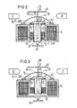
- the embodiment of a spectrometer lens according to the invention shown in FIG. 3 consists of a short focal length magnetic objective lens OL with an integrated electrostatic counterfield spectrometer and one within the Magnetic lens OL arranged single-stage deflection system DS.
- the suction and acceleration of the secondary electrons SE takes place in the field of an electrostatic immersion lens, which consists of the spherically symmetrical network electrode K1, the hollow cylinder HZ arranged concentrically to the optical axis OA, and the pole shoes lying at earth potential of the objective lens OL.
- This combination of a magnetic lens with a superimposed electrical immersion lens is distinguished from arrangements with only one magnetic lens by more favorable color error values.
Abstract
Das erfindungsgemäße Spektrometer-Objektiv besteht aus einer kurzbrennweitigen, asymmetrischen Objektivlinse (OL) mit integriertem elektrostatischen Gegenfeld-Spektrometer und einem einstufigen, innerhalb der Magnetlinse angeoordneten Ablenkystem (DS). Da die Ablenkung der Primärelektronen (PE) innerhalb des Spektrometer-Objektivs erfolgt, kann der Raum für die in konventionellen Anordnungen verwendeten zweistufigen Ablenksysteme zwischen Kondensor- (KL) und Objektivlinse (OL) eingespart werden. Die hierdurch erreichbare extrem kurze Baulänge des Elektronenstrahl-Meßgerätes wirkt sich wiederum günstig auf den mit der Länge des elektronenoptischen Strahlenganges anwachsenden Einfluß des lateralen Boersch-Effekts auf den Sondendurchmesser aus.The spectrometer objective according to the invention consists of a short focal length, asymmetrical objective lens (OL) with an integrated electrostatic counterfield spectrometer and a single-stage deflection system (DS) arranged within the magnetic lens. Since the primary electrons (PE) are deflected within the spectrometer objective, the space for the two-stage deflection systems between the condenser (KL) and objective (OL) lenses used in conventional arrangements can be saved. The extremely short overall length of the electron beam measuring device that can be achieved in this way in turn has a favorable effect on the influence of the lateral Boersch effect on the probe diameter that increases with the length of the electron optical beam path.
Description
Die Erfindung betrifft ein Spektrometer-Objektiv für die Elektronenstrahl-Meßtechnik nach dem Oberbegriff des Patentanspruchs 1.The invention relates to a spectrometer lens for electron beam measurement technology according to the preamble of
Für quantitative Potentialmessungen an Knotenpunkten und Leiterbahnen in hochintegrierten Schaltungen werden gegenwärtig konventionelle, mit Strahlaustastsystemen und Gegenfeld-Spektrometem ausgerüstete Raster-Elektronenmikroskope eingesetzt. Mit modifizierten Raster-Elektronenmikroskopen lassen sich allerdings genügend feine Elektronensonden zur Untersuchung höchstintegrierter Schaltungen mit Strukturen im Sub-Mikrometerbereich nicht herstellen, da diese Geräte zur Vermeidung von Strahlenschäden und Aufladungen der zumeist auf isolierenden Trägersubstanzen angeordneten Bauelemente bei niedrigen Primärelektronen-Energien betrieben werden müssen. Eine deutliche Verbesserung der im wesentlichen durch den axialen Farbfehler der Objektivlinse und die Elektron-Elektron-Wechselwirkung (Boersch-Effekt) begrenzten Ortsauflösung ist nur durch einen kurzen elektronenoptischen Strahlengang mit wenigen Strahlüberkreuzungspunkten und einer Objektivlinse kurzer Brennweite erreichbar. Der Einsatz kurzbrennweitiger Objektiviinsen zur Reduktion der proportional mit der Brennweite anwachsenden axialen Farbfehler scheiterte bisher am Aufbau konventioneller Elektronenstrahl-Meßgeräte, bei denen zwischen Objektivlinse und Probe ein Sekundärelektronen-Spektrometer angeordnet ist.Conventional scanning electron microscopes equipped with beam blanking systems and counterfield spectrometers are currently used for quantitative potential measurements at nodes and conductor tracks in highly integrated circuits. With modified scanning electron microscopes, however, it is not possible to produce sufficiently fine electron probes for the investigation of highly integrated circuits with structures in the sub-micrometer range, since these devices have to be operated at low primary electron energies in order to avoid radiation damage and charging of the components, which are usually arranged on insulating carrier substances. A significant improvement in the spatial resolution, which is essentially limited by the axial color error of the objective lens and the electron-electron interaction (Boersch effect), can only be achieved by a short electron-optical beam path with few beam crossing points and an objective lens with a short focal length. The use of short focal length objective lenses to reduce the axial color errors that increase proportionally with the focal length has hitherto failed due to the construction of conventional electron beam measuring devices in which a secondary electron spectrometer is arranged between the objective lens and the sample.
Erst durch die Entwicklung von Objektivlinsen mit integriertem Sekundärelektronen-Spektrometer (Spektrometer-Objektive) konnte mit dem Arbeitsabstand die Aberration der Objektivlinse reduziert und damit der Sondendurchmesser auf der Probe verkleinert werden. Ein solches Spektrometer-Objektiv ist aus der Veröffentlichung von Kawamoto, "Electron Beam Tester with In-the-Lens-Analyzer" in den Proceedings of the Symposium on Electron-Beam-Testing, 9. bis 10. Nov. 1984, Osaka, Japan (Seite 69-72) bekannt.It was only through the development of objective lenses with an integrated secondary electron spectrometer (spectrometer objectives) that the aberration of the objective lens could be reduced with the working distance and thus the probe diameter on the sample reduced. Such a spectrometer lens is from the publication by Kawamoto, "Electron Beam Tester with In-the-Lens-Analyzer" in the Proceedings of the Symposium on Electron-Beam-Testing, November 9-10, 1984, Osaka, Japan (Page 69-72).
Bei dieser bekannten Anordnung handelt es sich um eine magnetische Objektivlinse kurzer Brennweite mit integriertem Parallelplatten-Analysator und einer oberhalb der Objektivlinse angeordneten Elektrode zur Ablenkung der Sekundärelektronen in Richtung eines Detektors.This known arrangement is a magnetic objective lens with a short focal length with an integrated parallel plate analyzer and an electrode arranged above the objective lens for deflecting the secondary electrons in the direction of a detector.
Obwohl der Durchmesser der Elektronensonde auf der Probe in einem mit dem bekannten Spektrometer-Objektiv ausgerüsteten Elektronenstrahl-Meßgerät gegenüber konventionellen Anordnungen deutlich verringert werden kann, bleibt die Ortsauflösung dieser Geräte begrenzt. Ursache hierfür ist die einer Fokussierung des Elektronenstrahls entgegenwirkende Coulomb-Abstoßung der Elektronen im Strahlengang zwischen Elektronenquelle und Probe.Although the diameter of the electron probe on the sample can be significantly reduced in comparison with conventional arrangements in an electron beam measuring device equipped with the known spectrometer objective, the spatial resolution of these devices remains limited. The reason for this is the Coulomb repulsion of the electrons in the beam path between the electron source and the sample, which counteracts a focusing of the electron beam.
Der Erfindung liegt die Aufgabe zugrunde, ein Spektrometer-Objektiv der eingangs genannten Art anzugeben, mit dem der elektronenoptische Strahlengang zwischen Strahlerzeuger und Probe verkürzt und damit der Einfluß des Boersch-Effektes auf den Sondendurchmesser deutlich verringert werden kann.The invention has for its object to provide a spectrometer lens of the type mentioned, with which the electron-optical beam path between the beam generator and the sample is shortened and thus the influence of the Boersch effect on the probe diameter can be significantly reduced.
Diese Aufgabe wird erfindungsgemäß durch ein Spektrometer-Objektiv der eingangs genannten Art gelöst, welches die kennzeichnenden Merkmale des Patentanspruchs 1 aufweist.This object is achieved according to the invention by a spectrometer lens of the type mentioned at the outset, which has the characterizing features of
Der mit der Erfindung erzielbare Vorteil besteht insbesondere darin, daß die Orts-und Potentialauflösung eines Elektronenstrahl-Meßgerätes auch bei hohen Sondenströmen deutlich gesteigert werden kann. Erfindungsgemäß erfolgt die Ablenkung der Primärelektronen innerhalb des Spektrometer-Objektivs, so daß der Raum für die in konventionellen Anordnungen verwendeten zweistufigen Ablenksysteme zwischen Kondensor-und Objektivlinse eingespart werden kann. Die hierdurch erreichbare extrem kurze Baulänge des Elektronenstrahl-Meßgerätes wirkt sich wiederum günstig auf den mit der Länge des Strahlenganges wachsenden Einfluß des lateralen Boersch-Effektes auf den Sondendurchmesser aus.The advantage that can be achieved with the invention is, in particular, that the spatial and potential resolution of an electron beam measuring device can be significantly increased even with high probe currents. According to the invention, the primary electrons are deflected within the spectrometer objective, so that the space for the two-stage deflection systems between the condenser lens and the objective lens used in conventional arrangements can be saved. The extremely short overall length of the electron beam measuring device that can be achieved in this way in turn has a favorable effect on the influence of the lateral Boersch effect on the probe diameter that increases with the length of the beam path.
Die Patentansprüche 2 bis 7 sind auf bevorzugte Ausgestaltungen und Weiterbildungen der Erfindung gerichtet.Claims 2 to 7 are directed to preferred refinements and developments of the invention.
Das erfindungsgemäße Spektrometer-Objektiv wird nachfolgend anhand der Zeichnung erläutert. Dabei zeigen die
- Fig. 1 bis 3 Ausführungsbeispiele erfindungsgemäßer Spektrometer-Objektive mit integriertem einstufigen Ablenksystem.
- 1 to 3 exemplary embodiments of spectrometer objectives according to the invention with an integrated single-stage deflection system.
Das in den Fig.1 und 2 dargestellte Ausführungsbeispiel eines erfindungsgemäßen Spektrometer-Objektivs besteht aus einer kurzbrennweitigen, weitgehend asymmetrischen Objektiviinse OL mit integriertem elektrostatischen Gegenfeld-Spektrometer und einem einstufigen, innerhalb der Magnetlinse OL symmetrisch zur optischen Achse OA angeordneten magnetischen Ablenksystem DS. Dieses Gesamtsystem bildet eine elektronenoptische Einheit, mit der sowohl die beispielsweise in einer Hochstrom-Elektronenquelle Q erzeugten Primärelektronen PE als auch die auf einer Probe PR ausgelösten Sekundärelektronen SE in einen auf der optischen Achse OA liegenden Punkt fokussiert werden. Zur Erzeugung einer feinen Elektronensonde bildet man die Elektronenquelle Q oder das durch Kondensorlinsen KL verkleinerte Zwischenbild ZP der Quelle Q mit Hilfe des Spektrometer-Objektivs als Teil des strahlformenden Systems nochmals verkleinert auf eine in unmittelbarer Nähe der hinteren Brennebene der Objektivlinse OL angeordnete Probe PR ab. Die Verwendung von Objektivlinsen kurzer Brennweite bietet eine Reihe von Vorteilen. Infolge der bei. Brennweiten zwischen 3 und 12 mm erreichbaren hohen Objektivverkleinerung kann die geforderte Systemverkleinerung durch einen kurzen Strahlengang realisiert werden. Ein kurzer Strahlengang ist aber gerade für eine Reduktion der nachteiligen Einflüsse der Elektron-Elektron-Wechselwirkung auf den Sondendurchmesser von entscheidender Bedeutung. Zusätzlich zeichnen sich Objektivlinsen kurzer Brennweite insbesondere durch geringere mit der Brennweite anwachsende axiale Farb-und Öffnungsfehler aus.The exemplary embodiment of a spectrometer objective according to the invention shown in FIGS. 1 and 2 consists of a short focal length, largely asymmetrical objective lens OL with an integrated electrostatic counterfield spectrometer and a single-stage magnetic deflection system DS arranged symmetrically to the optical axis OA within the magnetic lens OL. This overall system forms an electron-optical unit with which both the primary electrons PE generated, for example, in a high-current electron source Q and the secondary electrons SE triggered on a sample PR are focused into a point lying on the optical axis OA. To generate a fei NEN electron probe, the electron source Q or the intermediate image ZP of the source Q reduced by condenser lenses KL is reduced again with the aid of the spectrometer lens as part of the beam-shaping system onto a sample PR arranged in the immediate vicinity of the rear focal plane of the objective lens OL. The use of short focal length objective lenses offers a number of advantages. As a result of the. Focal lengths between 3 and 12 mm achievable high lens reduction, the required system reduction can be achieved by a short beam path. However, a short beam path is of crucial importance, especially for reducing the adverse effects of the electron-electron interaction on the probe diameter. In addition, objective lenses with a short focal length are distinguished in particular by smaller axial color and aperture errors which increase with the focal length.
Zum Nachweis der am Meßpunkt von den hochenergetischen Primärelektronen PE infolge ihrer Wechselwirkung mit der Festkörpersubstanz ausgelösten und in einen großen Raumwinkelbereich oberhalb der Probe PR emittierten niederenergetischen Sekundärelektronen SE werden diese im elektrischen Feld einer auf hohem positiven Potential Ve zwischen 1 und 5 kV liegenden Gitterelektrode G1 abgesaugt und in Richtung der optischen Achse OA beschleunigt. Die Sekundärelektronen SE durchlaufen diese ebene Gitterelektrode G1 mit hohen Energien und werden im Magnetfeld der Objektivlinse OL in einen auf der optischen Achse OA innerhalb des Spektrometer-Objektivs liegenden Punkt ZS fokussiert. Die Lage dieses Fokussierungspunktes ZS wird bestimmt von der Höhe der Spannung Ve der Gitterelektrode G1 und der von der Primärelektronen-Energie abhängigen Stärke des Magnetfeldes zwischen den Polschuhen der Objektivlinse OL. Die gemeinsame Fokussierung aller Sekundärelektronen SE im Feld der Objektivlinse OL ist überhaupt nur durch deren Beschleunigung auf hohe kinetische Energien möglich, da nur dann die relative Energiebreite A E/ E ( E = mittlere kinetische Energie der Sekundärelektronen) so weit reduziert wird, daß die Bildweiten der am Meßpunkt mit unterschiedlichen Energien E emittierten Sekundärelektronen SE noch nahezu zusammenfallen. Da auch die Primärelektronen PE bei hohen Absaugspannungen VE die Objektivlinse OL mit hohen Energien durchlaufen, wird in diesem Teil des Strahlenganges auch der nachteilige Einfluß des Boersch-Effekts auf den Sondendurchmesser reduziert. Außerdem verringern sich infolge der Überlagerung des fokussierenden Magnetfeldes der Objektivlinse und des die Primärelektronen PE abbremsenden elektrischen Feldes der Absaugelektrode G1 die Öffnungs-und Farbfehler der Magnetlinse OL.To detect the low-energy secondary electrons SE released at the measuring point by the high-energy primary electrons PE as a result of their interaction with the solid substance and emitted in a large solid angle range above the sample PR, these secondary electrons SE are in the electric field of a grid electrode G1 lying at a high positive potential V e between 1 and 5 kV aspirated and accelerated in the direction of the optical axis OA. The secondary electrons SE pass through this flat grid electrode G1 with high energies and are focused in the magnetic field of the objective lens OL into a point ZS located on the optical axis OA within the spectrometer objective. The position of this focusing point ZS is determined by the level of the voltage V e of the grid electrode G1 and the strength of the magnetic field between the pole pieces of the objective lens OL, which is dependent on the primary electron energy. The common focusing of all secondary electrons SE in the field of the objective lens OL is only possible by accelerating them to high kinetic energies, since only then is the relative energy width AE / E (E = average kinetic energy of the secondary electrons) reduced to such an extent that the image widths of the secondary electrons SE emitted at the measuring point with different energies E still almost coincide. Since the primary electrons PE also pass through the objective lens OL with high energies at high suction voltages V E , the disadvantageous influence of the Boersch effect on the probe diameter is also reduced in this part of the beam path. In addition, the opening and color errors of the magnetic lens OL are reduced as a result of the superimposition of the focusing magnetic field of the objective lens and the electrical field of the suction electrode G1 which brakes the primary electrons PE.
Die Abbremsung und Energieanalyse der Sekundärelektronen SE erfolgt unmittelbar oberhalb der Objektiviinse OL in einem vorzugsweise kugelsymmetrischen elektrischen Gegenfeld, das in dem Raumbereich zwischen zwei kugelsymmetrischen, auf unterschiedlichem Potential VE bzw. VG liegenden Netzelektroden K1 und K2 aufgebaut wird. Derartige Elektrodenanordnungen sind beispielsweise aus der US-PS 4 464 571 bekannt.The braking and energy analysis of the secondary electrons SE takes place directly above the objective lens OL in a preferably spherically symmetrical electrical opposing field, which is built up in the spatial area between two spherically symmetrical network electrodes K1 and K2 which have different potentials V E and V G. Such electrode arrangements are known, for example, from US Pat. No. 4,464,571.
Zur Erzeugung eines von elektrischen Feldern freien Raumes innerhalb der Objektivlinse OL ist die untere, kugelsymmetrische Netzelektrode K1 über einen konzentrisch zur optischen Achse OA angeordneten Hohlzylinder HZ leitend mit der Absaugelektrode G1 verbunden. Das Potential Va der oberen, als Gegenfeld-Gitter wirkenden Netzelektrode K2 wird durch das Probenpotential festgelegt und liegt typischerweise zwischen etwa 0 und minus 20 Volt.To generate a space free of electric fields within the objective lens OL, the lower, spherically symmetrical network electrode K1 is conductively connected to the suction electrode G1 via a hollow cylinder HZ arranged concentrically to the optical axis OA. The potential V a of the upper network electrode K2, which acts as an opposing field grid, is determined by the sample potential and is typically between approximately 0 and minus 20 volts.
Da sowohl die Primärelektronen PE als auch die von der Probe PR emittierten und im Feld der Absaugelektrode G1 beschleunigten Sekundärelektronen SE durch das integrierte Ablenksystem DS abgelenkt werden, ist darauf zu achten, daß die Sekundärelektronen-Trajektorien möglichst parallel zu den elektrischen Feldlinien des Gegenfeldes und damit senkrecht zur Oberfläche der kugelsymmetrischen Netzelektroden K1 und K2 verlaufen. Diese Bedingung ist für den Zentralstrahl der Sekundärelektronenkeule immer erfüllt, falls der gemeinsame Mittelpunkt der kugelsymmetrischen Netzelektroden K1 und K2 auf der optischen Achse OA in der Mitte M des Ablenksystems DS liegt. Da die Sekundärelektronenkeule beim Rastern der Elektronensonde um die Mitte M des Ablenksystems DS gekippt wird, ist ein orts-und winkelunabhängiger Nachweis der in Richtung der Symmetrieachse der Keule emittierten Sekundärelektronen SE mit einem oder mehreren symmetrisch zur optischen Achse OA angeordneten Detektoren DT möglich. Bei einer symmetrischen Anordnung der beispielsweise aus Abschirmgitter, Szintillator und Lichtleiter bestehenden Detektoren DT kann oberhalb der kugelsymmetrischen Netzelektroden K1 und K2 noch ein auf negativem Potential liegendes Gitter AE zur Ablenkung der in Richtung der optischen Achse OA emittierten Sekundärelektronen SE vorgesehen sein.Since both the primary electrons PE and the secondary electrons SE emitted by the sample PR and accelerated in the field of the suction electrode G1 are deflected by the integrated deflection system DS, care must be taken that the secondary electron trajectories are as parallel as possible to the electrical field lines of the opposing field and thus run perpendicular to the surface of the spherical network electrodes K1 and K2. This condition is always met for the central beam of the secondary electron lobe if the common center point of the spherically symmetrical network electrodes K1 and K2 lies on the optical axis OA in the center M of the deflection system DS. Since the secondary electron lobe is tilted around the center M of the deflection system DS when the electron probe is rasterized, it is possible to detect the secondary electrons SE emitted in the direction of the axis of symmetry of the lobe with one or more detectors DT arranged symmetrically to the optical axis OA. In the case of a symmetrical arrangement of the detectors DT consisting, for example, of the shielding grating, scintillator and light guide, a grating AE lying at a negative potential can also be provided above the spherically symmetrical network electrodes K1 and K2 for deflecting the secondary electrons SE emitted in the direction of the optical axis OA.
.Das in Fig. 3 dargestellte Ausführungsbeispiel eines erfindungsgemäßen Spektrometer-Objektivs besteht aus einer kurzbrennweitigen magnetischen Objektivlinse OL mit integriertem elektrostatischen Gegenfeld-Spektrometer und einem innerhalb der Magnetlinse OL angeordneten einstufigen Ablenksystem DS. Das Absaugen und Beschleunigen der Sekundärelektronen SE erfolgt hierbei im Unterschied zu dem in Fig.1 und 2 gezeigten Ausführungsbeispiel im Feld einer elektrostatischen Immersionslinse, die sich aus der kugelsymmetrischen Netzelektrode K1, dem konzentrisch zur optischen Achse OA angeordneten Hohlzylinder HZ und den auf Erdpotential liegenden Polschuhen der Objektivlinse OL zusammensetzt. Diese Kombination einer magnetischen Linse mit überlagerter elektrischer Immersionslinse zeichnet sich gegenüber Anordnungen mit nur einer Magnetlinse durch günstigere Farbfehterwerte aus.The embodiment of a spectrometer lens according to the invention shown in FIG. 3 consists of a short focal length magnetic objective lens OL with an integrated electrostatic counterfield spectrometer and one within the Magnetic lens OL arranged single-stage deflection system DS. In contrast to the exemplary embodiment shown in FIGS. 1 and 2, the suction and acceleration of the secondary electrons SE takes place in the field of an electrostatic immersion lens, which consists of the spherically symmetrical network electrode K1, the hollow cylinder HZ arranged concentrically to the optical axis OA, and the pole shoes lying at earth potential of the objective lens OL. This combination of a magnetic lens with a superimposed electrical immersion lens is distinguished from arrangements with only one magnetic lens by more favorable color error values.
- AE AblenkelektrodeAE deflection electrode
- DS AblenksystemDS deflection system
- DT DetektorDT detector
- G1 AbsaugelektrodeG1 suction electrode
- HZ HohlzylinderHZ hollow cylinder
- K1/K2 kugelsym. NetzelektrodenK1 / K2 spherical. Power electrodes
- M Mittelpunkt des AblenksystemsM center of the deflection system
- OA optische AchseOA optical axis
- OL ObjektivlinseOL objective lens
- PE Primärelektronen (-Strahl)PE primary electrons (beam)
- PR ProbePR sample
- SE SekundärelektronenSE secondary electrons
- Ve Spannung an G1, HZ und KlVe voltage at G1, HZ and Kl
- VG "an K2V G "at K2
- ZP Zwischenbild der PrimärelektronenZP intermediate image of the primary electrons
- ZS " " SekundärelektronenZS "" secondary electrons
Claims (7)
dadurch gekennzeichnet,
daß innerhalb einer magnetischen Objektivlinse - (OL) kurzer Brennweite ein Ablenksystem (DS) vorgesehen ist, das symmetrisch zur optischen Achse
(OA) zwischen der Elektrodenanordnung (G1) zum Absaugen der auf der Probe (PR) ausgelösten Sekundärelektronen (SE) und der Elektrodenanordnung (K1, K2) zur Erzeugung des die Sekundärelektronen (SE) abbremsenden elektrischen Gegenfeldes angeordnet ist.1. Spectrometer lens for quantitative potentiometer measurements in electron beam measuring technology, in which an objective lens (OL) for focusing a primary electron beam (PE) on a sample (PR) and an electrostatic counter-field spectrometer, which has an electrode arrangement (G1) for suctioning the on the sample (PR) from the primary electron beam (PE) triggered secondary electrons (SE) and an electrode arrangement (K1, K2) for generating an electric field braking the secondary electrons (SE), form an electron-optical unit, and which a detector arrangement (DT) for Detection of the secondary electrons (SE) is assigned,
characterized,
that within a magnetic objective lens - (OL) short focal length, a deflection system (DS) is provided, which is symmetrical to the optical axis
(OA) is arranged between the electrode arrangement (G1) for sucking off the secondary electrons (SE) triggered on the sample (PR) and the electrode arrangement (K1, K2) for generating the counter electric field braking the secondary electrons (SE).
Applications Claiming Priority (2)
| Application Number | Priority Date | Filing Date | Title |
|---|---|---|---|
| DE19853521464 DE3521464A1 (en) | 1985-06-14 | 1985-06-14 | SPECTROMETER LENS FOR ELECTRON BEAM MEASUREMENT TECHNOLOGY |
| DE3521464 | 1985-06-14 |
Publications (3)
| Publication Number | Publication Date |
|---|---|
| EP0205185A2 true EP0205185A2 (en) | 1986-12-17 |
| EP0205185A3 EP0205185A3 (en) | 1989-01-04 |
| EP0205185B1 EP0205185B1 (en) | 1991-09-25 |
Family
ID=6273350
Family Applications (1)
| Application Number | Title | Priority Date | Filing Date |
|---|---|---|---|
| EP86108126A Expired - Lifetime EP0205185B1 (en) | 1985-06-14 | 1986-06-13 | Objective with spectrometer in the electron beam measuring technique |
Country Status (4)
| Country | Link |
|---|---|
| US (1) | US4808821A (en) |
| EP (1) | EP0205185B1 (en) |
| JP (1) | JP2632808B2 (en) |
| DE (2) | DE3521464A1 (en) |
Cited By (2)
| Publication number | Priority date | Publication date | Assignee | Title |
|---|---|---|---|---|
| CN102169790A (en) * | 2011-03-29 | 2011-08-31 | 北京航空航天大学 | First collecting mirror of electron microscope |
| CN102184828A (en) * | 2011-03-29 | 2011-09-14 | 北京航空航天大学 | Second condenser lens for electron microscope |
Families Citing this family (13)
| Publication number | Priority date | Publication date | Assignee | Title |
|---|---|---|---|---|
| EP0236807A3 (en) * | 1986-03-07 | 1990-05-16 | Siemens Aktiengesellschaft | Spectrometer objective for the corpuscular beam measuring technique |
| DE69030996T2 (en) * | 1990-08-09 | 1998-01-02 | Philips Electronics Nv | Electron beam device with a monopole-shaped magnetic field |
| US5586321A (en) * | 1995-02-21 | 1996-12-17 | Ramot Ltd. | Diffracting token router and applications thereof |
| EP1022766B1 (en) * | 1998-11-30 | 2004-02-04 | Advantest Corporation | Particle beam apparatus |
| JP2003331770A (en) * | 2002-05-15 | 2003-11-21 | Seiko Instruments Inc | Electron beam device |
| JP4316394B2 (en) * | 2004-01-21 | 2009-08-19 | 株式会社東芝 | Charged beam equipment |
| US7872236B2 (en) | 2007-01-30 | 2011-01-18 | Hermes Microvision, Inc. | Charged particle detection devices |
| US7759653B2 (en) * | 2008-05-30 | 2010-07-20 | Hermes Microvision, Inc. | Electron beam apparatus |
| US7960697B2 (en) | 2008-10-23 | 2011-06-14 | Hermes-Microvision, Inc. | Electron beam apparatus |
| US7919760B2 (en) * | 2008-12-09 | 2011-04-05 | Hermes-Microvision, Inc. | Operation stage for wafer edge inspection and review |
| US8094924B2 (en) * | 2008-12-15 | 2012-01-10 | Hermes-Microvision, Inc. | E-beam defect review system |
| US8537967B2 (en) * | 2009-09-10 | 2013-09-17 | University Of Washington | Short working distance spectrometer and associated devices, systems, and methods |
| DE102015210893B4 (en) * | 2015-06-15 | 2019-05-09 | Carl Zeiss Microscopy Gmbh | Analysis device for analyzing the charged particle energy and particle beam device with an analysis device |
Citations (1)
| Publication number | Priority date | Publication date | Assignee | Title |
|---|---|---|---|---|
| EP0105440A2 (en) * | 1982-09-30 | 1984-04-18 | Siemens Aktiengesellschaft | Spectrometer objective for particle-beam measuring techniques |
Family Cites Families (4)
| Publication number | Priority date | Publication date | Assignee | Title |
|---|---|---|---|---|
| US3930181A (en) * | 1973-12-28 | 1975-12-30 | Ibm | Lens and deflection unit arrangement for electron beam columns |
| DE3138901A1 (en) * | 1981-09-30 | 1983-04-14 | Siemens AG, 1000 Berlin und 8000 München | IMPROVED COUNTERFIELD SPECTROMETER FOR ELECTRON BEAM MEASUREMENT TECHNOLOGY |
| JPS58197644A (en) * | 1982-05-13 | 1983-11-17 | Akashi Seisakusho Co Ltd | Electron microscope and its similar device |
| JPS5923440A (en) * | 1982-07-29 | 1984-02-06 | Nippon Telegr & Teleph Corp <Ntt> | Focusing deflection device for charged particle beam |
-
1985
- 1985-06-14 DE DE19853521464 patent/DE3521464A1/en not_active Withdrawn
-
1986
- 1986-06-11 JP JP61135877A patent/JP2632808B2/en not_active Expired - Lifetime
- 1986-06-13 DE DE8686108126T patent/DE3681634D1/en not_active Expired - Lifetime
- 1986-06-13 EP EP86108126A patent/EP0205185B1/en not_active Expired - Lifetime
- 1986-06-16 US US06/874,498 patent/US4808821A/en not_active Expired - Lifetime
Patent Citations (1)
| Publication number | Priority date | Publication date | Assignee | Title |
|---|---|---|---|---|
| EP0105440A2 (en) * | 1982-09-30 | 1984-04-18 | Siemens Aktiengesellschaft | Spectrometer objective for particle-beam measuring techniques |
Cited By (4)
| Publication number | Priority date | Publication date | Assignee | Title |
|---|---|---|---|---|
| CN102169790A (en) * | 2011-03-29 | 2011-08-31 | 北京航空航天大学 | First collecting mirror of electron microscope |
| CN102184828A (en) * | 2011-03-29 | 2011-09-14 | 北京航空航天大学 | Second condenser lens for electron microscope |
| CN102169790B (en) * | 2011-03-29 | 2012-07-04 | 北京航空航天大学 | First collecting mirror of electron microscope |
| CN102184828B (en) * | 2011-03-29 | 2013-02-06 | 北京航空航天大学 | Second condenser lens for electron microscope |
Also Published As
| Publication number | Publication date |
|---|---|
| EP0205185A3 (en) | 1989-01-04 |
| JPS61288358A (en) | 1986-12-18 |
| DE3681634D1 (en) | 1991-10-31 |
| EP0205185B1 (en) | 1991-09-25 |
| DE3521464A1 (en) | 1986-12-18 |
| US4808821A (en) | 1989-02-28 |
| JP2632808B2 (en) | 1997-07-23 |
Similar Documents
| Publication | Publication Date | Title |
|---|---|---|
| EP0205184B1 (en) | Low aberration spectrometer objective with a high secondary electrons acceptance | |
| EP0281743B1 (en) | Detector objective for a scanning microscope | |
| EP0333018B1 (en) | Objective lens for focusing charged particles | |
| EP0267555B1 (en) | Spectrometer objective for a corpuscular beam measuring apparatus and method for examining samples. | |
| EP0461442B1 (en) | Particle beam apparatus | |
| EP0274622B1 (en) | Detector assembly with detector objective for corpuscular ray instruments | |
| US4649316A (en) | Ion beam species filter and blanker | |
| EP0205185B1 (en) | Objective with spectrometer in the electron beam measuring technique | |
| DE19732093B4 (en) | Charged particle beam | |
| EP0218829B1 (en) | Arrangement for the detection of secondary and/or back-scattering electrons in an electron beam apparatus | |
| DE3590146C2 (en) | ||
| EP0370276B1 (en) | Device for detecting charged secondary particles | |
| EP0242602A2 (en) | Electrostatic and magnetic lens for corpuscular beam apparatus | |
| EP0105439B1 (en) | Spectrometer objective with parallel objective and spectrometer fields for use in the potential measuring technique | |
| EP0194570A2 (en) | Scanning corpuscular microscope with reduced Boersch effect | |
| EP0236807A2 (en) | Spectrometer objective for the corpuscular beam measuring technique | |
| EP0348785A2 (en) | Electron beam-measuring apparatus | |
| DE3703028A1 (en) | Scanning microscope | |
| EP0086431A2 (en) | Particle beam-generating system and method of using it | |
| EP0036618B1 (en) | Peak current electron source | |
| US5089699A (en) | Secondary charged particle analyzing apparatus and secondary charged particle extracting section | |
| DE4236273A1 (en) | Lens for focussing electrons for specimen inspection - has field generated by coils and cone-shaped electrode set into entry section | |
| DE2752933A1 (en) | ELECTRON MICROSCOPE | |
| EP0208100A2 (en) | Reverse field electrostatic spectrometer for electron beam measuring techniques | |
| EP0263942A1 (en) | Spectrometer-detector arrangement for quantitative potential measurements |
Legal Events
| Date | Code | Title | Description |
|---|---|---|---|
| PUAI | Public reference made under article 153(3) epc to a published international application that has entered the european phase |
Free format text: ORIGINAL CODE: 0009012 |
|
| AK | Designated contracting states |
Kind code of ref document: A2 Designated state(s): DE FR GB NL |
|
| PUAL | Search report despatched |
Free format text: ORIGINAL CODE: 0009013 |
|
| AK | Designated contracting states |
Kind code of ref document: A3 Designated state(s): DE FR GB NL |
|
| RTI1 | Title (correction) | ||
| 17P | Request for examination filed |
Effective date: 19890704 |
|
| RAP1 | Party data changed (applicant data changed or rights of an application transferred) |
Owner name: ICT INTEGRATED CIRCUIT TESTING GESELLSCHAFT FUER H |
|
| RAP3 | Party data changed (applicant data changed or rights of an application transferred) |
Owner name: ICT INTEGRATED CIRCUIT TESTING GESELLSCHAFT FUER H |
|
| 17Q | First examination report despatched |
Effective date: 19910206 |
|
| GRAA | (expected) grant |
Free format text: ORIGINAL CODE: 0009210 |
|
| AK | Designated contracting states |
Kind code of ref document: B1 Designated state(s): DE FR GB NL |
|
| ET | Fr: translation filed | ||
| REF | Corresponds to: |
Ref document number: 3681634 Country of ref document: DE Date of ref document: 19911031 |
|
| GBT | Gb: translation of ep patent filed (gb section 77(6)(a)/1977) | ||
| PLBE | No opposition filed within time limit |
Free format text: ORIGINAL CODE: 0009261 |
|
| STAA | Information on the status of an ep patent application or granted ep patent |
Free format text: STATUS: NO OPPOSITION FILED WITHIN TIME LIMIT |
|
| 26N | No opposition filed | ||
| PG25 | Lapsed in a contracting state [announced via postgrant information from national office to epo] |
Ref country code: NL Effective date: 19930101 |
|
| NLV4 | Nl: lapsed or anulled due to non-payment of the annual fee | ||
| REG | Reference to a national code |
Ref country code: FR Ref legal event code: TP |
|
| REG | Reference to a national code |
Ref country code: GB Ref legal event code: 732E |
|
| REG | Reference to a national code |
Ref country code: GB Ref legal event code: 732E |
|
| REG | Reference to a national code |
Ref country code: FR Ref legal event code: TP |
|
| REG | Reference to a national code |
Ref country code: GB Ref legal event code: 732E |
|
| REG | Reference to a national code |
Ref country code: FR Ref legal event code: TP |
|
| REG | Reference to a national code |
Ref country code: GB Ref legal event code: IF02 |
|
| PGFP | Annual fee paid to national office [announced via postgrant information from national office to epo] |
Ref country code: FR Payment date: 20050512 Year of fee payment: 20 |
|
| PGFP | Annual fee paid to national office [announced via postgrant information from national office to epo] |
Ref country code: GB Payment date: 20050516 Year of fee payment: 20 |
|
| PGFP | Annual fee paid to national office [announced via postgrant information from national office to epo] |
Ref country code: DE Payment date: 20050829 Year of fee payment: 20 |
|
| PG25 | Lapsed in a contracting state [announced via postgrant information from national office to epo] |
Ref country code: GB Free format text: LAPSE BECAUSE OF EXPIRATION OF PROTECTION Effective date: 20060612 |
|
| REG | Reference to a national code |
Ref country code: GB Ref legal event code: PE20 |