EP0242602A2 - Electrostatic and magnetic lens for corpuscular beam apparatus - Google Patents
Electrostatic and magnetic lens for corpuscular beam apparatus Download PDFInfo
- Publication number
- EP0242602A2 EP0242602A2 EP87104111A EP87104111A EP0242602A2 EP 0242602 A2 EP0242602 A2 EP 0242602A2 EP 87104111 A EP87104111 A EP 87104111A EP 87104111 A EP87104111 A EP 87104111A EP 0242602 A2 EP0242602 A2 EP 0242602A2
- Authority
- EP
- European Patent Office
- Prior art keywords
- electrostatic
- magnetic lens
- magnetic
- lens
- lens according
- Prior art date
- Legal status (The legal status is an assumption and is not a legal conclusion. Google has not performed a legal analysis and makes no representation as to the accuracy of the status listed.)
- Granted
Links
Images
Classifications
-
- H—ELECTRICITY
- H01—ELECTRIC ELEMENTS
- H01J—ELECTRIC DISCHARGE TUBES OR DISCHARGE LAMPS
- H01J37/00—Discharge tubes with provision for introducing objects or material to be exposed to the discharge, e.g. for the purpose of examination or processing thereof
- H01J37/02—Details
- H01J37/04—Arrangements of electrodes and associated parts for generating or controlling the discharge, e.g. electron-optical arrangement or ion-optical arrangement
- H01J37/10—Lenses
- H01J37/145—Combinations of electrostatic and magnetic lenses
Definitions
- the invention relates to an electrostatic-magnetic lens for corpuscular beam devices.
- the resolution of a scanning electron microscope specified by the beam diameter d on the sample is essentially determined at low acceleration voltages by the Coulomb repulsion of the electrons counteracting the focusing (Boersch effect) and the axial color error of the imaging lenses, according to the relationship given below with the color error coefficient C F and with a constant width of the energy distribution of the electrons, increases with decreasing primary energy.
- d F C F ⁇ ⁇ ⁇ ⁇ U / U depends on the beam aperture, the color error coefficient C F of the lens, the primary energy eU and the width of the energy distribution e ⁇ ⁇ U of the electrons.
- the invention is based on the object of specifying a lens for corpuscular beam devices with which high-energy corpuscles can be braked to a desired final energy and which has smaller color and aperture error constants than conventional magnetic lenses. This object is achieved by an electrostatic-magnetic lens according to claim 1.
- the advantage that can be achieved with the invention is, in particular, that corpuscular probes with a small beam cross section can be produced even with high beam currents and low acceleration voltages.
- Claims 2 to 10 are directed to preferred refinements and developments of the invention.
- FIGS. 1 to 4 show electrostatic-magnetic lenses according to the invention.
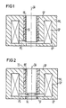
- the electrostatic-magnetic lens shown in Fig. 1 consists of a symmetrical or asymmetrical magnetic lens ML, which is always an electrostatic sion lens is superimposed.
- the magnetic flux generated with the aid of the excitation coil SP is guided over the pole shoes UP and OP and concentrated in a small space around the axis of symmetry OA of the system, the magnetic field being rotationally symmetrical about this axis having its maximum strength in the pole shoe gap PS reached.
- an electrode of the immersion lens is designed in the form of a hollow cylinder RE, which, together with a likewise cylindrical insulator IS, is arranged in the upper pole shoe OP of the magnetic lens ML concentrically with the axis of symmetry OA thereof, and extends into the region of the pole shoe gap PS.
- the lower pole piece of the magnetic lens ML which is preferably at ground potential and, as shown in FIG. 2, can be lined with a beam guiding tube SF made of magnetic or non-magnetic material for protection against contamination, forms the lower electrode of the electrostatic immersion lens according to the invention.
- a rotationally symmetrical electrical delay field builds up inside the magnetic lens ML whenever the cylinder electrode RE is placed at a positive potential with respect to the lower pole shoe UP, in particular at the potential of the anode of the corpuscular beam generator.
- the imaging properties of the corpuscular-optical unit consisting of an electrostatic immersion lens and a magnetic lens are essentially determined by the voltages of the electrodes and their dimensions and the magnetic field strength in the pole shoe gap PS. It is therefore in no way necessary for the cylinder electrode RE and the lower pole shoe opening to have the same diameter.
- the focal length of the electrostatic immersion lens can thus be changed with the aid of a circular pinhole BL, which is arranged inside the cylinder electrode RE or, as shown in FIG. 2, closes in the region of the pole shoe gap PS.
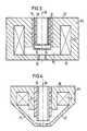
- a continuous change in the focal length is possible if two coaxial cylindrical electrodes RE or SE of different lengths are arranged in the upper pole shoe OP and the external cylinder electrode SE acting as a control electrode is subjected to suitable voltages (see FIG. 3).
- Each of the cylinder electrodes RE or SE can again be closed off by a circular pinhole BL.
- the electrostatic-magnetic lenses according to the invention Due to the electrical delay field superimposed on the focusing magnetic field, the electrostatic-magnetic lenses according to the invention have significantly smaller opening and color error constants than magnetic individual lenses.
- the error constants of the composite system which are essentially determined by the potential difference between cylinder electrode RE and lower pole shoe UP, are reduced by a factor of 10 compared to the error constants of the magnetic single lens, for example, if the corpuscles in the electrical retardation field of the immersion lens are reduced to 1/10 decelerates their primary energy (kinetic energy in the beam path directly above the lens according to the invention).
- the lenses according to the invention also have the advantage that their easily computable corpuscular-optical properties can be implemented very well in practice due to the excellent centerability of the electrical and magnetic lens.
- FIG. 4 An electrostatic-magnetic lens with a conical magnetic lens ML is shown in Fig. 4, in the same Beziers Schweizer same arrangement elements as in Figs. 1 to 3 denote.
- Conical objective lenses are used, for example, in scanning electron microscopes in order to be able to image and examine large-area specimens even in the tilted state with a small working distance. Due to their pole shoe shape, however, conical magnetic lenses have a large gap PS and thus a comparatively long focal length, which leads to relatively large opening and color error constants which increase with the focal length.
- the arrangement according to the invention of a cylindrical electrode RE lying at positive potential in the upper pole shoe OP significantly improves the imaging properties of the corpuscular-optical unit consisting of conical magnetic lens ML and electrostatic immersion lens compared to the conical single lens.
- This improvement in the imaging properties can be achieved by reducing the error constants already described and shifting the main planes of the conical magnetic lens ML towards the sample, which has smaller aberrations due to the associated shortening of the focal length (C F ⁇ focal length).
- the lower pole shoe UP which is preferably at ground potential, again forms an electrode of the electrostatic immersion lens.
- the electrostatic-magnetic lenses according to the invention are advantageously used in scanning particle microscopes, in particular in scanning electron microscopes, in which the Boersch effect limits the resolution, in particular at low acceleration voltages, and conventional lens systems have excessive aberrations. Since the influence of the lateral Boersch effect on the probe diameter decreases at high kinetic energies, the width of the energy distribution of the primary electrons is particularly due to the beam generator of the energetic Boersch effect increases significantly, the electrons should pass through the first beam crossing point (sources crossover) advantageously with low energies (e.g. 2 keV) in order to then accelerate them to high energies (e.g. 10 keV) and only shortly before reaching the sample to the desired low final energy (for example 1 keV).
- sources crossover advantageously with low energies (e.g. 2 keV) in order to then accelerate them to high energies (e.g. 10 keV) and only shortly before reaching the sample to the desired low final energy (for example 1 keV).
- the braking and focusing of the primary electrons is advantageously carried out with the aid of an electrostatic-magnetic lens according to the invention, which replaces one of the conventional condenser lenses or the objective lens in the electron-optical column and whose cylinder electrode RE accelerates the primary electrons at an assumed cathode potential of - 1 kV 10 keV and a desired final energy of the primary electrons from 1 keV to anode potential, that is to 9 kV.
Landscapes
- Chemical & Material Sciences (AREA)
- Analytical Chemistry (AREA)
- Electron Beam Exposure (AREA)
- Eyeglasses (AREA)
- Hard Magnetic Materials (AREA)
- Physical Or Chemical Processes And Apparatus (AREA)
- Treatments Of Macromolecular Shaped Articles (AREA)
Abstract
Eine erfindungsgemäße elektrostatisch-magnetische-Linse besteht aus einer symmetrischen oder unsymmetrischen Magnetlinse (ML), der eine elektrostatische Immersionslinse überlagert ist. Eine Elektrode (RE) der Immersionslinse ist hierbei in Form eines Hohlzylinders ausgebildet, der im oberen Polschuh (OP) der Magnetlinse (ML) konzentrisch zu deren Symmetrieachse (OA) angeordnet wird und sich bis in den Bereich des Polschuhspaltes (SP) erstreckt. Der untere Polschuh (UP) der Magnetlinse (ML), der vorzugsweise auf Erdpotential liegt und zum Schutz gegen Kontamination mit einem Strahlführungsrohr (SF) aus magnetischem oder unmagnetischem Material ausgekleidet sein kann, bildet erfindungsgemäß die untere Elektrode der elektrostatischen Immersionslinse. 
Description
Die Erfindung bezieht sich auf eine elektrostatisch-magnetische-Linse für Korpuskularstrahlgeräte.The invention relates to an electrostatic-magnetic lens for corpuscular beam devices.
In allen Bereichen der Entwicklung und Fertigung mikroelektronischer Bauelemente werden gegenwärtig Korpuskularstrahlgeräte eingesetzt, mit denen man Verfahrensschritte zur Herstellung integrierter Schaltungen kontrolliert, Masken und Wafer inspiziert oder Mikrostrukturen im Rahmen der Elektronenstrahl-Lithografie erzeugt. Besondere Bedeutung haben modifizierte, mit Gegenfeldspektrometern und schnellen Strahlaustastsystemen ausgestattete Raster-Elektronenmikroskope erlangt, mit denen Logik- und Designfehler in hochintegrierten Schaltungen, beispielsweise durch Messung des zeitlichen Spannungsverlaufes an ausgewählten Knotenpunkten, schon während der Entwicklungsphase erkannt und beseitigt werden können. Um Aufladungen und/oder Schädigungen strahlungsempfindlicher Proben zu vermeiden, betreibt man diese Geräte vorwiegend bei niedrigen Beschleunigungsspannungen zwischen etwa 0,5 und 5 kV, wo hochauflösende Untersuchungen mit konventionellen Raster-Elektronenmikroskopen nicht mehr durchführbar sind. In allen Bereichen der Halbleiterindustrie besteht deshalb ein steigender Bedarf an leistungsfähigen Niederspannungs-Rasterelektronenmikroskopen zur Durchführung schneller und hochauflösender Untersuchungen an mikroelektronischen Bauelementen.In all areas of the development and production of microelectronic components, corpuscular beam devices are currently used, with which process steps for the production of integrated circuits are checked, masks and wafers are inspected or microstructures are produced in the context of electron beam lithography. Modified scanning electron microscopes equipped with opposing field spectrometers and fast beam blanking systems, with which logic and design errors in highly integrated circuits, for example by measuring the voltage profile over time at selected nodes, can be recognized and eliminated during the development phase. In order to avoid charging and / or damage to radiation-sensitive samples, these devices are mainly operated at low acceleration voltages between about 0.5 and 5 kV, where high-resolution investigations using conventional scanning electron microscopes can no longer be carried out. In all areas of the semiconductor industry there is therefore an increasing need for high-performance low-voltage scanning electron microscopes to carry out fast and high-resolution investigations on microelectronic components.
Die durch den Strahldurchmesser d auf der Probe vorgegebene Auflösung eines Raster-Elektronenmikroskopes wird bei niedrigen Beschleunigungsspannungen im wesentlichen von der der Fokussierung entgegenwirkenden Coulomb-Abstoßung der Elektronen (Boersch-Effekt) und dem axialen Farbfehler der abbildenden Linsen bestimmt, der nach der unten angegebenen Beziehung mit dem Farbfehlerkoeffizienten CF und bei gleichbleibender Breite der Energieverteilung der Elektronen, mit abnehmender Primärenergie anwächst. Für den die Auflösung bestimmenden Sondendurchmesser d auf der Probe gilt hierbei die bekannte Beziehung
d = (d![]()
![]()
wobei d₀ den um die Coulomb-Abstoßung der Elektronen zwischen Strahlerzeuger und Probe (lateraler Boersch-Effekt) erweiterten geometrisch-optischen Sondendurchmesser und dF den Durchmesser des durch den Farbfehler erzeugten Farbfehlerscheibchens bezeichnet, der über die Beziehung
dF = CF · α · Δ U/U
von der Strahlapertur , dem Farbfehlerkoeffizienten CF der Linse, der Primärenergie eU und der Breite der Energieverteilung e·ΔU der Elektronen abhängt. Eine Verbesserung der Auflösung kann daher nur durch eine Reduktion der nachteiligen Einflüsse der Elektron-Elektron-Wechselwirkung (Reduktion des die Energiebreite eΔU beeinflussenden energetischen Boersch-Effektes und des den Sondendurchmesser beeinflussenden lateralen Boersch-Effektes) und der Farbfehlerkonstanten CF der verwendeten Linsen erreicht werden.The resolution of a scanning electron microscope specified by the beam diameter d on the sample is essentially determined at low acceleration voltages by the Coulomb repulsion of the electrons counteracting the focusing (Boersch effect) and the axial color error of the imaging lenses, according to the relationship given below with the color error coefficient C F and with a constant width of the energy distribution of the electrons, increases with decreasing primary energy. The known relationship applies to the probe diameter d determining the resolution on the sample
d = (d ![]()
![]()
where d₀ is the geometrical-optical probe diameter expanded by the Coulomb repulsion of the electrons between the beam generator and the sample (lateral Boersch effect) and d F denotes the diameter of the color error disk produced by the color error, which is related to the relationship
d F = C F · α · Δ U / U
depends on the beam aperture, the color error coefficient C F of the lens, the primary energy eU and the width of the energy distribution e · ΔU of the electrons. An improvement in the resolution can therefore only be achieved by reducing the adverse effects of the electron-electron interaction (reduction of the energetic Boersch effect influencing the energy width eΔU and the lateral Boersch effect influencing the probe diameter) and the color error constant C F of the lenses used .
Aus der Veröffentlichung von R.F.W. Pease "Low Voltage Scanning Electron Microscopy" (Record of the IEEE 9th Annual Symposium on Electron, Ion and Laser Beam Technology, Berkeley, 9-11 May 1967, Seite 176-187) ist ein Rasterelektronenmikroskop bekannt, in dem die zunächst auf hohe kinetische Energien beschleunigten Primärelektronen in einem unmittelbar oberhalb der Probe aufgebauten elektrischen Gegenfeld auf die gewünschte niedrige Endenergie abgebremst werden. Durch Messung des Strahlquerschnittes auf der Probe konnte man zeigen, daß die Objektivlinse der Anordnung bei Gegenfeldbetrieb deutlich kleinere Farb- und Öffnungsfehlerkonstanten als die magnetische Einzellinse bei konventionellem Betrieb ohne Gegenfeld aufweist.From the publication of RFW Pease "Low Voltage Scanning Electron Microscopy" (Record of the IEEE 9th Annual Symposium on Electron, Ion and Laser Beam Technology, Berkeley, 9-11 May 1967, pages 176-187), a scanning electron microscope is known in which the primary electrons, which were initially accelerated to high kinetic energies, are applied to the electron field in an opposing electric field immediately above the sample desired low final energy are braked. By measuring the beam cross section on the sample, it was possible to show that the objective lens of the arrangement has significantly smaller color and aperture error constants in counter-field operation than the magnetic single lens in conventional operation without an opposing field.
Der Erfindung liegt die Aufgabe zugrunde eine Linse für Korpuskularstrahlgeräte anzugeben, mit der hochenergetische Korpuskeln auf eine gewünschte Endenergie abgebremst werden können und die kleinere Farb- und Öffnungsfehlerkonstanten als konventionelle Magnetlinsen aufweist. Diese Aufgabe wird erfindungsgemäß durch eine elektrostatisch-magnetische-Linse nach Anspruch 1 gelöst.The invention is based on the object of specifying a lens for corpuscular beam devices with which high-energy corpuscles can be braked to a desired final energy and which has smaller color and aperture error constants than conventional magnetic lenses. This object is achieved by an electrostatic-magnetic lens according to claim 1.
Der mit der Erfindung erzielbare Vorteil besteht insbesondere darin, daß auch bei hohen Strahlströmen und niedrigen Beschleunigungsspannungen Korpuskularsonden mit kleinem Strahlquerschnitt erzeugt werden können.The advantage that can be achieved with the invention is, in particular, that corpuscular probes with a small beam cross section can be produced even with high beam currents and low acceleration voltages.
Die Ansprüche 2 bis 10 sind auf bevorzugte Ausgestaltungen und Weiterbildungen der Erfindung gerichtet.Claims 2 to 10 are directed to preferred refinements and developments of the invention.
Die Erfindung wird nachfolgend anhand der Zeichnungen näher erläutert, dabei zeigen die Figuren 1 bis 4 erfindungsgemäße elektrostatisch-magnetische-Linsen.The invention is explained in more detail below with the aid of the drawings, in which FIGS. 1 to 4 show electrostatic-magnetic lenses according to the invention.
Die in Fig. 1 dargestellte elektrostatisch-magnetische-Linse besteht aus einer symmetrischen oder unsymmetrischen Magnetlinse ML, der eine elektrostatische Immer sionslinse überlagert ist. Um möglichst kleine Brennweiten zu erzielen, wird der mit Hilfe der Erregerspule SP erzeugte magnetische Fluß über die Polschuhe UP und OP geführt und auf einen kleinen Raumbereich um die Symmetrieachse OA des Systems konzentriert, wobei das um diese Achse rotationssymmetrische Magnetfeld seine maximale Stärke im Polschuhspalt PS erreicht. Eine Elektrode der Immersionslinse ist in dem gezeigten Ausführungsbeispiel in Form eines Hohlzylinders RE ausgebildet, der zusammen mit einem ebenfalls zylinderförmigen Isolator IS im oberen Polschuh OP der Magnetlinse ML konzentrisch zu deren Symmetrieachse OA angeordnet wird, und sich bis in den Bereich des Polschuhspaltes PS erstreckt. Der untere Polschuh der Magnetlinse ML, der vorzugsweise auf Erdpotential liegt und, wie in Fig. 2 dargestellt, zum Schutz gegen Kontamination mit einem Strahlführungsrohr SF aus magnetischem oder unmagnetischem Material ausgekleidet sein kann, bildet erfindungsgemäß die untere Elektrode der elektrostatischen Immersionslinse. Ein rotationssymmetrisches elektrisches Verzögerungsfeld baut sich innerhalb der Magnetlinse ML immer dann auf, wenn die Zylinderelektrode RE bezüglich des unteren Polschuhes UP auf positives Potential, insbesondere auf das Potential der Anode des Korpuskularstrahlerzeugers gelegt wird.The electrostatic-magnetic lens shown in Fig. 1 consists of a symmetrical or asymmetrical magnetic lens ML, which is always an electrostatic sion lens is superimposed. In order to achieve the smallest possible focal lengths, the magnetic flux generated with the aid of the excitation coil SP is guided over the pole shoes UP and OP and concentrated in a small space around the axis of symmetry OA of the system, the magnetic field being rotationally symmetrical about this axis having its maximum strength in the pole shoe gap PS reached. In the exemplary embodiment shown, an electrode of the immersion lens is designed in the form of a hollow cylinder RE, which, together with a likewise cylindrical insulator IS, is arranged in the upper pole shoe OP of the magnetic lens ML concentrically with the axis of symmetry OA thereof, and extends into the region of the pole shoe gap PS. The lower pole piece of the magnetic lens ML, which is preferably at ground potential and, as shown in FIG. 2, can be lined with a beam guiding tube SF made of magnetic or non-magnetic material for protection against contamination, forms the lower electrode of the electrostatic immersion lens according to the invention. A rotationally symmetrical electrical delay field builds up inside the magnetic lens ML whenever the cylinder electrode RE is placed at a positive potential with respect to the lower pole shoe UP, in particular at the potential of the anode of the corpuscular beam generator.
Die Abbildungseigenschaften der aus elektrostatischer Immersionslinse und Magnetlinse bestehenden korpuskular-optischen Einheit werden im wesentlichen von den Spannungen der Elektroden und deren Abmessungen und der Magnetfeldstärke im Polschuhspalt PS bestimmt. Es ist deshalb keineswegs erforderlich, daß die Zylinderelektrode RE und die untere Polschuhöffnung gleichen Durchmesser aufweisen.The imaging properties of the corpuscular-optical unit consisting of an electrostatic immersion lens and a magnetic lens are essentially determined by the voltages of the electrodes and their dimensions and the magnetic field strength in the pole shoe gap PS. It is therefore in no way necessary for the cylinder electrode RE and the lower pole shoe opening to have the same diameter.
Die Lage der Zylinderelektrode RE innerhalb der Magnetlinse ML, ihr Durchmesser und ihr Abstand vom unteren Polschuh UP müssen vielmehr den geforderten korpuskular-optischen Eigenschaften des Gesamtsystems angepaßt werden. So läßt sich die Brennweite der elektrostatischen Immersionslinse mit Hilfe einer kreisförmigen Lochblende BL verändern, die innerhalb der Zylinderelektrode RE angeordnet wird oder diese, wie in Fig. 2 dargestellt, im Bereich des Polschuhspaltes PS abschließt. Eine kontinuierliche Veränderung der Brennweite ist möglich, wenn man zwei koaxial liegende Zylinderelektroden RE bzw. SE unterschiedlicher Länge im oberen Polschuhes OP anordnet und die als Steuerelektrode wirkende äußere Zylinderelektrode SE mit geeigneten Spannungen beaufschlagt (siehe Fig. 3). Jede der Zylinderelektroden RE bzw. SE kann hierbei wieder von einer kreisförmigen Lochblende BL abgeschlossen werden.The position of the cylinder electrode RE within the magnetic lens ML, its diameter and its distance from the lower one Pole shoe UP must rather be adapted to the required corpuscular-optical properties of the overall system. The focal length of the electrostatic immersion lens can thus be changed with the aid of a circular pinhole BL, which is arranged inside the cylinder electrode RE or, as shown in FIG. 2, closes in the region of the pole shoe gap PS. A continuous change in the focal length is possible if two coaxial cylindrical electrodes RE or SE of different lengths are arranged in the upper pole shoe OP and the external cylinder electrode SE acting as a control electrode is subjected to suitable voltages (see FIG. 3). Each of the cylinder electrodes RE or SE can again be closed off by a circular pinhole BL.
Die erfindungsgemäßen elektrostatisch-magnetischen-Linsen besitzen aufgrund des dem fokussierenden Magnetfeld überlagerten elektrischen Verzögerungsfeldes deutlich kleinere Öffnungs- und Farbfehlerkonstanten als magnetische Einzellinsen. So werden die im wesentlichen von der Potentialdifferenz zwischen Zylinderelektrode RE und unterem Polschuh UP bestimmten Fehlerkonstanten des zusammengesetzten Systems, verglichen mit den Fehlerkonstanten der magnetischen Einzellinse beispielsweise, um etwa einen Faktor 10 reduziert, wenn man die Korpuskeln im elektrischen Verzögerungsfeld der Immersionslinse auf 1/10 ihrer Primärenergie (kinetische Energie im Strahlengang unmittelbar oberhalb der erfindungsgemäßen Linse) abbremst. Die erfindungsgemäßen Linsen besitzen außerdem den Vorteil, daß sich deren leicht berechenbare korpuskular-optische Eigenschaften aufgrund der ausgezeichneten Zentrierbarkeit von elektrischer und magnetischer Linse sehr gut in der Praxis realisieren lassen.Due to the electrical delay field superimposed on the focusing magnetic field, the electrostatic-magnetic lenses according to the invention have significantly smaller opening and color error constants than magnetic individual lenses. For example, the error constants of the composite system, which are essentially determined by the potential difference between cylinder electrode RE and lower pole shoe UP, are reduced by a factor of 10 compared to the error constants of the magnetic single lens, for example, if the corpuscles in the electrical retardation field of the immersion lens are reduced to 1/10 decelerates their primary energy (kinetic energy in the beam path directly above the lens according to the invention). The lenses according to the invention also have the advantage that their easily computable corpuscular-optical properties can be implemented very well in practice due to the excellent centerability of the electrical and magnetic lens.
Eine elektrostatisch-magnetische-Linse mit konischer Magnetlinse ML ist in Fig. 4 dargestellt, in der gleiche Be zugszeichen gleiche Anordnungselemente wie in den Fig. 1 bis 3 bezeichnen. Konische Objektivlinsen werden beispielsweise in Rasterelektronenmikroskopen eingesetzt, um großflächige Präparate auch in gekipptem Zustand bei kleinem Arbeitsabstand abbilden und untersuchen zu können. Aufgrund ihrer Polschuhform besitzen konische Magnetlinsen allerdings einen großen Spalt PS und damit eine Vergleichsweise lange Brennweite, was zu relativ großen, mit der Brennweite anwachsenden Öffnungs- und Farbfehlerkonstanten führt. Durch die erfindungsgemäße Anordnung einer auf positiven Potential liegenden zylinderförmigen Elektrode RE im oberen Polschuhe OP, werden die Abbildungseigenschaften des aus konischer Magnetlinse ML und elektrostatischer Immersionslinse bestehenden korpuskularoptischen Einheit gegenüber der konischen Einzellinse deutlich verbessert. Diese Verbesserung der Abbildungseigenschaften erreicht man durch die schon beschriebene Verringerung der Fehlerkonstanten und eine Verschiebung der Hauptebenen der konischen Magnetlinse ML in Richtung der Probe, die aufgrund der damit einhergehenden Verkürzung der Brennweite kleinere Aberrationen aufweist (CF ∼ Brennweite). Auch in diesem Ausführungsbeispiel bildet der vorzugsweise auf Erdpotential liegende untere Polschuh UP wieder eine Elektrode der elektrostatischen Immersionslinse.An electrostatic-magnetic lens with a conical magnetic lens ML is shown in Fig. 4, in the same Be Zugszeichen same arrangement elements as in Figs. 1 to 3 denote. Conical objective lenses are used, for example, in scanning electron microscopes in order to be able to image and examine large-area specimens even in the tilted state with a small working distance. Due to their pole shoe shape, however, conical magnetic lenses have a large gap PS and thus a comparatively long focal length, which leads to relatively large opening and color error constants which increase with the focal length. The arrangement according to the invention of a cylindrical electrode RE lying at positive potential in the upper pole shoe OP significantly improves the imaging properties of the corpuscular-optical unit consisting of conical magnetic lens ML and electrostatic immersion lens compared to the conical single lens. This improvement in the imaging properties can be achieved by reducing the error constants already described and shifting the main planes of the conical magnetic lens ML towards the sample, which has smaller aberrations due to the associated shortening of the focal length (C F ∼ focal length). In this exemplary embodiment, too, the lower pole shoe UP, which is preferably at ground potential, again forms an electrode of the electrostatic immersion lens.
Die erfindungsgemäßen elektrostatisch-magnetischen-Linsen werden vorteilhafterweise in Raster-Korpuskularmikroskopen, insbesondere in Raster-Elektronenmikroskopen eingesetzt, in denen der Boersch-Effekt die Auflösung insbesondere bei niedrigen Beschleunigungsspannungen begrenzt und konventionelle Linsensysteme zu große Aberrationen aufweisen. Da der Einfluß des lateralen Boersch-Effektes auf den Sondendurchmesser bei hohen kinetischen Energien abnimmt, die Breite der Energieverteilung der Primärelektronen insbesondere im Strahlerzeuger infolge des energetischen Boersch-Effektes aber deutlich zunimmt, sollten die Elektronen den ersten Strahlüberkreuzungspunkt (Quellen crossover) vorteilhafterweise mit niedrigen Energien (beispielsweise 2 keV) durchlaufen, um sie anschließend auf hohe Energien (beispielsweise 10 keV) zu beschleunigen und erst kurz vor Erreichen der Probe auf die gewünschte niedrige Endenergie (beispielsweise 1 keV) abzubremsen. Die Abbremsung und Fokussierung der Primärelektronen erfolgt hierbei vorteilhafterweise mit Hilfe einer erfindungsgemäßen elektrostatisch-magnetischen-Linse, die eine der konventionellen Kondensorlinsen oder die Objektivlinse in der elektronenoptischen Säule ersetzt und deren Zylinderelektrode RE bei einem angenommenen Kathodenpotential von - 1 kV, einer Beschleunigung der Primärelektronen auf 10 keV und einer gewünschten Endenergie der Primärelektronen von 1 keV auf Anodenpotential, also auf 9 kV liegt.The electrostatic-magnetic lenses according to the invention are advantageously used in scanning particle microscopes, in particular in scanning electron microscopes, in which the Boersch effect limits the resolution, in particular at low acceleration voltages, and conventional lens systems have excessive aberrations. Since the influence of the lateral Boersch effect on the probe diameter decreases at high kinetic energies, the width of the energy distribution of the primary electrons is particularly due to the beam generator of the energetic Boersch effect increases significantly, the electrons should pass through the first beam crossing point (sources crossover) advantageously with low energies (e.g. 2 keV) in order to then accelerate them to high energies (e.g. 10 keV) and only shortly before reaching the sample to the desired low final energy (for example 1 keV). The braking and focusing of the primary electrons is advantageously carried out with the aid of an electrostatic-magnetic lens according to the invention, which replaces one of the conventional condenser lenses or the objective lens in the electron-optical column and whose cylinder electrode RE accelerates the primary electrons at an assumed cathode potential of - 1 kV 10 keV and a desired final energy of the primary electrons from 1 keV to anode potential, that is to 9 kV.
BL Blende
IS Isolator
ML Magnetlinse
OA Symmetrieachse der Magnetlinse
OP oberer Polschuh der Magnetlinse
PS Polschuhspalt
RE Zylinderelektrode
SE hohlzylinderförmige Elektrode
SF Strahlführungsrohr
UP unterer Polschuh der Magnetlinse
BL aperture
IS isolator
ML magnetic lens
OA axis of symmetry of the magnetic lens
OP upper pole piece of the magnetic lens
PS pole shoe gap
RE cylinder electrode
SE hollow cylindrical electrode
SF beam guide tube
UP lower pole piece of the magnetic lens
Claims (10)
Priority Applications (1)
| Application Number | Priority Date | Filing Date | Title |
|---|---|---|---|
| AT87104111T ATE91822T1 (en) | 1986-04-24 | 1987-03-20 | ELECTROSTATIC-MAGNETIC LENS FOR CORPUSCULAR BLASTING DEVICES. |
Applications Claiming Priority (2)
| Application Number | Priority Date | Filing Date | Title |
|---|---|---|---|
| DE3613915 | 1986-04-24 | ||
| DE3613915 | 1986-04-24 |
Publications (3)
| Publication Number | Publication Date |
|---|---|
| EP0242602A2 true EP0242602A2 (en) | 1987-10-28 |
| EP0242602A3 EP0242602A3 (en) | 1989-09-06 |
| EP0242602B1 EP0242602B1 (en) | 1993-07-21 |
Family
ID=6299463
Family Applications (1)
| Application Number | Title | Priority Date | Filing Date |
|---|---|---|---|
| EP87104111A Expired - Lifetime EP0242602B1 (en) | 1986-04-24 | 1987-03-20 | Electrostatic and magnetic lens for corpuscular beam apparatus |
Country Status (6)
| Country | Link |
|---|---|
| US (1) | US4785176A (en) |
| EP (1) | EP0242602B1 (en) |
| JP (1) | JPH0624106B2 (en) |
| AT (1) | ATE91822T1 (en) |
| CA (1) | CA1264873A (en) |
| DE (1) | DE3786588D1 (en) |
Cited By (2)
| Publication number | Priority date | Publication date | Assignee | Title |
|---|---|---|---|---|
| EP0790634A1 (en) * | 1996-02-16 | 1997-08-20 | ACT Advanced Circuit Testing Gesellschaft für Testsystementwicklung mbH | Electrostatic-magnetic lens arrangement |
| US6949744B2 (en) | 2003-04-17 | 2005-09-27 | Carl Zeiss Nts Gmbh | Electron microscopy system, electron microscopy method and focusing system for charged particles |
Families Citing this family (38)
| Publication number | Priority date | Publication date | Assignee | Title |
|---|---|---|---|---|
| DE3766092D1 (en) * | 1986-12-12 | 1990-12-13 | Integrated Circuit Testing | DETECTOR ARRANGEMENT WITH A DETECTOR LENS FOR BODY RADIATORS. |
| KR920000941B1 (en) * | 1988-02-16 | 1992-01-31 | 후지쓰 가부시끼가이샤 | Electron Beam Exposure Equipment |
| US4926054A (en) * | 1988-03-17 | 1990-05-15 | Ict Integrated Circuit Testing Gesellschaft Fur Halbleiterpruftechnik Mbh | Objective lens for focusing charged particles in an electron microscope |
| JP2882412B2 (en) | 1989-01-20 | 1999-04-12 | 富士通株式会社 | Electron beam exposure equipment |
| US5041731A (en) * | 1989-01-20 | 1991-08-20 | Fujitsu Limited | Deflection compensating device for converging lens |
| DE68917310T2 (en) * | 1989-12-13 | 1995-03-09 | Ibm | Delta-phi microlens for low energy particle beams. |
| JPH071681B2 (en) * | 1990-04-19 | 1995-01-11 | 株式会社日立製作所 | Charged particle beam device |
| US5146090A (en) * | 1990-06-11 | 1992-09-08 | Siemens Aktiengesellschaft | Particle beam apparatus having an immersion lens arranged in an intermediate image of the beam |
| JP2777840B2 (en) * | 1990-11-30 | 1998-07-23 | セイコーインスツルメンツ株式会社 | Electron beam equipment |
| US5629526A (en) * | 1993-09-28 | 1997-05-13 | Nikon Corporation | Electro-magnetic lens, charged particle beam transferring apparatus, and method for manufacturing electro-magnetic lens |
| DE69512410T2 (en) * | 1994-04-12 | 2000-05-04 | Koninklijke Philips Electronics N.V., Eindhoven | Particle optical device with a secondary electrode detector |
| US5644132A (en) * | 1994-06-20 | 1997-07-01 | Opan Technologies Ltd. | System for high resolution imaging and measurement of topographic and material features on a specimen |
| US5614833A (en) * | 1994-10-25 | 1997-03-25 | International Business Machines Corporation | Objective lens with large field deflection system and homogeneous large area secondary electron extraction field |
| DE4438315A1 (en) * | 1994-10-26 | 1996-05-02 | Siemens Ag | Gas ion removal device from electron beam in tomography appts. |
| DE69638126D1 (en) * | 1995-10-19 | 2010-04-01 | Hitachi Ltd | scanning Electron Microscope |
| JPH09147779A (en) * | 1995-11-20 | 1997-06-06 | Nikon Corp | Electromagnetic deflector |
| US5780859A (en) * | 1996-02-16 | 1998-07-14 | Act Advanced Circuit Testing Gesellschaft | Electrostatic-magnetic lens arrangement |
| JP3580060B2 (en) * | 1996-05-09 | 2004-10-20 | 富士ゼロックス株式会社 | Print control apparatus and method |
| DE19732093B4 (en) * | 1997-07-25 | 2008-09-25 | Carl Zeiss Nts Gmbh | Charged particle beam |
| US6069363A (en) * | 1998-02-26 | 2000-05-30 | International Business Machines Corporation | Magnetic-electrostatic symmetric doublet projection lens |
| WO2001045136A1 (en) * | 1999-12-14 | 2001-06-21 | Applied Materials, Inc. | Method and system for the examination of specimen using a charged particle beam |
| US6392231B1 (en) | 2000-02-25 | 2002-05-21 | Hermes-Microvision, Inc. | Swinging objective retarding immersion lens electron optics focusing, deflection and signal collection system and method |
| US6960766B2 (en) * | 2000-02-25 | 2005-11-01 | Hermes-Microvision, Inc. | Swinging objective retarding immersion lens electron optics focusing, deflection and signal collection system and method |
| US7800062B2 (en) * | 2002-06-11 | 2010-09-21 | Applied Materials, Inc. | Method and system for the examination of specimen |
| DE10237297A1 (en) * | 2002-08-14 | 2004-03-11 | Leo Elektronenmikroskopie Gmbh | Optical apparatus e.g. scanning electron microscope has controller which applies different excitation patterns to row of field source elements of lens assemblies |
| DE60323909D1 (en) * | 2002-08-13 | 2008-11-20 | Zeiss Carl Nts Gmbh | Particle-optic apparatus and its use as an electron-microscopic system |
| US7528614B2 (en) | 2004-12-22 | 2009-05-05 | Applied Materials, Inc. | Apparatus and method for voltage contrast analysis of a wafer using a tilted pre-charging beam |
| NL1023260C1 (en) * | 2003-04-24 | 2004-10-27 | Fei Co | Particle-optical device with a permanent magnetic lens and an electrostatic lens. |
| EP1777728A1 (en) * | 2005-10-20 | 2007-04-25 | Carl Zeiss SMS GmbH | Lithography system |
| KR101384260B1 (en) * | 2005-12-05 | 2014-04-11 | 전자빔기술센터 주식회사 | Method for focusing electron beam in electron column |
| DE102007010873B4 (en) | 2007-03-06 | 2009-07-30 | Carl Zeiss Nts Gmbh | objective lens |
| JP4977509B2 (en) * | 2007-03-26 | 2012-07-18 | 株式会社日立ハイテクノロジーズ | Scanning electron microscope |
| US8319192B2 (en) | 2010-08-24 | 2012-11-27 | Hermes Microvision Inc. | Charged particle apparatus |
| US9922796B1 (en) * | 2016-12-01 | 2018-03-20 | Applied Materials Israel Ltd. | Method for inspecting a specimen and charged particle multi-beam device |
| US10777382B2 (en) | 2017-11-21 | 2020-09-15 | Focus-Ebeam Technology (Beijing) Co., Ltd. | Low voltage scanning electron microscope and method for specimen observation |
| US10504684B1 (en) * | 2018-07-12 | 2019-12-10 | ICT Integrated Circuit Testing Gesellschaft für Halbleiterprüftechnik mbH | High performance inspection scanning electron microscope device and method of operating the same |
| CN114256043B (en) | 2020-12-02 | 2024-04-05 | 聚束科技(北京)有限公司 | An electron beam system |
| CN114220725B (en) | 2020-12-02 | 2024-05-07 | 聚束科技(北京)有限公司 | Electron microscope |
Family Cites Families (6)
| Publication number | Priority date | Publication date | Assignee | Title |
|---|---|---|---|---|
| DE1012398B (en) * | 1943-11-27 | 1957-07-18 | Dr Heinrich Herbst | Electron-optical lens system for electron or ion microscopes |
| NL177578C (en) * | 1976-05-14 | 1985-10-16 | Thomson Csf | DEVICE FOR DESCRIBING AN OBJECT WITH A PARTICULAR BUNDLE. |
| JPS57118357A (en) * | 1981-01-14 | 1982-07-23 | Jeol Ltd | Objective lens for scan type electron microscope |
| DE3138992A1 (en) * | 1981-09-30 | 1983-04-14 | Siemens AG, 1000 Berlin und 8000 München | SCANING PROCESS FOR FAST DETERMINATION OF POTENTIAL IN ELECTRON BEAM MEASUREMENT TECHNOLOGY |
| GB2115976A (en) * | 1982-02-26 | 1983-09-14 | Philips Electronic Associated | Charged particle beam apparatus |
| US4713543A (en) * | 1984-08-13 | 1987-12-15 | Siemens Aktiengesellschaft | Scanning particle microscope |
-
1987
- 1987-03-20 DE DE8787104111T patent/DE3786588D1/en not_active Expired - Lifetime
- 1987-03-20 AT AT87104111T patent/ATE91822T1/en not_active IP Right Cessation
- 1987-03-20 EP EP87104111A patent/EP0242602B1/en not_active Expired - Lifetime
- 1987-03-27 US US07/030,964 patent/US4785176A/en not_active Expired - Lifetime
- 1987-04-20 JP JP62097253A patent/JPH0624106B2/en not_active Expired - Fee Related
- 1987-04-22 CA CA000535238A patent/CA1264873A/en not_active Expired - Lifetime
Cited By (2)
| Publication number | Priority date | Publication date | Assignee | Title |
|---|---|---|---|---|
| EP0790634A1 (en) * | 1996-02-16 | 1997-08-20 | ACT Advanced Circuit Testing Gesellschaft für Testsystementwicklung mbH | Electrostatic-magnetic lens arrangement |
| US6949744B2 (en) | 2003-04-17 | 2005-09-27 | Carl Zeiss Nts Gmbh | Electron microscopy system, electron microscopy method and focusing system for charged particles |
Also Published As
| Publication number | Publication date |
|---|---|
| JPH0624106B2 (en) | 1994-03-30 |
| EP0242602B1 (en) | 1993-07-21 |
| JPS62256352A (en) | 1987-11-09 |
| CA1264873A (en) | 1990-01-23 |
| DE3786588D1 (en) | 1993-08-26 |
| US4785176A (en) | 1988-11-15 |
| EP0242602A3 (en) | 1989-09-06 |
| ATE91822T1 (en) | 1993-08-15 |
Similar Documents
| Publication | Publication Date | Title |
|---|---|---|
| EP0242602B1 (en) | Electrostatic and magnetic lens for corpuscular beam apparatus | |
| EP0461442B1 (en) | Particle beam apparatus | |
| EP0333018B1 (en) | Objective lens for focusing charged particles | |
| EP0274622B1 (en) | Detector assembly with detector objective for corpuscular ray instruments | |
| EP0281743B1 (en) | Detector objective for a scanning microscope | |
| DE10233002B4 (en) | Objective lens for an electron microscopy system and electron microscopy system | |
| EP0267555B1 (en) | Spectrometer objective for a corpuscular beam measuring apparatus and method for examining samples. | |
| EP1220292B1 (en) | Monochromator for charged particles | |
| EP0180723B1 (en) | Corpuscular beam device | |
| EP0205184B1 (en) | Low aberration spectrometer objective with a high secondary electrons acceptance | |
| DE3841715A1 (en) | IMAGING CORRECTOR VIENNA TYPE FOR ELECTRONIC MICROSCOPE | |
| EP0893816A2 (en) | Corpuscular beam apparatus | |
| EP0194570A2 (en) | Scanning corpuscular microscope with reduced Boersch effect | |
| DE112015001235B4 (en) | DEVICE AND METHOD FOR ELECTRON BEAM IMAGING USING A MONOCHROMATOR WITH DOUBLE WIEN FILTER AND MONOCHROMATOR | |
| DE10056482A1 (en) | Semiconductor industry ionic beam former having particle source filter passed reduced energy offsets and dispensing unwanted energy field. | |
| DE102019107327A1 (en) | Apparatus and method for electron transfer from a sample to an energy analyzer and electron spectrometer apparatus | |
| DE60105199T2 (en) | SEM WITH A SECONDARY ELECTRODE DETECTOR WITH A CENTRAL ELECTRODE | |
| EP0910109B1 (en) | Objective lens | |
| EP0205185B1 (en) | Objective with spectrometer in the electron beam measuring technique | |
| EP0910108B1 (en) | Electron beam lens | |
| DE102023106030A1 (en) | Electron beam microscope | |
| EP0236807A2 (en) | Spectrometer objective for the corpuscular beam measuring technique | |
| DE19746785A1 (en) | Particle beam device with energy filter | |
| DE3703028A1 (en) | GRID MICROSCOPE | |
| DE102015210893B4 (en) | Analysis device for analyzing the charged particle energy and particle beam device with an analysis device |
Legal Events
| Date | Code | Title | Description |
|---|---|---|---|
| PUAI | Public reference made under article 153(3) epc to a published international application that has entered the european phase |
Free format text: ORIGINAL CODE: 0009012 |
|
| AK | Designated contracting states |
Kind code of ref document: A2 Designated state(s): AT CH DE FR GB IT LI NL SE |
|
| PUAL | Search report despatched |
Free format text: ORIGINAL CODE: 0009013 |
|
| AK | Designated contracting states |
Kind code of ref document: A3 Designated state(s): AT CH DE FR GB IT LI NL SE |
|
| RAP1 | Party data changed (applicant data changed or rights of an application transferred) |
Owner name: ICT INTEGRATED CIRCUIT TESTING GESELLSCHAFT FUER H |
|
| 17P | Request for examination filed |
Effective date: 19900220 |
|
| 17Q | First examination report despatched |
Effective date: 19920630 |
|
| GRAA | (expected) grant |
Free format text: ORIGINAL CODE: 0009210 |
|
| AK | Designated contracting states |
Kind code of ref document: B1 Designated state(s): AT CH DE FR GB IT LI NL SE |
|
| REF | Corresponds to: |
Ref document number: 91822 Country of ref document: AT Date of ref document: 19930815 Kind code of ref document: T |
|
| ITF | It: translation for a ep patent filed | ||
| REF | Corresponds to: |
Ref document number: 3786588 Country of ref document: DE Date of ref document: 19930826 |
|
| GBT | Gb: translation of ep patent filed (gb section 77(6)(a)/1977) |
Effective date: 19930816 |
|
| ET | Fr: translation filed | ||
| PG25 | Lapsed in a contracting state [announced via postgrant information from national office to epo] |
Ref country code: AT Effective date: 19940320 |
|
| PG25 | Lapsed in a contracting state [announced via postgrant information from national office to epo] |
Ref country code: SE Free format text: LAPSE BECAUSE OF NON-PAYMENT OF DUE FEES Effective date: 19940321 |
|
| PG25 | Lapsed in a contracting state [announced via postgrant information from national office to epo] |
Ref country code: CH Effective date: 19940331 Ref country code: LI Effective date: 19940331 |
|
| PLBE | No opposition filed within time limit |
Free format text: ORIGINAL CODE: 0009261 |
|
| STAA | Information on the status of an ep patent application or granted ep patent |
Free format text: STATUS: NO OPPOSITION FILED WITHIN TIME LIMIT |
|
| 26N | No opposition filed | ||
| REG | Reference to a national code |
Ref country code: CH Ref legal event code: PL |
|
| EUG | Se: european patent has lapsed |
Ref document number: 87104111.7 Effective date: 19941010 |
|
| REG | Reference to a national code |
Ref country code: FR Ref legal event code: TP |
|
| REG | Reference to a national code |
Ref country code: GB Ref legal event code: 732E |
|
| REG | Reference to a national code |
Ref country code: GB Ref legal event code: 732E |
|
| NLS | Nl: assignments of ep-patents |
Owner name: ADVANTEST CORPORATION;ACT ADVANCED CIRCUIT TESTING |
|
| REG | Reference to a national code |
Ref country code: FR Ref legal event code: TP |
|
| REG | Reference to a national code |
Ref country code: GB Ref legal event code: 732E |
|
| NLS | Nl: assignments of ep-patents |
Owner name: ADVANTEST CORPORATION |
|
| REG | Reference to a national code |
Ref country code: FR Ref legal event code: TP |
|
| REG | Reference to a national code |
Ref country code: GB Ref legal event code: IF02 |
|
| PG25 | Lapsed in a contracting state [announced via postgrant information from national office to epo] |
Ref country code: IT Free format text: LAPSE BECAUSE OF NON-PAYMENT OF DUE FEES;WARNING: LAPSES OF ITALIAN PATENTS WITH EFFECTIVE DATE BEFORE 2007 MAY HAVE OCCURRED AT ANY TIME BEFORE 2007. THE CORRECT EFFECTIVE DATE MAY BE DIFFERENT FROM THE ONE RECORDED. Effective date: 20050320 |
|
| PGFP | Annual fee paid to national office [announced via postgrant information from national office to epo] |
Ref country code: FR Payment date: 20060209 Year of fee payment: 20 |
|
| PGFP | Annual fee paid to national office [announced via postgrant information from national office to epo] |
Ref country code: GB Payment date: 20060213 Year of fee payment: 20 |
|
| PGFP | Annual fee paid to national office [announced via postgrant information from national office to epo] |
Ref country code: NL Payment date: 20060215 Year of fee payment: 20 |
|
| PGFP | Annual fee paid to national office [announced via postgrant information from national office to epo] |
Ref country code: DE Payment date: 20060526 Year of fee payment: 20 |
|
| PG25 | Lapsed in a contracting state [announced via postgrant information from national office to epo] |
Ref country code: GB Free format text: LAPSE BECAUSE OF EXPIRATION OF PROTECTION Effective date: 20070319 |
|
| PG25 | Lapsed in a contracting state [announced via postgrant information from national office to epo] |
Ref country code: NL Free format text: LAPSE BECAUSE OF EXPIRATION OF PROTECTION Effective date: 20070320 |
|
| REG | Reference to a national code |
Ref country code: GB Ref legal event code: PE20 |
|
| NLV7 | Nl: ceased due to reaching the maximum lifetime of a patent |
Effective date: 20070320 |