EP0910108B1 - Electron beam lens - Google Patents
Electron beam lens Download PDFInfo
- Publication number
- EP0910108B1 EP0910108B1 EP97116909A EP97116909A EP0910108B1 EP 0910108 B1 EP0910108 B1 EP 0910108B1 EP 97116909 A EP97116909 A EP 97116909A EP 97116909 A EP97116909 A EP 97116909A EP 0910108 B1 EP0910108 B1 EP 0910108B1
- Authority
- EP
- European Patent Office
- Prior art keywords
- lens
- electron beam
- pole piece
- pole
- lens according
- Prior art date
- Legal status (The legal status is an assumption and is not a legal conclusion. Google has not performed a legal analysis and makes no representation as to the accuracy of the status listed.)
- Expired - Lifetime
Links
- 238000010894 electron beam technology Methods 0.000 title claims description 59
- 238000000605 extraction Methods 0.000 claims description 2
- 230000000979 retarding effect Effects 0.000 claims 1
- 239000011163 secondary particle Substances 0.000 claims 1
- 241000219739 Lens Species 0.000 description 73
- 230000003287 optical effect Effects 0.000 description 10
- 239000000523 sample Substances 0.000 description 9
- 230000000694 effects Effects 0.000 description 3
- 240000004322 Lens culinaris Species 0.000 description 2
- 230000015572 biosynthetic process Effects 0.000 description 2
- 230000005405 multipole Effects 0.000 description 2
- 230000005684 electric field Effects 0.000 description 1
- 230000003116 impacting effect Effects 0.000 description 1
Images


Classifications
-
- H—ELECTRICITY
- H01—ELECTRIC ELEMENTS
- H01J—ELECTRIC DISCHARGE TUBES OR DISCHARGE LAMPS
- H01J37/00—Discharge tubes with provision for introducing objects or material to be exposed to the discharge, e.g. for the purpose of examination or processing thereof
- H01J37/02—Details
- H01J37/04—Arrangements of electrodes and associated parts for generating or controlling the discharge, e.g. electron-optical arrangement, ion-optical arrangement
- H01J37/10—Lenses
- H01J37/145—Combinations of electrostatic and magnetic lenses
-
- H—ELECTRICITY
- H01—ELECTRIC ELEMENTS
- H01J—ELECTRIC DISCHARGE TUBES OR DISCHARGE LAMPS
- H01J37/00—Discharge tubes with provision for introducing objects or material to be exposed to the discharge, e.g. for the purpose of examination or processing thereof
- H01J37/02—Details
- H01J37/04—Arrangements of electrodes and associated parts for generating or controlling the discharge, e.g. electron-optical arrangement, ion-optical arrangement
- H01J37/10—Lenses
- H01J37/14—Lenses magnetic
- H01J37/141—Electromagnetic lenses
Definitions
- the invention relates to an electron beam lens, containing a magnetic lens to influence a Electron beam with a first and a second Pole shoe, with a magnetic field between the two Forms pole pieces and also a third pole piece is provided.
- the invention further relates to a cathode lens and an electron beam device with such an electron beam lens.
- a magnetic lens Influencing an electron beam known to be an upper one and has a lower pole piece and a third pole piece which is placed between the other two pole pieces and is not in magnetic contact with them.
- a multipole lens is known from EP-A-0 133 016, which essentially consists of a series of there are two bipolar lenses of the type described above.
- the electron beam lens according to the preamble of claim 1 in their optical properties for the primary beam and in their Collection properties for the secondary rays further to improve.
- the electron beam lens is characterized in that the third pole piece in the between the first and second pole shoe trained magnetic field immersed and thereby decouples part of this magnetic field, being the decoupled part of the main magnetic field at the bottom Forms a secondary field at the end of the third pole piece.
- the decoupled part of the (main) magnetic field forms a second lens field at the lower end of the third pole piece (Secondary field).
- the secondary field has on the one hand a focusing effect on the primary beam and good optical properties due to its proximity to the sample and on the other hand prevents the secondary rays from moving expand.
- the secondary beam can therefore enter the lens system "bundled" and from one Spectrometer / detector arrangement or a detector in or above the lens with high efficiency be detected.
- the Electron beam lens advantageous in a cathode lens used By that generated by the third pole piece Secondary field ensures that this is positive bring the impacting magnetic field close to the cathode leaves without the need for a large physical lens is. Thanks to the suitable design of the three-pole magnetic lens can the strength of the secondary field on the Cathode tip and the optical properties of the as Condenser acting first and second pole pieces separately optimize.
- the electron beam lens in an electron beam device used.
- the Samples are tilted with respect to the primary beam.
- the special design of the electron beam lens enables if the working distance is short, a strong tilting or offers space for other optional elements such as detectors, Manipulators etc.
- the electron beam lens shown in Fig.1a has a magnetic lens 1 for influencing an electron beam with a first, inner pole piece 10 and a second, outer pole piece 11.
- the first and second Pole shoe 10, 11 are in the illustrated embodiment as a two-pole lens with a conical outer Pole shoe 11 and a coil 15 shown, wherein there is a magnetic between the first and second pole pieces Main field 12 trains.
- the magnetic lens 1 also has a third pole piece 13 that is not in magnetic contact with the The other two pole pieces stand between the two first and second pole shoe 10, 11 formed magnetic field dips.
- the third pole piece 13 is preferred cylindrical and dips into the main field 12 that part of this magnetic field is coupled out becomes.
- 1b shows the spread of the main field 12 and of the secondary field 14 shown.
- the strenght the secondary field 14 depends on how far the third Pole shoe 13 dips into the main field and a corresponding one Share of the magnetic field and how large the gap to the inner or outer pole piece 10, 11th is.
- the third pole piece 13 expediently in relation to the first and second pole pieces 10, 11 slidably or arranged adjustable.
- the maxima of the axial magnetic fields of the main and secondary fields are designated B 1 and B 2 .
- the third pole piece is preferably arranged in relation to the first and second pole pieces such that the amplitude B 2 of the secondary field is at least 15%, preferably between 20% and 60% of the amplitude B 1 of the main field.
- Magnetic three-pole lens shows a conventional Fig. 2a Two-pole lens with a first and second pole 10, 11. Accordingly, only a magnetic field is formed 12, whose distribution is shown in Fig.2b is.
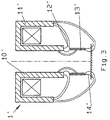
- FIG. 3 shows a second exemplary embodiment according to the invention an electron beam lens that differs from the 1a differs only in that that by a first pole piece 10 ' and formed by a second pole piece 11 ' Magnet lens 1 'is designed as a single-pole lens.
- a main and a secondary field are formed 12 ', 14'.
- the advantage of using a single pole lens in combination with a third pole piece 13 ' is mainly that with the single pole lens generates a particularly strong magnetic field and accordingly also a strong part passed on as secondary field 14 ' can be.
- the two electron beam lenses shown in Figures 1a and 3 can also be advantageous with a electrostatic lens, especially an electrostatic Combine brake lens.
- the electrostatic Lens consists of at least a first and a second, with different potentials Electrode.
- 1a is an example of an electrostatic Shown lens 2
- the first electrode consists of a jet pipe 20 which is coaxial to first pole piece 10 arranged inside the magnetic lens 1 is.
- the second electrode is replaced by the third Pole shoe 13 formed.
- the jet pipe 20 for example has high positive potential a suitable, lower one on the third pole piece 13 Apply positive or negative voltage U to the desired braking effect on the electron beam produce.
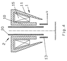
- the jet pipe 20 is wider pulled down so that it is in the third pole piece 13 dips.
- the electrostatic lens forms in this case in the area of the submerged end of the first Electrode 20 and the adjacent wall of the third pole piece 13.
- the second Electrode of the electrostatic lens 2 not through the third pole piece 13, but by a separate, in the pole shoe 13 inserted tube electrode 21 is formed.
- this tube electrode 21 transversely to the optical axis 16 or is interrupted several times in order to electrostatic lens through at least three electrodes build.
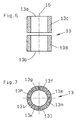
- Fig. 6 shows an alternative way of building the electrostatic lens made up of more than two electrodes.
- the third pole piece 13 part of the electrostatic Lens the pole piece transverse to the optical axis 16 divided into a first part 13c and a second part 13d is.
- These two parts 13c, 13d form the second and third electrodes of the electrostatic lens and can have different potentials for this purpose be charged.
- the gap between the two parts 13c, 13d of the third pole piece 13 is as small as possible, the "absorbed" magnetic field is unhindered by the upper one End 13a led to the lower end 13b.
- FIG. 1 An exemplary embodiment is shown in FIG which is the second electrode of the electrostatic lens is in turn formed by the third pole piece.
- This third pole piece is however in the direction of the optical Axis 16 slotted, so that in illustrated embodiment eight segments 13e, 13f, 13g, 13h, 13i, 13k, 13l, 13m.
- This Segments represent electrical multipole elements that by suitably applying voltages as electrostatic deflector, stigmator or the like can be switched and used.
- the single ones Tensions are chosen so that there is a average voltage gives that of the voltage U the corresponds to the second electrode. But it is also a fewer or larger number of segments possible.
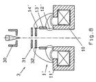
- Fig. 8 shows an application example of the shown electron beam lenses in a cathode lens 3.
- the cathode lens 3 essentially consists of a cathode 30 with "suppressor" electrode, an extraction electrode 31, an anode 32 and an electron beam lens according to one of the two in FIGS. 1a, 3 to 7 embodiments shown.
- the Electron beam lens 1 was the Electron beam lens 1 'selected according to Figure 3.
- the Electron beam lens is installed so that the secondary field 14 'forming as close as possible to the cathode 30 can be brought up and through the two pole pieces 10 ', 11' formed single-pole lens as a condenser acts.
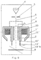
- FIG. 9 shows an application of the electron beam lens represented in an electron beam device.
- the electron beam device is made by an optical column 7 is formed, which essentially a source 4 for generating an electron beam 6, a magnetic lens 1 'and a spectrometer / detector arrangement 8 has.
- a blanking system 5 and a tiltable sample table 9 is shown.
- the electron beam lens used here corresponds to the exemplary embodiment shown in FIG. 3, in which the two first pole pieces 10 ', 11' form a single pole lens which is combined with a third pole piece 13 '.
- the electrostatic lens 2 is in turn formed by a beam tube 20 inserted into the single-pole lens as the first electrode and by the lower part of the third pole piece 13 'as the second electrode.
- the beam tube 20 and the part of the third pole piece 13 ′ serving as the second electrode can be acted upon with different potentials U L and U, respectively.
- the spectrometer / detector arrangement 8 or a detector is in the direction of the electron beam 6 arranged in front of or above the magnetic lens 1 '. It however, it would also be conceivable to place the detector within the Magnetic lens 1 'to be provided.
- the detectors can either one-sided, rotationally symmetrical or in segmented form or as a combined Backscatter / secondary electron detectors are formed his. But also an arrangement of the detector between Magnet lens and sample would be conceivable.
- the formation of the magnetic lens 1 'as a three-pole lens with the three pole pieces 10', 11 ', 13' has the further advantage that the lower end of this three-pole lens is smaller or more pointed than in conventional two-pole lenses.
- This design is particularly advantageous in the case of tiltable sample tables, since it enables a larger tilt angle ⁇ to be achieved.
- FIGS. 1a and 2a which each show the maximum tilt angle ⁇ 1 and ⁇ 2 .
- the maximum tilt angle ⁇ 1 is greater than the angle ⁇ 2 in the prior art. This property is particularly helpful when examining samples with a very short working distance, since a large tilt angle is still available.
- the additional space available can also for optional elements such as detectors, manipulators etc. can be exploited.
Landscapes
- Chemical & Material Sciences (AREA)
- Analytical Chemistry (AREA)
- Physics & Mathematics (AREA)
- Electromagnetism (AREA)
- Electron Beam Exposure (AREA)
- Electron Tubes For Measurement (AREA)
Description
Die Erfindung betrifft eine Elektronenstrahl-Linse, enthaltend eine Magnetlinse zur Beeinflussung eines Elektronenstrahls mit einem ersten und einem zweiten Polschuh, wobei sich ein Magnetfeld zwischen den beiden Polschuhen ausbildet und ferner ein dritter Polschuh vorgesehen ist. Die Erfindung bezieht sich ferner auf eine Kathodenlinse und eine Elektronenstrahlvorrichtung mit einer derartigen Elektronenstrahl-Linse.The invention relates to an electron beam lens, containing a magnetic lens to influence a Electron beam with a first and a second Pole shoe, with a magnetic field between the two Forms pole pieces and also a third pole piece is provided. The invention further relates to a cathode lens and an electron beam device with such an electron beam lens.
Bei Korpuskularstrahl-Linsen ist man bestrebt, gute optische Eigenschaften für den Primärstrahl mit guten Sammeleigenschaften für die Sekundärstrahlen zu vereinbaren. Man ist dabei von konventionellen Zweipol-Linsen, bestehend aus einem inneren und einem äußeren Polschuh, ausgegangen, wobei das linsenerzeugende Magnetfeld sich weitgehend innerhalb der körperlichen Linse befindet. Man hat in diesem Zusammenhang auch Einzelpol-Linsen eingesetzt, bei denen ein Pol hervorgezogen bzw. der magnetfelderzeugende Luftspalt am oberen oder unteren Ende der Linse angeordnet ist, so daß sich das Magnetfeld weitgehend außerhalb des Linsenkörpers ausbreitet.With corpuscular beam lenses, one strives to have good optical ones Properties for the primary beam with good To agree collection properties for the secondary rays. One is of conventional two-pole lenses, consisting of an inner and an outer pole piece, assumed that the lens-generating magnetic field largely within the physical lens located. One also has single-pole lenses in this context used where a pole was pulled out or the magnetic field generating air gap at the top or lower end of the lens is arranged so that the Magnetic field largely spreads outside the lens body.
Aus der GB-A-2 018 509 ist eine Magnetlinse zur Beeinflussung eines Elektronenstrahls bekannt, die einen oberen und einen unteren Polschuh sowie einen driffen Polschuh aufweist der zwischen den beiden anderen Polschuhen angeordnet ist und nicht in magnetischem Kontakt mit diesen steht.From GB-A-2 018 509 a magnetic lens is used Influencing an electron beam known to be an upper one and has a lower pole piece and a third pole piece which is placed between the other two pole pieces and is not in magnetic contact with them.
Aus der EP-A-0 133 016 ist eine Mehrpol-Linse bekannt, die im wesentlichen aus einer Aneinanderreihung von zwei Zweipol-Linsen der oben beschriebenen Art besteht.A multipole lens is known from EP-A-0 133 016, which essentially consists of a series of there are two bipolar lenses of the type described above.
Ausgehend von diesem Stand der Technik liegt nun der
Erfindung die Aufgabe zugrunde, die Elektronenstrahl-Linse
gemäß dem Oberbegriff des Anspruches 1 in ihren
optischen Eigenschaften für den Primärstrahl und in ihren
Sammeleigenschaften für die Sekundärstrahlen weiter
zu verbessern.Based on this state of the art
Invention based on the object, the electron beam lens
according to the preamble of
Erfindungsgemäß wird diese Aufgabe durch die kennzeichnenden
Merkmale des Anspruches 1 gelöst. Die Elektronenstrahl-Linse
zeichnet sich dadurch aus, daß der
dritte Polschuh
in das zwischen dem
ersten und zweiten Polschuh ausgebildete Magnetfeld
eintaucht und dabei einen Teil dieses Magnetfeldes auskoppelt,
wobei der
ausgekoppelte Teil des Hauptmagnetfeldes am unteren
Ende des dritten Polschuhs ein Nebenfeld ausbildet.According to the invention, this object is achieved by the characterizing
Features of
Der ausgekoppelte Teil des (Haupt-) Magnetfeldes bildet am unteren Ende des dritten Polschuhes ein zweites Linsenfeld (Nebenfeld) aus. Das Nebenfeld hat zum einen eine fokussierende Wirkung auf den Primärstrahl und aufgrund seiner Nähe zur Probe gute optische Eigenschaften und verhindert zum anderen, daß sich die Sekundärstrahlen aufweiten. Der Sekundärstrahl kann daher "gebündelt" ins Linsensystem eintreten und von einer Spektrometer/Detektor-Anordnung oder einem Detektor in oder oberhalb der Linse mit hoher Effizienz nachgewiesen werden.The decoupled part of the (main) magnetic field forms a second lens field at the lower end of the third pole piece (Secondary field). The secondary field has on the one hand a focusing effect on the primary beam and good optical properties due to its proximity to the sample and on the other hand prevents the secondary rays from moving expand. The secondary beam can therefore enter the lens system "bundled" and from one Spectrometer / detector arrangement or a detector in or above the lens with high efficiency be detected.
In einem Ausführungsbeispiel der Erfindung wird die Elektronenstrahl-Linse vorteilhaft in einer Kathoden-Linse eingesetzt. Durch das vom dritten Polschuh erzeugte Nebenfeld wird erreicht, daß sich das positiv auswirkende Magnetfeld dicht an die Kathode heranführen läßt, ohne daß hierzu eine große körperliche Linse notwendig ist. Durch geeignetes Design der dreipoligen Magnet-Linse läßt sich die Stärke des Nebenfeldes an der Kathodenspitze und die optischen Eigenschaften der als Kondensor wirkenden ersten und zweiten Polschuhe getrennt optimieren.In one embodiment of the invention, the Electron beam lens advantageous in a cathode lens used. By that generated by the third pole piece Secondary field ensures that this is positive bring the impacting magnetic field close to the cathode leaves without the need for a large physical lens is. Thanks to the suitable design of the three-pole magnetic lens can the strength of the secondary field on the Cathode tip and the optical properties of the as Condenser acting first and second pole pieces separately optimize.
In einem anderen Ausführungsbeispiel wird die Elektronenstrahl-Linse in einer Elektronenstrahl-Vorrichtung eingesetzt. Mit einem kippbaren Probenhalter können die Proben in bezug auf den Primärstrahl gekippt werden. Die spezielle Ausbildung der Elektronenstrahl-Linse ermöglicht bei kurzem Arbeitsabstand ein starkes Kippen bzw. bietet Raum für andere optionale Elemente wie Detektoren, Manipulatoren usw.In another embodiment, the electron beam lens in an electron beam device used. With a tiltable sample holder, the Samples are tilted with respect to the primary beam. The special design of the electron beam lens enables if the working distance is short, a strong tilting or offers space for other optional elements such as detectors, Manipulators etc.
Weitere Ausgestaltungen der Erfindung sind Gegenstand der Unteransprüche und werden anhand der folgenden Beschreibung einiger Ausführungsbeispiele und der Zeichnung näher erläutert.Further embodiments of the invention are the subject of the subclaims and are based on the following description some embodiments and the drawing explained in more detail.
In der Zeichnung zeigen:
- Fig.1a
- eine schematische Darstellung einer Elektronenstrahl-Linse gemäß einem ersten erfindungsgemäßen Ausführungsbeispiel;
- Fig.1b
- Darstellung der Magnetfeldverteilung der Linse gemäß Fig.1a;
- Fig.2a
- schematische Darstellung einer Elektronenstrahl-Linse gemäß dem Stand der Technik;
- Fig.2b
- Darstellung der Magnetfeldverteilung der Linse gemäß Fig.2a;
- Fig.3
- schematische Darstellung einer Elektronenstrahl-Linse gemäß einem zweiten erfindungsgemäßen Ausführungsbeispiel;
- Fig.4
- schematische Darstellung einer Elektronenstrahl-Linse gemäß einem dritten erfindungsgemäßen Ausführungsbeispiel;
- Fig.5
- schematische Darstellung einer Elektronenstrahl-Linse gemäß einem vierten erfindungsgemäßen Ausführungsbeispiel;
- Fig.6
- geschnittene Darstellung des dritten Polschuhs gemäß einem fünften Ausführungsbeispiel;
- Fig.7
- geschnittene Darstellung des dritten Polschuhs gemäß einem sechsten Ausführungsbeispiel;
- Fig.8
- schematische Darstellung einer Kathoden-Linse mit einer erfindungsgemäßen Elektronenstrahl-Linse und
- Fig.9
- schematische Darstellung einer Elektronenstrahl-Vorrichtung.
- 1a
- a schematic representation of an electron beam lens according to a first embodiment of the invention;
- 1b shows
- Representation of the magnetic field distribution of the lens according to Fig.1a;
- 2a
- schematic representation of an electron beam lens according to the prior art;
- 2b
- Representation of the magnetic field distribution of the lens according to Figure 2a;
- Figure 3
- schematic representation of an electron beam lens according to a second embodiment of the invention;
- Figure 4
- schematic representation of an electron beam lens according to a third embodiment of the invention;
- Figure 5
- schematic representation of an electron beam lens according to a fourth embodiment of the invention;
- Figure 6
- sectional view of the third pole piece according to a fifth embodiment;
- Figure 7
- sectional view of the third pole piece according to a sixth embodiment;
- Figure 8
- schematic representation of a cathode lens with an electron beam lens according to the invention and
- Figure 9
- schematic representation of an electron beam device.
Die in Fig.1a dargestellte Elektronenstrahl-Linse weist
eine Magnet-Linse 1 zur Beeinflussung eines Elektronenstrahls
mit einem ersten, inneren Polschuh 10 und einem
zweiten, äußeren Polschuh 11 auf. Der erste und zweite
Polschuh 10, 11 sind im dargestellten Ausführungsbeispiel
als Zweipol-Linse mit konisch ausgebildetem äußeren
Polschuh 11 und einer Spule 15 dargestellt, wobei
sich zwischen dem ersten und zweiten Polschuh ein magnetisches
Hauptfeld 12 ausbildet.The electron beam lens shown in Fig.1a has
a
Die Magnet-Linse 1 weist ferner einen dritten Polschuh
13 auf, der nicht in magnetischem Kontakt mit den
beiden anderen Polschuhen steht und in das zwischen dem
ersten und zweiten Polschuh 10, 11 ausgebildete Magnetfeld
eintaucht. Der dritte Polschuh 13 ist vorzugsweise
zylindrisch ausgebildet und taucht derart in das Hauptfeld
12 ein, daß ein Teil dieses Magnetfeldes ausgekoppelt
wird.The
Das am oberen Ende 13a des dritten Polschuhs 13
"aufgesaugte" Feld bildet im Bereich des unteren Endes
13b des dritten Polschuhs 13 ein magnetisches Nebenfeld
14. Ein Teil des Feldes des inneren Polschuhes 10 tritt
somit in den dritten Polschuh 13 über und stellt am
Ende 13b den Schluß zum äußeren Polschuh 11 unter Ausbildung
des Nebenfeldes her.That at the
In Fig.1b ist die Ausbreitung des Hauptfeldes 12 und
des Nebenfeldes 14 dargestellt. Durch die Einführung
des dritten Polschuhes 13 können zwei Linsenfelder in
kurzem räumlichen Abstand geschaffen werden. Die Stärke
des Nebenfeldes 14 hängt davon ab, wieweit der dritte
Polschuh 13 in das Hauptfeld eintaucht und einen entsprechenden
Anteil des Magnetfeldes auskoppelt und wie
groß der Spalt zum inneren bzw. äußeren Polschuh 10, 11
ist. Zur Einstellung der Stärke des Nebenfeldes 14 wird
der dritte Polschuh 13 zweckmäßigerweise in bezug auf
den ersten und zweiten Polschuh 10, 11 verschiebbar
bzw. verstellbar angeordnet. 1b shows the spread of the
Die Maxima der axialen Magnetfelder des Haupt- bzw. Nebenfeldes sind mit B1 bzw. B2 bezeichnet. Vorzugsweise ist der dritten Polschuh in bezug auf den ersten und zweiten Polschuh derart angeordnet, daß die Amplitude B2 des Nebenfeldes wenigstens 15 %, vorzugsweise zwischen 20 % und 60 % der Amplitude B1 des Hauptfeldes beträgt.The maxima of the axial magnetic fields of the main and secondary fields are designated B 1 and B 2 . The third pole piece is preferably arranged in relation to the first and second pole pieces such that the amplitude B 2 of the secondary field is at least 15%, preferably between 20% and 60% of the amplitude B 1 of the main field.
Zum Vergleich mit der in Fig.1a dargestellten
"magnetischen Dreipol-Linse" zeigt Fig.2a eine herkömmliche
Zweipol-Linse mit einem ersten und zweiten Pol
10, 11. Dementsprechend bildet sich auch nur ein Magnetfeld
12 aus, dessen Verteilung in Fig.2b dargestellt
ist.For comparison with that shown in Fig.1a
"Magnetic three-pole lens" shows a conventional Fig. 2a
Two-pole lens with a first and
Fig.3 zeigt ein zweites erfindungsgemäßes Ausführungsbeispiel einer Elektronenstrahl-Linse, die sich vom Ausführungsbeispiel gemäß Fig.1a lediglich dadurch unterscheidet, daß der durch einen ersten Polschuh 10' und durch einen zweiten Polschuh 11' gebildete Teil der Magnet-Linse 1' als Einzelpol-Linse ausgebildet ist. Auch hier bildet sich jedoch ein Haupt- und ein Nebenfeld 12', 14'. Der Vorteil der Verwendung einer Einzelpol-Linse in Kombination mit einem dritten Polschuh 13' besteht vor allem darin, daß mit der Einzelpol-Linse ein besonders starkes Magnetfeld erzeugt und dementsprechend auch ein starker Teil als Nebenfeld 14' weitergegeben werden kann.3 shows a second exemplary embodiment according to the invention an electron beam lens that differs from the 1a differs only in that that by a first pole piece 10 ' and formed by a second pole piece 11 ' Magnet lens 1 'is designed as a single-pole lens. Here, too, a main and a secondary field are formed 12 ', 14'. The advantage of using a single pole lens in combination with a third pole piece 13 ' is mainly that with the single pole lens generates a particularly strong magnetic field and accordingly also a strong part passed on as secondary field 14 ' can be.
Die beiden in den Fig.1a und 3 dargestellten Elektronenstrahl-Linsen
lassen sich vorteilhaft auch mit einer
elektrostatischen Linse, insbesondere einer elektrostatischen
Bremslinse kombinieren. Die elektrostatische
Linse besteht aus wenigstens einer ersten und einer
zweiten, mit unterschiedlichen Potentialen beaufschlagbaren
Elektrode. In Fig.1a ist beispielhaft eine elektrostatische
Linse 2 dargestellt, deren erste Elektrode
aus einem Strahlrohr 20 besteht, das koaxial zum
ersten Polschuh 10 im Inneren der Magnet-Linse 1 angeordnet
ist. Die zweite Elektrode wird durch den dritten
Polschuh 13 gebildet. Während das Strahlrohr 20 beispielsweise
auf hohem positiven Potential liegt, könnte
man am dritten Polschuh 13 eine geeignete, niedrigere
positive oder negative Spannung U anlegen, um die
gewünschte Bremswirkung auf den Elektronenstrahl zu
erzeugen.The two electron beam lenses shown in Figures 1a and 3
can also be advantageous with a
electrostatic lens, especially an electrostatic
Combine brake lens. The electrostatic
Lens consists of at least a first and a
second, with different potentials
Electrode. 1a is an example of an electrostatic
Shown
Für die Ausbildung der elektrostatischen Linse innerhalb
der Elektronenstrahl-Linse gibt es verschiedene
Möglichkeiten. In Fig.4 ist das Strahlrohr 20 weiter
nach unten gezogen, so daß es in den dritten Polschuh
13 eintaucht. Die elektrostatische Linse bildet sich in
diesem Fall im Bereich des eingetauchten Endes der ersten
Elektrode 20 und der angrenzenden Wandung des
dritten Polschuhs 13 aus.For the formation of the electrostatic lens inside
The electron beam lens is different
Possibilities. In Figure 4, the
Im Ausführungsbeispiel gemäß Fig.5 wird die zweite
Elektrode der elektrostatischen Linse 2 nicht durch den
dritten Polschuh 13, sondern durch eine separate, in
den Polschuh 13 eingeführte Rohrelektrode 21 gebildet.
Im Rahmen der Erfindung wäre es auch denkbar, wenn
diese Rohrelektrode 21 quer zur optischen Achse 16 ein
oder mehrmals unterbrochen ist, um dadurch die
elektrostatische Linse durch wenigstens drei Elektroden
aufzubauen.In the exemplary embodiment according to FIG. 5, the second
Electrode of the
Fig.6 zeigt eine alternative Möglichkeit zum Aufbau der elektrostatischen Linse aus mehr als zwei Elektroden. Fig. 6 shows an alternative way of building the electrostatic lens made up of more than two electrodes.
In diesem Ausführungsbeispiel bildet wiederum der
dritte Polschuh 13 einen Teil der elektrostatischen
Linse, wobei der Polschuh quer zur optischen Achse 16
in einen ersten Teil 13c und einen zweiten Teil 13d unterteilt
ist. Diese beiden Teile 13c, 13d bilden die
zweite und dritte Elektrode der elektrostatischen Linse
und können für diesen Zweck mit unterschiedlichen Potentialen
beaufschlagt werden.In this embodiment, the
Sofern man den Spalt zwischen den beiden Teilen 13c,
13d des dritten Polschuhs 13 möglichst klein wählt,
wird das "aufgesaugte" Magnetfeld ungehindert vom oberen
Ende 13a zum unteren Ende 13b geführt.Provided that the gap between the two
In Fig.7 ist ein Ausführungsbeispiel dargestellt, bei
dem die zweite Elektrode der elektrostatischen Linse
wiederum durch den dritten Polschuh gebildet wird. Dieser
dritte Polschuh ist jedoch in Richtung der optischen
Achse 16 geschlitzt ausgebildet, so daß sich im
dargestellten Ausführungsbeispiel acht Segmente 13e,
13f, 13g, 13h, 13i, 13k, 13l, 13m bilden. Diese
Segmente stellen elektrische Multipolelemente dar, die
durch geeignetes Anlegen von Spannungen als
elektrostatische Ablenker, Stigmator oder dergleichen
geschaltet und verwendet werden können. Die einzelnen
Spannungen werden dabei so gewählt, daß sich eine
mittlere Spannung ergibt, die der Spannung U der
zweiten Elektrode entspricht. Es ist aber auch ein
geringere oder größere Anzahl an Segmenten denkbar.An exemplary embodiment is shown in FIG
which is the second electrode of the electrostatic lens
is in turn formed by the third pole piece. This
third pole piece is however in the direction of the
Fig.8 zeigt ein Anwendungsbeispiel der gezeigten Elektronenstrahl-Linsen
in einer Kathoden-Linse 3. Die Kathoden-Linse
3 besteht im wesentlichen aus einer Kathode
30 mit "suppressor"-Elektrode, einer Extraktions-Elektrode
31, einer Anode 32 sowie einer Elektronenstrahl-Linse
gemäß einem der beiden in den Fig.1a, 3
bis 7 gezeigten Ausführungsbeispiele. Hier wurde die
Elektronenstrahl-Linse 1' gemäß Fig.3 ausgewählt. Die
Elektronenstrahl-Linse wird so eingebaut, daß sich das
ausbildende Nebenfeld 14' möglichst nahe an die Kathode
30 heranführen läßt und die durch die beiden Polschuhe
10', 11' gebildete Einzelpol-Linse als Kondensor
wirkt.Fig. 8 shows an application example of the shown electron beam lenses
in a
Durch geeignetes Design der drei Polschuhe 10', 11', 13' lassen sich die Magnetfeldstärke des Nebenfeldes 14' an der Kathode und die optischen Eigenschaften des Hauptfeldes 12' getrennt voneinander optimieren.Due to the suitable design of the three pole shoes 10 ', 11', 13 'can be the magnetic field strength of the secondary field 14 'on the cathode and the optical properties of the Optimize main field 12 'separately.
In Fig.9 ist schließlich eine Anwendung der Elektronenstrahl-Linse
in einer Elektronenstrahl-Vorrichtung dargestellt.
Die Elektronenstrahl-Vorrichtung wird durch
eine optische Säule 7 gebildet, die im wesentlichen
eine Quelle 4 zur Erzeugung eines Elektronenstrahls 6,
eine Magnet-Linse 1' sowie eine Spektrometer/Detektor-Anordnung
8 aufweist. Neben einer Vielzahl von magnetischen
und/oder elektrischen Linsen und Blenden zur Beeinflussung
des Elektronenstrahls ist im Ausführungsbeispiel
gemäß Fig.9 ferner noch ein Austastsystem 5
und ein kippbarer Probentisch 9 dargestellt.Finally, FIG. 9 shows an application of the electron beam lens
represented in an electron beam device.
The electron beam device is made by
an
Die hier verwendete Elektronenstrahl-Linse entspricht
wiederum dem in Fig.3 dargestellten Ausführungsbeispiel,
bei dem die beiden ersten Polschuhe 10', 11'
eine Einzelpol-Linse bilden, die mit einem dritten Polschuh
13' kombiniert wird. Die elektrostatische Linse 2
wird wiederum durch ein in die Einzelpol-Linse eingeführtes
Strahlrohr 20 als erste Elektrode und durch den
unteren Teil des dritten Polschuhs 13' als zweite Elektrode
gebildet. Das Strahlrohr 20 und der als zweite
Elektrode dienende Teil des dritten Polschuhs 13' können
mit unterschiedlichen Potentialen UL bzw. U beaufschlagt
werden.The electron beam lens used here in turn corresponds to the exemplary embodiment shown in FIG. 3, in which the two first pole pieces 10 ', 11' form a single pole lens which is combined with a third pole piece 13 '. The
Die dargestellte Spektrometer/Detektor-Anordnung 8 bzw.
ein Detektor ist in Richtung des Elektronenstrahls 6
vor bzw. oberhalb der Magnetlinse 1' angeordnet. Es
wäre jedoch auch denkbar, den Detektor innerhalb der
Magnetlinse 1' vorzusehen. Die Detektoren können
wahlweise einseitig, rotationssymmetrisch oder in
segmentierter Form oder aber auch als kombinierte
Rückstreu-/Sekundär-Elektronen-Detektoren ausgebildet
sein. Aber auch eine Anordnung des Detektors zwischen
Magnet-Linse und Probe wäre denkbar.The spectrometer /
Das sich zwischen der auf dem Probentisch 9 angeordneten
Probe und dem unteren Ende 13'b des dritten Polschuhs
13' ausbildende Nebenfeld hat zum einen eine fokussierende
Wirkung auf den primären Elektronenstrahl
und zum andern aufgrund seiner Nähe zur Probe gute optische
Eigenschaften. Dieses Nebenfeld bewirkt zudem,
daß sich die ausgelösten Sekundär-Elektronen nicht aufweiten,
sondern vielmehr gebündelt in die Elektronenstrahl-Linse
eintreten und von der Spektrometer/Detektor-Anordnung
8 mit hoher Effizienz nachgewiesen
werden können.That between the arranged on the sample table 9
Probe and the lower end 13'b of the third pole piece
13 'training secondary field on the one hand has a focusing
Effect on the primary electron beam
and secondly, due to its proximity to the sample, good optical
Characteristics. This secondary field also causes
that the released secondary electrons do not expand,
but rather bundled into the electron beam lens
enter and from the spectrometer /
Es ist durchaus denkbar, am dritten Polschuh 13' eine positive Absaugspannung anzulegen, wobei jedoch auch eine zusätzliche Elektrode verwendet werden kann. Vorteilhaft sind jedoch positive Absaugfelder mit Spannungen unterhalb von 100 V, da so die elektrische Aufladung von isolierenden Proben minimiert wird. Aber auch höhere elektrische Felder und damit eine kombiniert elektrisch/magnetische Linse sind denkbar und gegebenenfalls erstrebenswert.It is quite conceivable to have one on the third pole shoe 13 ' to apply positive suction voltage, but also an additional electrode can be used. Advantageous are positive suction fields with tensions below 100 V because of the electrical charge of isolating samples is minimized. But also higher electric fields and thus one combined electrical / magnetic lens are conceivable and possibly desirable.
Die Ausbildung der Magnetlinse 1' als Dreipol-Linse mit den drei Polschuhen 10', 11', 13' hat weiterhin den Vorteil, daß das untere Ende dieser Dreipol-Linse kleiner bzw. spitzer als bei herkömmlichen Zweipol-Linsen ausgebildet ist. Diese Ausbildung ist insbesondere bei kippbaren Probentischen von besonderem Vorteil, da hierdurch ein größerer Kippwinkel α erzielt werden kann. In diesem Zusammenhang sei nochmals auf die beiden Fig.1a und 2a verwiesen, die jeweils den maximalen Kippwinkel α1 bzw. α2 zeigen. Bei der erfindungsgemäßen Elektronenstrahl-Linse ist der maximale Kippwinkel α1 größer als der Winkel α2 beim Stand der Technik. Diese Eigenschaft ist insbesondere bei der Untersuchung von Proben mit sehr kurzem Arbeitsabstand hilfreich, da auch dann noch ein großer Kippwinkel zur Verfügung steht.The formation of the magnetic lens 1 'as a three-pole lens with the three pole pieces 10', 11 ', 13' has the further advantage that the lower end of this three-pole lens is smaller or more pointed than in conventional two-pole lenses. This design is particularly advantageous in the case of tiltable sample tables, since it enables a larger tilt angle α to be achieved. In this context, reference is again made to the two FIGS. 1a and 2a, which each show the maximum tilt angle α 1 and α 2 . In the electron beam lens according to the invention, the maximum tilt angle α 1 is greater than the angle α 2 in the prior art. This property is particularly helpful when examining samples with a very short working distance, since a large tilt angle is still available.
Sofern der Probentisch nicht kippbar ausgeführt ist, kann der zusätzlich zur Verfügung stehende Raum auch für optionale Elemente wie Detektoren, Manipulatoren usw. ausgenutzt werden.If the sample table is not tiltable, the additional space available can also for optional elements such as detectors, manipulators etc. can be exploited.
Claims (16)
- Electron beam lens which contains a magnetic lens (1; 1') for influencing an electron beam (6) and which has a first and a second pole piece (10, 11; 10', 11'), a primary magnetic field (12) being produced between the two pole pieces and a third pole piece (13; 13') additionally being provided which is not in magnetic contact with the other two pole pieces,
characterised in that the third pole piece is introduced into the primary magnetic field (12) which is produced between the first and second pole piece and decouples a portion of this magnetic field, the decoupled portion of the primary magnetic field producing a secondary field at the lower end of the third pole piece. - Electron beam lens according to claim 1, characterised in that the third pole piece (13; 13') is constructed in a cylindrical manner.
- Electron beam lens according to claim 1, characterised in that the third pole piece (13; 13') is arranged so as to be adjustable relative to the first and second pole piece (10, 11, 10', 11').
- Electron beam lens according to claim 1, characterised in that the first pole piece (10) and second pole piece (11) are constructed as a two-pole lens.
- Electron beam lens according to claim 4, characterised in that the two-pole lens is constructed in a conical manner.
- Electron beam lens according to claim 1, characterised in that the first pole piece (10') and second pole piece (11') are constructed as a single-pole lens.
- Electron beam lens according to claim 1, characterised in that an electrostatic lens (2) is provided within the magnetic lens (1; 1').
- Electron beam lens according to claim 7, characterised in that the electrostatic lens (2) is constructed as a retarding lens.
- Electron beam lens according to claim 7, characterised in that the electrostatic lens (2) has at least a first and a second electrode which can be subjected to different potentials.
- Electron beam lens according to claim 7, characterised in that the electrostatic lens (2) has at least two electrodes, one electrode being formed by the third pole piece (13; 13').
- Electron beam lens according to claim 10, characterised in that the third pole piece is divided into segments which can be subjected to different potentials.
- Electron beam lens according to claim 7, characterised in that the electrostatic lens (2) has at least two electrodes, one electrode being introduced as a beam tube (20) through a portion of the magnetic lens (1; 1'), which portion is formed by the first and second pole piece (10, 11; 10', 11').
- Cathode lens (3) havinga cathode (30),an extraction electrode (31),an anode (32)and an electron beam lens according to any one of claims 1 to 11.
- Electron beam device havinga source (4) for producing an electron beam (6),an electron beam lens for focusing the electron beam on a sample according to any one of claims 1 to 11.
- Electron beam device according to claim 14, characterised in that a tiltable sample table (9) is provided.
- Electron beam device according to claim 14, characterised in that a spectrometer/detector arrangement is provided in order to detect secondary particles which are released from the sample.
Priority Applications (4)
| Application Number | Priority Date | Filing Date | Title |
|---|---|---|---|
| DE59712097T DE59712097D1 (en) | 1997-09-29 | 1997-09-29 | Electron lens |
| EP97116909A EP0910108B1 (en) | 1997-09-29 | 1997-09-29 | Electron beam lens |
| US09/113,048 US6107633A (en) | 1997-09-29 | 1998-07-09 | Electron beam lens |
| JP10233055A JPH11120950A (en) | 1997-09-29 | 1998-08-19 | Electron beam lens device |
Applications Claiming Priority (1)
| Application Number | Priority Date | Filing Date | Title |
|---|---|---|---|
| EP97116909A EP0910108B1 (en) | 1997-09-29 | 1997-09-29 | Electron beam lens |
Publications (2)
| Publication Number | Publication Date |
|---|---|
| EP0910108A1 EP0910108A1 (en) | 1999-04-21 |
| EP0910108B1 true EP0910108B1 (en) | 2004-11-24 |
Family
ID=8227414
Family Applications (1)
| Application Number | Title | Priority Date | Filing Date |
|---|---|---|---|
| EP97116909A Expired - Lifetime EP0910108B1 (en) | 1997-09-29 | 1997-09-29 | Electron beam lens |
Country Status (4)
| Country | Link |
|---|---|
| US (1) | US6107633A (en) |
| EP (1) | EP0910108B1 (en) |
| JP (1) | JPH11120950A (en) |
| DE (1) | DE59712097D1 (en) |
Families Citing this family (12)
| Publication number | Priority date | Publication date | Assignee | Title |
|---|---|---|---|---|
| US6787772B2 (en) * | 2000-01-25 | 2004-09-07 | Hitachi, Ltd. | Scanning electron microscope |
| WO2001096843A1 (en) * | 2000-06-15 | 2001-12-20 | Kla-Tencor, Inc. | Apparatus and method for applying feedback control to a magnetic lens |
| WO2001097245A2 (en) * | 2000-06-15 | 2001-12-20 | Kla-Tencor, Inc. | Sectored magnetic lens and method of use |
| JP2002134051A (en) * | 2000-10-20 | 2002-05-10 | Seiko Instruments Inc | Electromagnetic field superimposed lens and electron beam device using the same |
| DE10233002B4 (en) * | 2002-07-19 | 2006-05-04 | Leo Elektronenmikroskopie Gmbh | Objective lens for an electron microscopy system and electron microscopy system |
| DE10317894B9 (en) | 2003-04-17 | 2007-03-22 | Leo Elektronenmikroskopie Gmbh | Charged particle focusing system, electron microscopy system and electron microscopy method |
| JP4588602B2 (en) * | 2005-09-30 | 2010-12-01 | 株式会社トプコン | Manufacturing method of electrostatic deflector |
| EP2211368B1 (en) | 2005-11-28 | 2012-06-27 | Carl Zeiss SMT GmbH | Particle-optical component |
| DE102007010873B4 (en) | 2007-03-06 | 2009-07-30 | Carl Zeiss Nts Gmbh | objective lens |
| US8294095B2 (en) * | 2010-12-14 | 2012-10-23 | Hermes Microvision, Inc. | Apparatus of plural charged particle beams with multi-axis magnetic lens |
| WO2015166849A1 (en) | 2014-04-28 | 2015-11-05 | 株式会社日立ハイテクノロジーズ | Electron beam device |
| WO2019100600A1 (en) * | 2017-11-21 | 2019-05-31 | Focus-Ebeam Technology (Beijing) Co., Ltd. | Low voltage scanning electron microscope and method for specimen observation |
Family Cites Families (9)
| Publication number | Priority date | Publication date | Assignee | Title |
|---|---|---|---|---|
| JPS5842935B2 (en) * | 1978-04-07 | 1983-09-22 | 日本電子株式会社 | Objective lenses for scanning electron microscopes, etc. |
| JPS57118357A (en) * | 1981-01-14 | 1982-07-23 | Jeol Ltd | Objective lens for scan type electron microscope |
| US4544847A (en) * | 1983-07-28 | 1985-10-01 | Varian Associates, Inc. | Multi-gap magnetic imaging lens for charged particle beams |
| FR2644930B1 (en) * | 1989-03-21 | 1996-04-26 | Cameca | VARIABLE FOCAL COMPOSITE ELECTROMAGNETIC LENS |
| US5644132A (en) * | 1994-06-20 | 1997-07-01 | Opan Technologies Ltd. | System for high resolution imaging and measurement of topographic and material features on a specimen |
| TW306009B (en) * | 1995-09-05 | 1997-05-21 | Matsushita Electron Co Ltd | |
| US5780859A (en) * | 1996-02-16 | 1998-07-14 | Act Advanced Circuit Testing Gesellschaft | Electrostatic-magnetic lens arrangement |
| DE69602936T2 (en) * | 1996-07-25 | 1999-11-04 | Act Advanced Circuit Testing | Detector objective lens |
| JPH10255705A (en) * | 1997-03-13 | 1998-09-25 | Nikon Corp | Double symmetric magnetic lenses and two step magnetic lens system |
-
1997
- 1997-09-29 EP EP97116909A patent/EP0910108B1/en not_active Expired - Lifetime
- 1997-09-29 DE DE59712097T patent/DE59712097D1/en not_active Expired - Fee Related
-
1998
- 1998-07-09 US US09/113,048 patent/US6107633A/en not_active Expired - Fee Related
- 1998-08-19 JP JP10233055A patent/JPH11120950A/en active Pending
Also Published As
| Publication number | Publication date |
|---|---|
| EP0910108A1 (en) | 1999-04-21 |
| JPH11120950A (en) | 1999-04-30 |
| US6107633A (en) | 2000-08-22 |
| DE59712097D1 (en) | 2004-12-30 |
Similar Documents
| Publication | Publication Date | Title |
|---|---|---|
| EP0218920B1 (en) | Omega-type electron energy filter | |
| EP0333018B1 (en) | Objective lens for focusing charged particles | |
| EP0242602B1 (en) | Electrostatic and magnetic lens for corpuscular beam apparatus | |
| DE2850411C2 (en) | Electron gun in a cathode ray tube | |
| EP0617451B1 (en) | Imaging electron energy filter | |
| DE19732093B4 (en) | Charged particle beam | |
| EP0461442B1 (en) | Particle beam apparatus | |
| EP1277221B1 (en) | Electron/ion gun for electron or ion beams with high monochromasy or high current density | |
| DE3913965A1 (en) | DIRECTLY IMAGING SECOND EDITION MASS SPECTROMETER WITH RUNTIME MASS SPECTROMETRIC MODE | |
| EP0910108B1 (en) | Electron beam lens | |
| DE69920182T2 (en) | CORPUSCULAR-STRAHLOPTISCHES DEVICE WITH AUGER ELECTRON DETECTION | |
| DE2255302C3 (en) | Equipment for secondary ion mass spectroscopy | |
| DE10235456B4 (en) | electron microscopy system | |
| EP0911860B1 (en) | Particle beam apparatus with energy filter | |
| DE69633338T2 (en) | Electrostatic device for acting on a corpuscular beam | |
| EP0910109B1 (en) | Objective lens | |
| DE69817618T2 (en) | VIENNA FILTER | |
| DE4037029C2 (en) | Electron gun for a color cathode ray tube | |
| DE2608958A1 (en) | DEVICE FOR GENERATING RAYS FROM CHARGED PARTICLES | |
| DE102010001349B9 (en) | Device for focusing and for storing ions | |
| DE69633505T2 (en) | deflection | |
| DE2004256A1 (en) | Method and device for surface analysis using an electron beam | |
| DE2659385C3 (en) | Ion microprobe analyzer | |
| DE102004037781A1 (en) | electron beam device | |
| EP1454334A2 (en) | Lens array with a laterally movable optical axis for corpuscular rays |
Legal Events
| Date | Code | Title | Description |
|---|---|---|---|
| PUAI | Public reference made under article 153(3) epc to a published international application that has entered the european phase |
Free format text: ORIGINAL CODE: 0009012 |
|
| 17P | Request for examination filed |
Effective date: 19980515 |
|
| AK | Designated contracting states |
Kind code of ref document: A1 Designated state(s): DE FR GB NL |
|
| AKX | Designation fees paid |
Free format text: DE FR GB NL |
|
| 17Q | First examination report despatched |
Effective date: 20000222 |
|
| GRAP | Despatch of communication of intention to grant a patent |
Free format text: ORIGINAL CODE: EPIDOSNIGR1 |
|
| GRAS | Grant fee paid |
Free format text: ORIGINAL CODE: EPIDOSNIGR3 |
|
| GRAA | (expected) grant |
Free format text: ORIGINAL CODE: 0009210 |
|
| AK | Designated contracting states |
Kind code of ref document: B1 Designated state(s): DE FR GB NL |
|
| REG | Reference to a national code |
Ref country code: GB Ref legal event code: FG4D Free format text: NOT ENGLISH |
|
| REF | Corresponds to: |
Ref document number: 59712097 Country of ref document: DE Date of ref document: 20041230 Kind code of ref document: P |
|
| GBT | Gb: translation of ep patent filed (gb section 77(6)(a)/1977) |
Effective date: 20050113 |
|
| ET | Fr: translation filed | ||
| PLBE | No opposition filed within time limit |
Free format text: ORIGINAL CODE: 0009261 |
|
| STAA | Information on the status of an ep patent application or granted ep patent |
Free format text: STATUS: NO OPPOSITION FILED WITHIN TIME LIMIT |
|
| 26N | No opposition filed |
Effective date: 20050825 |
|
| PGFP | Annual fee paid to national office [announced via postgrant information from national office to epo] |
Ref country code: NL Payment date: 20080821 Year of fee payment: 12 Ref country code: FR Payment date: 20080811 Year of fee payment: 12 |
|
| PGFP | Annual fee paid to national office [announced via postgrant information from national office to epo] |
Ref country code: GB Payment date: 20080822 Year of fee payment: 12 |
|
| PGFP | Annual fee paid to national office [announced via postgrant information from national office to epo] |
Ref country code: DE Payment date: 20081120 Year of fee payment: 12 |
|
| REG | Reference to a national code |
Ref country code: NL Ref legal event code: V1 Effective date: 20100401 |
|
| GBPC | Gb: european patent ceased through non-payment of renewal fee |
Effective date: 20090929 |
|
| REG | Reference to a national code |
Ref country code: FR Ref legal event code: ST Effective date: 20100531 |
|
| PG25 | Lapsed in a contracting state [announced via postgrant information from national office to epo] |
Ref country code: NL Free format text: LAPSE BECAUSE OF NON-PAYMENT OF DUE FEES Effective date: 20100401 Ref country code: FR Free format text: LAPSE BECAUSE OF NON-PAYMENT OF DUE FEES Effective date: 20090930 Ref country code: DE Free format text: LAPSE BECAUSE OF NON-PAYMENT OF DUE FEES Effective date: 20100401 |
|
| PG25 | Lapsed in a contracting state [announced via postgrant information from national office to epo] |
Ref country code: GB Free format text: LAPSE BECAUSE OF NON-PAYMENT OF DUE FEES Effective date: 20090929 |