EP0205107A2 - Zentrifuge - Google Patents
Zentrifuge Download PDFInfo
- Publication number
- EP0205107A2 EP0205107A2 EP86107648A EP86107648A EP0205107A2 EP 0205107 A2 EP0205107 A2 EP 0205107A2 EP 86107648 A EP86107648 A EP 86107648A EP 86107648 A EP86107648 A EP 86107648A EP 0205107 A2 EP0205107 A2 EP 0205107A2
- Authority
- EP
- European Patent Office
- Prior art keywords
- card
- aperture
- filter card
- slide
- deposit
- Prior art date
- Legal status (The legal status is an assumption and is not a legal conclusion. Google has not performed a legal analysis and makes no representation as to the accuracy of the status listed.)
- Granted
Links
Images
Classifications
-
- G—PHYSICS
- G01—MEASURING; TESTING
- G01N—INVESTIGATING OR ANALYSING MATERIALS BY DETERMINING THEIR CHEMICAL OR PHYSICAL PROPERTIES
- G01N1/00—Sampling; Preparing specimens for investigation
- G01N1/28—Preparing specimens for investigation including physical details of (bio-)chemical methods covered elsewhere, e.g. G01N33/50, C12Q
- G01N1/2813—Producing thin layers of samples on a substrate, e.g. smearing, spinning-on
- G01N2001/2846—Cytocentrifuge method
Definitions
- This invention concerns the centrifugation of suspensions to effect separation of solids therefrom for, e.g., microscopic examination.
- the invention is especially concerned with the centrifugation of body fluid and like samples comprising cell suspensions to accomplish deposition of a cell layer on a slide or other receiving surface for cytological examination, a general objective of the invention being to facilitate and improve the preparation of such cell layers in routine cytological screening procedures, e.g., in the screening of cervical cell samples for carcinoma.
- the sample chamber is sized to deposit cells on a rather small, generally circular, area of the slide and handles correspondingly small samples of cell suspension.
- the rather small areas of cell deposit thereby produced are adequate for microscopic examination by a suitably trained operative making a visual examination but it is recognised that examination of the deposit would be facilitated if the deposit were spread over a larger area of the slide and, ideally, as a monolayer of cells.
- the uniform deposition of cells in a monolayer over a substantial area would, for instance, greatly facilitate counting of cells per unit area as well as the recognition of particular cell types of interest.
- recent proposals for the automated examination of cell deposits by optical scanning devices require, for reproducibility of results, cells to be deposited in a monolayer over a, preferably rectangular, relatively large area of a suitable receiving surface such as a glass slide.
- the arrangement should be such that, under the artificial gravitational field created by centrifugation, solids (e.g. cells) suspended in the sample are caused to deposit on the receiving surface before there is any significant flow of the suspending liquid transversely of that surface and into the surrounding filter card, to cause lateral displacement of suspended solids before these are deposited.
- solids e.g. cells
- the flow of suspending liquid into the surrounding filter card, when it occurs, should be slow to minimise the risk of currents over the deposited solids disturbing these and altering their disposition on the surface.
- any flow-induced migration of suspended solids towards the periphery of the deposit area will be essentially uniform so that unacceptable thickening of the deposited layer will be confined to a substantially uniform width marginal band that can be ignored without difficulty in subsequent visual inspection and that can also be readily ignored by an automated optical scanning of the deposit area.
- the volumetric flow rate of a liquid by capillary action in the card material it is directly proportional to the cross-sectional area of the material in the flow path of the liquid. Accordingly the flow of liquid in a filter card from a particular region of the perimeter of an aperture therein can be restrained by restricting the flow cross-sectional area available in the card material for liquid flowing from that region of the aperture perimeter.
- This cross-sectional area restriction may be accomplished by physical removal of material, to form openings constituting liquid flow barriers therein as by cutting slots transverse to a liquid flow path to be restricted, by localised impregnation of the card with an occlusive, e.g. a hydrophobic, agent so as to inhibit liquid flow in the filter card region so impregnated, or by localised compression, as by clamping, of the card.
- the present invention provides a centrifugation apparatus including a sample chamber, a deposit-receiving surface and a filter card apertured to define on that surface a deposition area communicating with said sample chamber, characterised by said filter card having liquid flow paths from the perimeter of said aperture of selectively restricted cross-sectional area to engender constant velocity flow of liquid from the sample chamber substantially normal to all points on the periphery of said aperture.
- the filter card aperture is rectangular and liquid flow paths in the filter card from the periphery of said aperture are selectively restricted in strip-like areas near and parallel with at least the intermediate regions of edges of the aperture.
- the deposit-receiving surface is conveniently constituted by the surface of a slide, for instance a standard glass microscope slide (75mm x 25mm) and the filter card is rectangular, having one dimension about 60mm (i.e. corresponding to about 80% of the length of the slide) and its other dimension about 50mm (i.e. approximating to twice the width of the slide) so that by folding the card may be wrapped around and overlie both faces of approximately 80% of the length of the slide.
- Such a card may be formed with a rectangular aperture the length of which is about 25mm and the width of which is about 20mm so as to be slightly less than the width (25mm) of the slide and in a position to define a deposit-receiving area of corresponding shape nearer to one end of one face of the slide when the card is superimposed on the slide and folded and wrapped thereabout.
- the aperture in the card may be arranged symmetrically of the total area of the latter to simplify control of liquid flow in the card from the perimeter of the aperture therein.
- an asymmetrical arrangement is preferred with the aperture located near to (e.g., about 2 - 3mm from) one edge of the card so that by single folding of the card about its longer axis, it may be wrapped over one long edge of the slide with the card aperture appropriately positioned over one face of the slide.
- the tendency to asymmetric liquid flow in the card resulting from the asymmetrical location of the aperture therein may be compensated, in accordance with the invention, by suitably controlling the available liquid flow cross-sectional areas in the card adjacent to those edges of the aperture more remote from edges of the card.
- Centrifugation apparatus in accordance with the invention is especially advantageous for use in conjunction with a sample chamber of the construction disclosed in our co-pending Application No. (Agents' Ref. FB 1222) and/or for use in a cytocentrifuge of the construction disclosed in our co-pending Application No. , (Agents' Ref. FB 1223) both filed concurrently herewith.
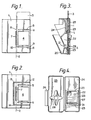
- the filter card I is rectangular in shape, having a longer dimension about 60 mm and a shorter dimension about 50 mm.
- the longer axis of the card I is indicated at 2 while the outline of a standard glass microscope slide, 75 mm by 25 mm, is shown at 3 superimposed over one half of the card I.
- the card I is formed with a rectangular aperture 4 having a length of about 25 mm and a width of about 20 mm and symmetrically disposed within one half of the total width of the card I so as, as shown, to define on the slide 3 a correspondingly shaped deposit-receiving area, the longer edges of which are parallel to and equidistant from the long edges of the slide.
- the card I is also formed with liquid flow barriers, in this case in the form of three slots 5, 6, 7 parallel, respectively, with the upper and lower short edges of the aperture 4, and with the long edge of the aperture 4 adjacent to the long axis 2 of the card.
- the purpose of these slots is to restrict the cross-section available, in the card material, for flow of liquid from the perimeter of the aperture 4 into the main body of the card beyond the slots 5, 6 and 7: in this embodiment these slots form the only such flow path restrictions and effectively confine any flow of liquid from the perimeter of the aperture 4, to the card regions indicated at 8, 9, 10 and I respectively adjacent to the four corners of the aperture 4.
- the unapertured half of the card I to the left of its axis 2 as seen in Figure I, constitutes a sump for liquid that in use enters the card at the perimeter of the aperture 4.
- the band 12 is shown as consisting of three linear legs respectively extending parallel with the slots 5, 6 and 7 and joined to one another to form a continuous band surrounding the aperture 4 and the slots 5, 6 and 7 and terminating at the right hand edge of the card I as seen in the drawing.
- the band 12 may have other shapes and may be interrupted to provide for precise control of liquid flow from particular regions of the perimeter of the aperture 4 into the main body of the filter card I external of the band.
- a suitably shaped band 12 continuous as shown or interrupted, for instance at the corner regions 13 and 14, may be used to control liquid flow in a filter card from which one or more of the slots 5, 6 and 7 has been omitted.
- the bond 12 may conveniently be formed by a printing-like operation, the chosen occlusive or hydrophobic material (e.g. a solution of a rubber in a suitable solvent) being imprinted on or applied to the card using, for instance, a stencil.
- the chosen occlusive or hydrophobic material e.g. a solution of a rubber in a suitable solvent
- the liquid flow barrier constituted as above described by a slot such as one of the slots 5, 6, 7, or by impregnation with an occlusive material in a band or region such as the band 12, may alternatively be provided by local compression of the card material to reduce the available cross section for liquid flow in the card material.
- localised compression could be achieved by clamping the card against the slide 3 or other deposit-receiving member with the use of pressure members, such as ribs on a holder for the card and slide assembly, disposed engage the card and indent it in the regions requiring localised compression.
- a filter card such as has been described with reference to Figures ! and 2 is intended to be used in conjunction with a suitable sample chamber that is assembled with the card and a suitable deposit-receiving surface such as that of a microscope slide 3, and so fitted to a centrifuge head that the artificial gravitational field produced by operation of the centrifuge acts normal to the deposit-receiving surface to accomplish controlled deposition of solids from a suspension contained in the sample chamber.
- the apertured filter card with its restricted liquid flow paths from the aperture therein may be used with any design of sample chamber capable of making up the required assembly with the card and deposit-receiving surface or slide and, for example, a sample chamber having a configuration generally similar to that disclosed in EP-A-0 047 840 might be employed.
- Figure 3 is a longitudinal section of the sample chamber, and also shows a filter card I and slide 3 installed therein.
- the sample chamber is a moulding in a suitable plastics material and includes a sample reservoir 20 communicating via a slot 21 with o deposition chamber 22 that is rectangular in cross-section with a longer dimension - vertically as seen in Figure 3 - of about 25 mm and o shorter dimension of about 20 mm, the deposition chamber 22 terminating in a narrow rectangular aperture- defining wall 23 that projects as a rib on the rear surface of the main body part 24 of the sample chamber.
- the sample chamber is formed with an integrally hinged rear door 25, shown in its open condition in Figure 4, with a latch 26 that in the closed condition of the door engages over a series of dog teeth 27 on the body 24.
- the internal face of the door 25 is formed with a cruciform pressure pad 28.
- a filter card of the configuration and dimensions illustrated in Figure or Figure 2 is fitted to the sample chamber so that its aperture 4 registers with the deposit chamber 22, the card at the margin of the aperture 4 therein engaging the end surface of the wall 23.
- the card is conveniently secured in place in the sample chamber as by ultrasonic welding to the pressure pad 28, to form a one-use, disposable, unit, perhaps supplied in a sterile pock.
- the sample chamber of Figures 3 and 4 is intended to be used with standard microscope slides such as the slide 3 depicted in Figure I and in use such a slide is placed over the apertured half of the card I - as in Figure I - that in turn has been placed or fixed in position relatively to the deposition chamber of the sample chamber.
- the card is folded about its axis 2 so as to become wrapped about the slide with the unapertured area of the card lying against the face of the slide remote from the deposit chamber 22.
- this folding of the card is accomplished simply by closing the rear door 25 of the sample chamber, whereby the pressure pad 28 holds the slide firmly against the wall 23 without, however, placing more than a small proportion of the total area of the filter card (the region trapped between the slide and the wall 23 on the front of the slide, and the region trapped between the slide and the pressure pad 28 at the rear of the slide) under such pressure as would diminish the capability of the card to absorb liquid, or interfere with flow of liquid in sump-constituting areas of the card.
- the slots 5 and 6 in the card lie just outboard of the wall 23.
- sample chamber with filter card and slide is intended to be fitted to a complementary bucket on the head of a centrifuge, to enable centrifugation of a suspension sample placed in the sample reservoir 20, the sample being transferred from this reservoir through the slot 21 to the deposition chamber 22 by the artificial gravitational field produced when the centrifuge is run up.
Landscapes
- General Health & Medical Sciences (AREA)
- Health & Medical Sciences (AREA)
- Life Sciences & Earth Sciences (AREA)
- Chemical & Material Sciences (AREA)
- Analytical Chemistry (AREA)
- Biochemistry (AREA)
- Physics & Mathematics (AREA)
- General Physics & Mathematics (AREA)
- Immunology (AREA)
- Pathology (AREA)
- Sampling And Sample Adjustment (AREA)
- Centrifugal Separators (AREA)
- Investigating Or Analysing Biological Materials (AREA)
Priority Applications (1)
| Application Number | Priority Date | Filing Date | Title |
|---|---|---|---|
| AT86107648T ATE41706T1 (de) | 1985-06-10 | 1986-06-05 | Zentrifuge. |
Applications Claiming Priority (2)
| Application Number | Priority Date | Filing Date | Title |
|---|---|---|---|
| GB858514589A GB8514589D0 (en) | 1985-06-10 | 1985-06-10 | Centrifugation |
| GB8514589 | 1985-06-10 |
Publications (3)
| Publication Number | Publication Date |
|---|---|
| EP0205107A2 true EP0205107A2 (de) | 1986-12-17 |
| EP0205107A3 EP0205107A3 (en) | 1988-05-04 |
| EP0205107B1 EP0205107B1 (de) | 1989-03-22 |
Family
ID=10580451
Family Applications (1)
| Application Number | Title | Priority Date | Filing Date |
|---|---|---|---|
| EP86107648A Expired EP0205107B1 (de) | 1985-06-10 | 1986-06-05 | Zentrifuge |
Country Status (6)
| Country | Link |
|---|---|
| US (1) | US4696743A (de) |
| EP (1) | EP0205107B1 (de) |
| JP (1) | JPH0718782B2 (de) |
| AT (1) | ATE41706T1 (de) |
| DE (1) | DE3662562D1 (de) |
| GB (1) | GB8514589D0 (de) |
Cited By (1)
| Publication number | Priority date | Publication date | Assignee | Title |
|---|---|---|---|---|
| EP0880021A1 (de) * | 1997-05-23 | 1998-11-25 | Shandon Scientific Limited | Anordnung zur Zentrifugen-Aufbereitung von zytologischen Proben |
Families Citing this family (10)
| Publication number | Priority date | Publication date | Assignee | Title |
|---|---|---|---|---|
| USD306480S (en) | 1986-07-16 | 1990-03-06 | Shandon Scientific Limited | Deposition chamber for use in the centrifugation of suspensions to effect separation of solids |
| US5252228A (en) * | 1991-11-05 | 1993-10-12 | Wescor, Inc. | Cytocentrifugation device, apparatus, and method |
| US5470758A (en) * | 1994-12-14 | 1995-11-28 | Shandon, Inc. | Large cytology sample chamber for distributing material onto a microscope slide |
| US7754155B2 (en) * | 2002-03-15 | 2010-07-13 | Ross Amelia A | Devices and methods for isolating target cells |
| GB0301047D0 (en) | 2003-01-16 | 2003-02-19 | Thermo Shandon Ltd | A centrifugation device |
| GB0319709D0 (en) * | 2003-08-21 | 2003-09-24 | Thermo Shandon Ltd | A centrifugation device |
| NZ540060A (de) * | 2005-05-16 | 2008-01-31 | Lab Tek Internat Ltd | |
| US7758816B2 (en) * | 2007-03-01 | 2010-07-20 | Wescor Inc. | Large area cytocentrifuge sample chamber |
| US11435267B1 (en) | 2022-06-14 | 2022-09-06 | Angle Europe Limited | Cell recovery method and device |
| JP2025520492A (ja) | 2022-06-15 | 2025-07-03 | アングル・ユーロプ・リミテッド | 細胞回収方法および装置 |
Family Cites Families (1)
| Publication number | Priority date | Publication date | Assignee | Title |
|---|---|---|---|---|
| ATE12024T1 (de) * | 1980-09-15 | 1985-03-15 | Shandon Southern Prod | Zyto-zentrifuge. |
-
1985
- 1985-06-10 GB GB858514589A patent/GB8514589D0/en active Pending
-
1986
- 1986-06-05 US US06/871,061 patent/US4696743A/en not_active Expired - Lifetime
- 1986-06-05 EP EP86107648A patent/EP0205107B1/de not_active Expired
- 1986-06-05 AT AT86107648T patent/ATE41706T1/de not_active IP Right Cessation
- 1986-06-05 DE DE8686107648T patent/DE3662562D1/de not_active Expired
- 1986-06-10 JP JP61134727A patent/JPH0718782B2/ja not_active Expired - Fee Related
Cited By (1)
| Publication number | Priority date | Publication date | Assignee | Title |
|---|---|---|---|---|
| EP0880021A1 (de) * | 1997-05-23 | 1998-11-25 | Shandon Scientific Limited | Anordnung zur Zentrifugen-Aufbereitung von zytologischen Proben |
Also Published As
| Publication number | Publication date |
|---|---|
| JPS622134A (ja) | 1987-01-08 |
| US4696743A (en) | 1987-09-29 |
| JPH0718782B2 (ja) | 1995-03-06 |
| EP0205107A3 (en) | 1988-05-04 |
| ATE41706T1 (de) | 1989-04-15 |
| DE3662562D1 (en) | 1989-04-27 |
| GB8514589D0 (en) | 1985-07-10 |
| EP0205107B1 (de) | 1989-03-22 |
Similar Documents
| Publication | Publication Date | Title |
|---|---|---|
| EP0205107B1 (de) | Zentrifuge | |
| JP7374284B2 (ja) | 体液収集装置および収集モジュール | |
| JP3459923B2 (ja) | 複数部位走化性試験装置及び方法 | |
| DE69331878T2 (de) | Verfahren und vorrichtung zur gewinnung einlagiger zellkulturen | |
| US5849505A (en) | Liquid specimen container and attachable testing modules | |
| JP6426832B2 (ja) | 生物体液の極微標本管理装置 | |
| DE69612973T2 (de) | Verbesserung an der behandlung von proben | |
| DE69029807T2 (de) | Verfahren und vorrichtung zur untersuchung des reaktionsmusters von zellen/zellaggregaten während der perfusion durch ein testmedium | |
| US4468410A (en) | Method and apparatus for producing a microscopic specimen slide | |
| GB1591851A (en) | Disposable laboratory transfer device | |
| Abele et al. | Smearing techniques for the concentration of particles from fine needle aspiration biopsy | |
| EP0188599A1 (de) | Verfahren und vorrichtung zum filtern von teilchenmaterial aus flüssigkeiten von medizinischem interesse sowie deren prüfung | |
| DE10148210B4 (de) | Flusskammer | |
| US20020106718A1 (en) | Cell transfer device | |
| JPS62834A (ja) | 遠心分離装置の試料チヤンバ | |
| USRE39457E1 (en) | Liquid specimen container and attachable testing modules | |
| CN219657238U (zh) | 取样器和样本容器 | |
| EP1656544B1 (de) | Zentrifugationsvorrichtung | |
| CN108956219A (zh) | 液基薄层细胞制片机用制片夹 | |
| EP4446007B1 (de) | Chromatographisches schnelltest-set zur untersuchung einer probe hinsichtlich pathogenen, biomolekülen, biomarkern und chemischen stoffen | |
| CN114829899B (zh) | 细胞离心装置 | |
| DE3242500A1 (de) | Gefaesseinheit fuer zytozentrifugen |
Legal Events
| Date | Code | Title | Description |
|---|---|---|---|
| PUAI | Public reference made under article 153(3) epc to a published international application that has entered the european phase |
Free format text: ORIGINAL CODE: 0009012 |
|
| AK | Designated contracting states |
Kind code of ref document: A2 Designated state(s): AT BE CH DE FR GB IT LI LU NL SE |
|
| PUAL | Search report despatched |
Free format text: ORIGINAL CODE: 0009013 |
|
| AK | Designated contracting states |
Kind code of ref document: A3 Designated state(s): AT BE CH DE FR GB IT LI LU NL SE |
|
| 17P | Request for examination filed |
Effective date: 19880414 |
|
| 17Q | First examination report despatched |
Effective date: 19880810 |
|
| RAP1 | Party data changed (applicant data changed or rights of an application transferred) |
Owner name: SHANDON SCIENTIFIC LIMITED |
|
| GRAA | (expected) grant |
Free format text: ORIGINAL CODE: 0009210 |
|
| AK | Designated contracting states |
Kind code of ref document: B1 Designated state(s): AT BE CH DE FR GB IT LI LU NL SE |
|
| PG25 | Lapsed in a contracting state [announced via postgrant information from national office to epo] |
Ref country code: IT Free format text: LAPSE BECAUSE OF FAILURE TO SUBMIT A TRANSLATION OF THE DESCRIPTION OR TO PAY THE FEE WITHIN THE PRESCRIBED TIME-LIMIT;WARNING: LAPSES OF ITALIAN PATENTS WITH EFFECTIVE DATE BEFORE 2007 MAY HAVE OCCURRED AT ANY TIME BEFORE 2007. THE CORRECT EFFECTIVE DATE MAY BE DIFFERENT FROM THE ONE RECORDED. Effective date: 19890322 Ref country code: BE Effective date: 19890322 Ref country code: AT Effective date: 19890322 Ref country code: CH Effective date: 19890322 Ref country code: SE Effective date: 19890322 Ref country code: LI Effective date: 19890322 Ref country code: NL Effective date: 19890322 |
|
| REF | Corresponds to: |
Ref document number: 41706 Country of ref document: AT Date of ref document: 19890415 Kind code of ref document: T |
|
| REF | Corresponds to: |
Ref document number: 3662562 Country of ref document: DE Date of ref document: 19890427 |
|
| ET | Fr: translation filed | ||
| PGFP | Annual fee paid to national office [announced via postgrant information from national office to epo] |
Ref country code: AT Payment date: 19890612 Year of fee payment: 4 Ref country code: SE Payment date: 19890612 Year of fee payment: 4 |
|
| PG25 | Lapsed in a contracting state [announced via postgrant information from national office to epo] |
Ref country code: LU Free format text: LAPSE BECAUSE OF NON-PAYMENT OF DUE FEES Effective date: 19890630 |
|
| REG | Reference to a national code |
Ref country code: CH Ref legal event code: PL |
|
| PGFP | Annual fee paid to national office [announced via postgrant information from national office to epo] |
Ref country code: LU Payment date: 19890712 Year of fee payment: 4 |
|
| NLV1 | Nl: lapsed or annulled due to failure to fulfill the requirements of art. 29p and 29m of the patents act | ||
| PLBE | No opposition filed within time limit |
Free format text: ORIGINAL CODE: 0009261 |
|
| STAA | Information on the status of an ep patent application or granted ep patent |
Free format text: STATUS: NO OPPOSITION FILED WITHIN TIME LIMIT |
|
| 26N | No opposition filed | ||
| ITTA | It: last paid annual fee | ||
| REG | Reference to a national code |
Ref country code: GB Ref legal event code: IF02 |
|
| PGFP | Annual fee paid to national office [announced via postgrant information from national office to epo] |
Ref country code: GB Payment date: 20050601 Year of fee payment: 20 |
|
| PGFP | Annual fee paid to national office [announced via postgrant information from national office to epo] |
Ref country code: DE Payment date: 20050602 Year of fee payment: 20 |
|
| PGFP | Annual fee paid to national office [announced via postgrant information from national office to epo] |
Ref country code: FR Payment date: 20050608 Year of fee payment: 20 |
|
| REG | Reference to a national code |
Ref country code: GB Ref legal event code: PE20 |
|
| PG25 | Lapsed in a contracting state [announced via postgrant information from national office to epo] |
Ref country code: GB Free format text: LAPSE BECAUSE OF EXPIRATION OF PROTECTION Effective date: 20060604 |