EP0204591A1 - Method of transporting and transferring at sea a heavy load to a fixed structure - Google Patents
Method of transporting and transferring at sea a heavy load to a fixed structure Download PDFInfo
- Publication number
- EP0204591A1 EP0204591A1 EP86400882A EP86400882A EP0204591A1 EP 0204591 A1 EP0204591 A1 EP 0204591A1 EP 86400882 A EP86400882 A EP 86400882A EP 86400882 A EP86400882 A EP 86400882A EP 0204591 A1 EP0204591 A1 EP 0204591A1
- Authority
- EP
- European Patent Office
- Prior art keywords
- platform
- pads
- load
- transfer
- self
- Prior art date
- Legal status (The legal status is an assumption and is not a legal conclusion. Google has not performed a legal analysis and makes no representation as to the accuracy of the status listed.)
- Granted
Links
- 238000000034 method Methods 0.000 title claims description 8
- 238000010276 construction Methods 0.000 claims description 3
- 230000000284 resting effect Effects 0.000 claims description 2
- 230000008878 coupling Effects 0.000 claims 1
- 238000010168 coupling process Methods 0.000 claims 1
- 238000005859 coupling reaction Methods 0.000 claims 1
- 230000001105 regulatory effect Effects 0.000 abstract 1
- 238000009434 installation Methods 0.000 description 8
- 238000005553 drilling Methods 0.000 description 2
- 230000007547 defect Effects 0.000 description 1
- 238000005188 flotation Methods 0.000 description 1
- 238000011065 in-situ storage Methods 0.000 description 1
- 238000004519 manufacturing process Methods 0.000 description 1
- 230000009466 transformation Effects 0.000 description 1
Images

Classifications
-
- E—FIXED CONSTRUCTIONS
- E02—HYDRAULIC ENGINEERING; FOUNDATIONS; SOIL SHIFTING
- E02B—HYDRAULIC ENGINEERING
- E02B17/00—Artificial islands mounted on piles or like supports, e.g. platforms on raisable legs or offshore constructions; Construction methods therefor
- E02B17/02—Artificial islands mounted on piles or like supports, e.g. platforms on raisable legs or offshore constructions; Construction methods therefor placed by lowering the supporting construction to the bottom, e.g. with subsequent fixing thereto
- E02B17/027—Artificial islands mounted on piles or like supports, e.g. platforms on raisable legs or offshore constructions; Construction methods therefor placed by lowering the supporting construction to the bottom, e.g. with subsequent fixing thereto steel structures
-
- B—PERFORMING OPERATIONS; TRANSPORTING
- B63—SHIPS OR OTHER WATERBORNE VESSELS; RELATED EQUIPMENT
- B63B—SHIPS OR OTHER WATERBORNE VESSELS; EQUIPMENT FOR SHIPPING
- B63B35/00—Vessels or similar floating structures specially adapted for specific purposes and not otherwise provided for
- B63B35/003—Vessels or similar floating structures specially adapted for specific purposes and not otherwise provided for for transporting very large loads, e.g. offshore structure modules
-
- B—PERFORMING OPERATIONS; TRANSPORTING
- B63—SHIPS OR OTHER WATERBORNE VESSELS; RELATED EQUIPMENT
- B63B—SHIPS OR OTHER WATERBORNE VESSELS; EQUIPMENT FOR SHIPPING
- B63B35/00—Vessels or similar floating structures specially adapted for specific purposes and not otherwise provided for
- B63B35/44—Floating buildings, stores, drilling platforms, or workshops, e.g. carrying water-oil separating devices
-
- E—FIXED CONSTRUCTIONS
- E02—HYDRAULIC ENGINEERING; FOUNDATIONS; SOIL SHIFTING
- E02B—HYDRAULIC ENGINEERING
- E02B17/00—Artificial islands mounted on piles or like supports, e.g. platforms on raisable legs or offshore constructions; Construction methods therefor
- E02B17/02—Artificial islands mounted on piles or like supports, e.g. platforms on raisable legs or offshore constructions; Construction methods therefor placed by lowering the supporting construction to the bottom, e.g. with subsequent fixing thereto
- E02B17/021—Artificial islands mounted on piles or like supports, e.g. platforms on raisable legs or offshore constructions; Construction methods therefor placed by lowering the supporting construction to the bottom, e.g. with subsequent fixing thereto with relative movement between supporting construction and platform
-
- E—FIXED CONSTRUCTIONS
- E02—HYDRAULIC ENGINEERING; FOUNDATIONS; SOIL SHIFTING
- E02B—HYDRAULIC ENGINEERING
- E02B17/00—Artificial islands mounted on piles or like supports, e.g. platforms on raisable legs or offshore constructions; Construction methods therefor
- E02B2017/0056—Platforms with supporting legs
- E02B2017/0073—Details of sea bottom engaging footing
- E02B2017/0082—Spudcans, skirts or extended feet
Definitions
- the invention relates to a method for transporting and transferring a load consisting of complete equipment for a fixed marine platform bridge, consisting in mounting all the installations of a bridge in a shore yard, to be transferred complete equipment on means of transport towed to the site and to transfer said equipment to the deck of the platform to be equipped.
- the infrastructure of the platforms is generally built on the ground, in one or more parts which are towed on the site, assembled, then submerged by checking their buoyancy.
- the bridge is then equipped with the installations corresponding to the destination of the platform.
- These installations are made from modules of standard weights and dimensions, which are assembled together in situ.
- the lifting and the installation of the modules are carried out by barge cranes and conventional semi-submersible machines.
- the use of these same devices in seas with difficult climatic conditions does not allow a sufficient efficiency during the very short periods when the atmospheric conditions authorize the work in conditions of sufficient safety.
- the installation appeals to a large number of people who have to live with difficult housing conditions made worse by climatic conditions.
- This construction method limits the possibilities of using the platform to those initially planned and the transformation, for example, of a drilling platform into a production platform is not possible in a simple way, a a good part of the installations must be dismantled and replaced.
- the method according to the invention aims to allow the transfer of all the equipment necessary for fitting out the bridge of a platform whose infrastructure is already in place on the site, the equipment being mounted and having undergone final acceptance on a shore site.
- the transport and transfer of the equipment is carried out from a self-elevating platform capable of being connected for loading or unloading to the embarkation platform and to the platform to be equipped.
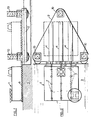
- Figure 1 schematically shows the transfer phase of a complete equipment 1, mounted and received ashore, on a self-elevating platform 2.
- the self-elevating platform is moored to platform 3 so that the transfer means provided on the deck of the platform are approximately in line with those of the platform.
- These transfer means consist respectively of paths 4 and sliding rails 5.
- the cradle 6, which forms part of the transfer means and which supports the equipment, consisting of living quarters, technical premises and possibly the drilling tower, is mounted on transfer supports constituted, for example, of five rows of three pads 7 also spaced according to what will be called the length of the cradle.
- the spacing of the pads on a row corresponds to the spacing of the rails 5 and the paths 4 of slip.
- the pads are mounted on flat cylinders so as to allow possible transfer of the loads from one row of pads to the other rows of pads as will be described later.
- a template 8 is provided which is placed between the platform 3 and the deck of the platform 2 This template carries guides 9 which connect the rails 5 to the paths 4.
- the transfer of the equipment takes place, in this example in a known manner, by sliding. But at this stage of the transport process any other means or method can be used and even possibly lifting by crane or gantry.
- the loading taking place in a generally calm coastal zone, does not present any particular difficulties.
- the self-elevating transport platform 2 is kept floating for receiving the load. It is not however excluded to make it rest on its feet 10.
- the load supported by the row of pads arriving on the template between the platform 3 and the platform 2 is transferred to the other rows of pads which rest either on the platform or on the jack-up platform.
- the jack-up platform 2 When the jack-up platform 2 is loaded, it is towed to the site and then stowed near the fixed platform 11.
- the platform 2 is positioned so as to approximate its transfer means in alignment with those provided on the platform 11 , then the bridge of the jack-up platform 2 is raised at the level of the bridge of the fixed platform 11.
- the two bridges are coupled by a guide frame 12 which has for function of maintaining the relative positions of the platforms relative to each other in the horizontal plane.
- the transfer of the load 1 is carried out from the jack-up platform 2 to the fixed platform 11, in a known manner, by sliding.
- the sliding paths 4 provided both on the fixed platform and on the self-elevating platform are relatively wide compared to the pads 7 of the cradle 6 carrying the load. This allows a transverse offset of the module during transfer due, for example, to a positioning defect of the paths of the two bridges, an offset which is easily compensated for during sliding.
- Changing the destination of the fixed platform is easily achievable by transferring, using the same process, the equipment from the bridge of the fixed platform to the bridge of the jack-up platform and replacing it during a subsequent transfer by equipment adapted to the new use of the fixed platform.
Landscapes
- Engineering & Computer Science (AREA)
- Mechanical Engineering (AREA)
- General Engineering & Computer Science (AREA)
- Civil Engineering (AREA)
- Structural Engineering (AREA)
- Chemical & Material Sciences (AREA)
- Combustion & Propulsion (AREA)
- Ocean & Marine Engineering (AREA)
- Architecture (AREA)
- Transportation (AREA)
- Bridges Or Land Bridges (AREA)
- Ship Loading And Unloading (AREA)
- Auxiliary Methods And Devices For Loading And Unloading (AREA)
- Conveying And Assembling Of Building Elements In Situ (AREA)
- Types And Forms Of Lifts (AREA)
- Refuse Collection And Transfer (AREA)
- Vehicle Body Suspensions (AREA)
- Tires In General (AREA)
Abstract
Description
L'invention concerne un procédé de transport et de transfert d'une charge constituée d'un équipement complet d'un pont de plate-forme marine fixe consistant à monter la totalité des installations d'un pont dans un chantier à terre, à transférer l'équipement complet sur des moyens de transport remorqués sur le site et à transférer ledit équipement sur le pont de la plate-forme à équiper.The invention relates to a method for transporting and transferring a load consisting of complete equipment for a fixed marine platform bridge, consisting in mounting all the installations of a bridge in a shore yard, to be transferred complete equipment on means of transport towed to the site and to transfer said equipment to the deck of the platform to be equipped.
L'infrastructure des plates-formes est généralement construite à terre, en une ou plusieurs parties qui sont remorquées sur le site, assemblées, puis immergées par contrôle de leur flottabilité. Le pont est ensuite équipé des installations correspondant à la destination de la plate-forme. Ces installations sont réalisées à partir de modules de poids et de dimensions standards, qui sont assemblés les uns aux autres in situ. Dans les mers à conditions climatiques normales, le levage et la mise en place des modules sont réalisés par des grues barges et des engins semi-submersibles classiques. Par contre l'utilisation de ces mêmes engins dans des mers aux conditions climatiques difficiles ne permet pas une efficacité suffisante pendant les très courtes périodes où les conditions atmosphériques autorisent le travail dans des conditions de sécurité suffisantes. Afin de diminuer les temps nécessaires au levage et à la mise en place des éléments et par conséquent de diminuer les risques climatiques, ainsi que les coûts de manutention et autres dépenses directes, on a cherché à augmenter la capacité de levage des grues barges et des semi-submersibles mais l'on a atteint une limite au-delà de laquelle les engins sont si coûteux que leur rentabilité ne peut être obtenue que par un taux d'utilisation journalier important. Malheureusement l'amortissement de ces engins ne peut être envisagé que sur quelques projets.The infrastructure of the platforms is generally built on the ground, in one or more parts which are towed on the site, assembled, then submerged by checking their buoyancy. The bridge is then equipped with the installations corresponding to the destination of the platform. These installations are made from modules of standard weights and dimensions, which are assembled together in situ. In seas with normal climatic conditions, the lifting and the installation of the modules are carried out by barge cranes and conventional semi-submersible machines. On the other hand, the use of these same devices in seas with difficult climatic conditions does not allow a sufficient efficiency during the very short periods when the atmospheric conditions authorize the work in conditions of sufficient safety. In order to reduce the time required to lift and install the elements and therefore to reduce the climatic risks, as well as the handling costs and other direct expenses, we sought to increase the lifting capacity of barge cranes and semi-submersible but a limit has been reached beyond which the machines are so expensive that their profitability can only be obtained by a high rate of daily use. Unfortunately the depreciation of these machines cannot only be considered on a few projects.
Il subsiste en outre des inconvénients sérieux dus aux procédés employés, ainsi les risques, inhérents à tout levage en mer, augmentent proportionnellement au poids levé, de même que ceux dûs au transfert d'une charge d'un engin flottant à une installation fixe.There are also serious drawbacks due to the methods used, so the risks inherent in any lifting at sea increase proportionally to the weight lifted, as well as those due to the transfer of a load from a floating object to a fixed installation.
Le temps nécessaire à l'installation des équipements, à leur essai et à leur réception n'en est pas pour cela diminué.The time required to install the equipment, to test it and to receive it is not therefore reduced.
L'installation fait appel à un grand nombre de personnes qui doivent s'accomoder de conditions d'habitat difficiles aggravées par les conditions climatiques.The installation appeals to a large number of people who have to live with difficult housing conditions made worse by climatic conditions.
Une solution à ces problèmes a été trouvée pour certaines plates-formes, et en particulier pour des plates-formes à embase poids et des plates-formes autoélévatrices, consistant à faire l'installation complète du pont ainsi que la réception du matériel dans le chantier de construction et à remorquer sur le site l'ensemble plate-forme et pont installé.A solution to these problems has been found for certain platforms, and in particular for weight-bearing platforms and jack-up platforms, consisting in making the complete installation of the bridge as well as the reception of the material on the site. of construction and to tow the installed platform and bridge assembly on site.
Ce mode de construction limite les possibilités d'utilisation de la plate-forme à celles initialement prévues et la transformation, par exemple, d'une plate-forme de forage en plate-forme de production n'est pas envisageable de manière simple, une bonne partie des installations devant être démontée et remplacée.This construction method limits the possibilities of using the platform to those initially planned and the transformation, for example, of a drilling platform into a production platform is not possible in a simple way, a a good part of the installations must be dismantled and replaced.
Le procédé, selon l'invention, vise à permettre le transfert de la totalité des équipements nécessaires à l'aménagement du pont d'une plate-forme dont l'infrastructure est déjà en place sur le site, les équipements étant montés et ayant subi la réception finale sur un chantier à terre.The method according to the invention aims to allow the transfer of all the equipment necessary for fitting out the bridge of a platform whose infrastructure is already in place on the site, the equipment being mounted and having undergone final acceptance on a shore site.
Selon l'invention, le transport et le transfert des équipements sont réalisés à partir d'une plate-forme autoélévatrice susceptible d'être reliée pour le chargement ou le déchargement au quai d'embarquement et à la plate-forme à équiper.According to the invention, the transport and transfer of the equipment is carried out from a self-elevating platform capable of being connected for loading or unloading to the embarkation platform and to the platform to be equipped.
Les explications et figures données ci-après à titre d'exemple permettront de comprendre comment l'invention peut être réalisée.
- La figure 1 représente la phase de transfert de l'équipement d'un quai à une plate-forme auto- élévatrice.
- La figure 2 est une vue de dessus de la figure 1 montrant une partie des moyens de transfert.
- La figure 3 représente la phase de transfert de l'équipement d'une plate-forme autoélévatrice à la plate-forme à équiper.
- FIG. 1 represents the phase of transferring the equipment from a quay to a jack-up platform.
- Figure 2 is a top view of Figure 1 showing part of the transfer means.
- FIG. 3 represents the phase of transfer of the equipment from a jack-up platform to the platform to be equipped.
La figure 1 montre schématiquement la phase de transfert d'un équipement complet 1, monté et réceptionné à terre, sur une plate-forme 2 autoélévatrice. De manière connue, la plate-forme autoélévatrice est amarrée au quai 3 de manière que les moyens de transfert prévus sur le pont de la plate-forme soient approximativement dans le prolongement de ceux du quai. Ces moyens de transfert sont constitués respectivement de chemins 4 et de rails 5 de glissement. Le berceau 6, qui forme une partie des moyens de transfert et qui supporte l'équipement, constitué des locaux d'habitation, des locaux techniques et éventuellement de la tour de forage, est monté sur des supports de transfert constitués, par exemple, de cinq rangées de trois patins 7 également espacées selon ce que l'on conviendra d'appeler la longueur du berceau. L'espacement des patins sur une rangée correspond à l'espacement des rails 5 et des chemins 4 de glissement. Les patins sont montés sur des vérins plats de manière à permettre éventuellement un transfert des charges d'une rangée de patins aux autres rangées de patins comme il sera ultérieurement décrit.Figure 1 schematically shows the transfer phase of a
Afin d'assurer l'alignement au moins approximatif entre les rails 5 et les chemins 4 de glissement de la plate-forme, il est prévu un gabarit 8 que l'on dispose entre le quai 3 et le pont de la plate-forme 2. Ce gabarit porte des guides 9 qui relient les rails 5 aux chemins 4.In order to ensure at least approximate alignment between the rails 5 and the sliding tracks 4 of the platform, a template 8 is provided which is placed between the
Le transfert de l'équipement s'opère, dans cet exemple de manière connue, par glissement. Mais à ce stade du procédé de transport tous autres moyens ou méthodes peuvent être utilisés et même éventuellement le levage par grue ou portique. Le chargement, s'opérant en zone côtière généralement calme, ne présente pas de difficultés particulières.The transfer of the equipment takes place, in this example in a known manner, by sliding. But at this stage of the transport process any other means or method can be used and even possibly lifting by crane or gantry. The loading, taking place in a generally calm coastal zone, does not present any particular difficulties.
La plate-forme autoélévatrice 2 de transport est maintenue en flottaison pour la réception de la charge. Il n'est toutefois pas exclu de la faire reposer sur ses pieds 10.The self-elevating
Dans le transfert par glissement, on évite que le gabarit 8 disposé entre le quai et la plate-forme ne supporte de charge.In the transfer by sliding, it is avoided that the template 8 disposed between the platform and the platform does not support a load.
Pour ce faire, la charge supportée par la rangée de patins arrivant sur le gabarit entre le quai 3 et la plate-forme 2, est transférée aux autres rangées de patins qui reposent soit sur le quai, soit sur la plate-forme autoélévatrice.To do this, the load supported by the row of pads arriving on the template between the
Lorsque la plate-forme autoélévatrice 2 est chargée, elle est remorquée sur le site puis arrimée près de la plate-forme fixe 11.When the jack-up
On positionne la plate-forme 2 de manière à mettre approximativement ses moyens de transfert en alignement avec ceux prévus sur la plate-forme 11, puis on lève le pont de la plate-forme autoélévatrice 2 au niveau du pont de la plate-forme fixe 11. On accouple les deux ponts par un châssis de guidage 12 qui a pour fonction de maintenir les positions relatives des plates-formes l'une par rapport à l'autre dans le plan horizontal.The
On opère le transfert de la charge 1, de la plate-forme autoélévatrice 2 à la plate-forme fixe 11, de manière connue, par glissement.The transfer of the
La rangée de patins s'engageant sur le châssis 12 entre les deux plates-formes est délestée de la charge au profit des autres rangées de patins reposant sur l'un ou les deux ponts,The row of skids engaging on the
Lorsque le transfert de la charge est terminé, les deux ponts sont désaccouplés par retrait du châssis de guidage 12.When the transfer of the load is complete, the two bridges are uncoupled by removing the
On met la plate-forme autoélévatrice en flottaison en remontant ses pieds et on en dispose en vue d'autres utilisations et notamment celle-ci peut être équipée d'une grue et de quartier d'habitation de façon à exécuter éventuellement la fin des travaux.We put the self-lifting platform in flotation by raising our feet and we have it for other uses and in particular it can be equipped with a crane and living quarters so as to eventually carry out the end of the work .
Il est à remarquer que les chemins de glissement 4 prévus aussi bien sur la plate-forme fixe que sur la plate-forme autoélévatrice sont relativement larges par rapport aux patins 7 du berceau 6 portant la charge. Ceci permet un décalage transversal du module lors du transfert dû, par exemple, à un défaut de positionnement des chemins des deux ponts, décalage qui est facilement rattrapable lors du glissement.It should be noted that the sliding paths 4 provided both on the fixed platform and on the self-elevating platform are relatively wide compared to the
La modification de destination de la plate-forme fixe est aisément réalisable en tranéférant, selon le même procédé, l'équipement du pont de la plate-forme fixe au pont de la plate-forme autoélévatrice et en le remplaçant lors d'un transfert ultérieur par un équipement adapté à la nouvelle utilisation de la plate-forme fixe.Changing the destination of the fixed platform is easily achievable by transferring, using the same process, the equipment from the bridge of the fixed platform to the bridge of the jack-up platform and replacing it during a subsequent transfer by equipment adapted to the new use of the fixed platform.
Claims (4)
Priority Applications (1)
| Application Number | Priority Date | Filing Date | Title |
|---|---|---|---|
| AT86400882T ATE41388T1 (en) | 1985-04-24 | 1986-04-23 | METHOD OF TRANSPORTING AND TRANSFERRING A HEAVY LOAD AT SEA TO A FIXED STRUCTURE. |
Applications Claiming Priority (2)
| Application Number | Priority Date | Filing Date | Title |
|---|---|---|---|
| FR8506232A FR2581020A1 (en) | 1985-04-24 | 1985-04-24 | METHOD FOR TRANSPORTING AND TRANSFERRING A LOAD CONSTITUTING A COMPLETE EQUIPMENT OF A BRIDGE OF A MARINE PLATFORM AND MEANS FOR IMPLEMENTING THE PROCESS |
| FR8506232 | 1985-04-24 |
Publications (2)
| Publication Number | Publication Date |
|---|---|
| EP0204591A1 true EP0204591A1 (en) | 1986-12-10 |
| EP0204591B1 EP0204591B1 (en) | 1989-03-15 |
Family
ID=9318625
Family Applications (1)
| Application Number | Title | Priority Date | Filing Date |
|---|---|---|---|
| EP86400882A Expired EP0204591B1 (en) | 1985-04-24 | 1986-04-23 | Method of transporting and transferring at sea a heavy load to a fixed structure |
Country Status (7)
| Country | Link |
|---|---|
| US (1) | US4826355A (en) |
| EP (1) | EP0204591B1 (en) |
| AT (1) | ATE41388T1 (en) |
| DE (1) | DE3662370D1 (en) |
| FR (1) | FR2581020A1 (en) |
| NO (1) | NO162656C (en) |
| WO (1) | WO1986006340A1 (en) |
Cited By (4)
| Publication number | Priority date | Publication date | Assignee | Title |
|---|---|---|---|---|
| GB2237834A (en) * | 1989-10-31 | 1991-05-15 | Transworld Drilling Co | System for moving drilling module to fixed off-shore platform |
| WO1992008007A1 (en) * | 1990-11-06 | 1992-05-14 | Rowan Companies, Inc. | Method and apparatus for transferring a drilling apparatus from a movable vessel to a fixed structure |
| US5290128A (en) * | 1990-11-06 | 1994-03-01 | Rowan Companies, Inc. | Method and apparatus for transferring a drilling apparatus from a movable vessel to a fixed structure |
| US5419657A (en) * | 1992-05-08 | 1995-05-30 | Rowan Companies, Inc. | Method and apparatus for transferring a structure from a jack-up rig to a fixed platform |
Families Citing this family (17)
| Publication number | Priority date | Publication date | Assignee | Title |
|---|---|---|---|---|
| NO165910C (en) * | 1988-06-16 | 1991-05-02 | Per Tybring Aralt | PROCEDURE AND DEVICE FOR TRANSPORTING HEAVY PACKAGES. |
| US5097786A (en) * | 1988-09-27 | 1992-03-24 | Sheffield Woodrow W | Method and apparatus for erecting and removing offshore structures |
| US5139367A (en) * | 1989-10-31 | 1992-08-18 | Transworld Drilling Co. | System for moving drilling module to fixed platform |
| US4973198A (en) * | 1989-12-28 | 1990-11-27 | Shell Oil Company | Offshore drilling rig transfer |
| AU4025593A (en) * | 1992-04-06 | 1993-11-08 | Rowan Companies, Inc. | Method and apparatus for transporting and using a drilling apparatus or a crane apparatus from a single movable vessel |
| US5558468A (en) * | 1994-07-15 | 1996-09-24 | Andrew C. Barnett, Jr. | Method and apparatus for erecting a marine structure |
| NL1016859C2 (en) * | 2000-12-13 | 2002-06-14 | Marine Construct B V | Method and device for placing at least one windmill on open water. |
| US6718901B1 (en) * | 2002-11-12 | 2004-04-13 | Technip France | Offshore deployment of extendable draft platforms |
| EP2091808B1 (en) * | 2006-11-22 | 2013-10-16 | Technip France | Structure for the transport, installation and dismantling of an oil rig deck and method for using one such structure |
| FR2923454B1 (en) * | 2007-11-09 | 2010-01-15 | Freyssinet | METHOD OF TRANSPORTING AQUATIC ENVIRONMENT OF A CIVIL WORK |
| IT1400399B1 (en) * | 2009-07-17 | 2013-05-31 | In Novo D O O | SELF-LIFTING PONTOON |
| DE202012004349U1 (en) * | 2012-05-04 | 2013-08-05 | Olb Offshore Logistics Bremerhaven Gmbh | Pontoon for transporting large and heavy loads |
| CN102849185B (en) * | 2012-09-18 | 2015-01-21 | 中国石油集团渤海石油装备制造有限公司 | Pile leg installation method for self-elevating drilling platform |
| EP3842367A3 (en) * | 2015-03-04 | 2021-09-29 | Shibakai Co., Ltd. | Cargo handling method |
| CN107687163B (en) * | 2016-08-05 | 2019-11-01 | 中集海洋工程研究院有限公司 | The wearing plate replacing options of jack-up unit cantilever beam |
| CN112319731A (en) * | 2020-11-20 | 2021-02-05 | 天津博迈科海洋工程有限公司 | Installation method of large-scale marine equipment |
| CN113338223B (en) * | 2021-06-09 | 2022-09-20 | 上海振华重工(集团)股份有限公司 | Method for adjusting unloading load |
Citations (3)
| Publication number | Priority date | Publication date | Assignee | Title |
|---|---|---|---|---|
| US4055264A (en) * | 1975-08-04 | 1977-10-25 | Brown & Root, Inc. | Deck section loading |
| GB2022521A (en) * | 1978-05-29 | 1979-12-19 | Scheepvaartbedrijf Con Brio Nv | A dockship |
| EP0094434A1 (en) * | 1981-11-25 | 1983-11-23 | Hitachi Zosen Corporation | Work ship for installing large offshore structure |
Family Cites Families (7)
| Publication number | Priority date | Publication date | Assignee | Title |
|---|---|---|---|---|
| US2997852A (en) * | 1954-12-30 | 1961-08-29 | De Long Corp | Apparatus and method for reecting a supporting structure over a body of water |
| FR1214760A (en) * | 1958-02-03 | 1960-04-12 | Bataafsche Petroleum | Method for removing a platform from a support device placed in water or for setting it there and installation for performing this method |
| NL135005C (en) * | 1967-10-11 | 1972-09-15 | ||
| FR2405182A1 (en) * | 1977-10-04 | 1979-05-04 | Metalliques Entrepr Cie Fse | PROCESS AND EQUIPMENT FOR PLACING ON COLUMNS ANCHORED TO THE BOTTOM, FROM A TRANSPORTER VESSEL, LOADS, PLATFORMS OR SIMILAR, FOR INSTALLATIONS OFF THE COAST |
| FR2514317A1 (en) * | 1981-10-12 | 1983-04-15 | Doris Dev Richesse Sous Marine | ADJUSTABLE FLOATABLE LOAD LIFTING AND TRANSPORTING DEVICE FOR WORKS AT SEA AND METHOD FOR THE IMPLEMENTATION OF SAID DEVICE |
| JPS5878296U (en) * | 1981-11-24 | 1983-05-26 | 日立造船株式会社 | Work boat for installing large offshore structures |
| JPS6054454B2 (en) * | 1982-11-17 | 1985-11-30 | 日立造船株式会社 | How to transport large offshore structures |
-
1985
- 1985-04-24 FR FR8506232A patent/FR2581020A1/en not_active Withdrawn
-
1986
- 1986-04-23 EP EP86400882A patent/EP0204591B1/en not_active Expired
- 1986-04-23 AT AT86400882T patent/ATE41388T1/en active
- 1986-04-23 DE DE8686400882T patent/DE3662370D1/en not_active Expired
- 1986-04-23 WO PCT/FR1986/000138 patent/WO1986006340A1/en not_active Ceased
- 1986-12-19 NO NO865171A patent/NO162656C/en unknown
-
1988
- 1988-08-30 US US07/239,007 patent/US4826355A/en not_active Expired - Fee Related
Patent Citations (3)
| Publication number | Priority date | Publication date | Assignee | Title |
|---|---|---|---|---|
| US4055264A (en) * | 1975-08-04 | 1977-10-25 | Brown & Root, Inc. | Deck section loading |
| GB2022521A (en) * | 1978-05-29 | 1979-12-19 | Scheepvaartbedrijf Con Brio Nv | A dockship |
| EP0094434A1 (en) * | 1981-11-25 | 1983-11-23 | Hitachi Zosen Corporation | Work ship for installing large offshore structure |
Non-Patent Citations (2)
| Title |
|---|
| PATENTS ABSTRACTS OF JAPAN, vol. 8, no. 201 (M-325)[1638], 14 septembre 1984; & JP - A - 59 91 209 (HITACHI ZOSEN K.K.) 25-05-1984 * |
| SHIPBUILDING AND SHIPPING RECORD, vol. 119, no. 19, 19 mai 1972, pages 29,30, Londres, GB; "A new concept for moving heavy loads" * |
Cited By (5)
| Publication number | Priority date | Publication date | Assignee | Title |
|---|---|---|---|---|
| GB2237834A (en) * | 1989-10-31 | 1991-05-15 | Transworld Drilling Co | System for moving drilling module to fixed off-shore platform |
| GB2237834B (en) * | 1989-10-31 | 1993-06-23 | Transworld Drilling Co | System for moving drilling module to fixed platform |
| WO1992008007A1 (en) * | 1990-11-06 | 1992-05-14 | Rowan Companies, Inc. | Method and apparatus for transferring a drilling apparatus from a movable vessel to a fixed structure |
| US5290128A (en) * | 1990-11-06 | 1994-03-01 | Rowan Companies, Inc. | Method and apparatus for transferring a drilling apparatus from a movable vessel to a fixed structure |
| US5419657A (en) * | 1992-05-08 | 1995-05-30 | Rowan Companies, Inc. | Method and apparatus for transferring a structure from a jack-up rig to a fixed platform |
Also Published As
| Publication number | Publication date |
|---|---|
| WO1986006340A1 (en) | 1986-11-06 |
| NO162656C (en) | 1990-01-31 |
| ATE41388T1 (en) | 1989-04-15 |
| NO162656B (en) | 1989-10-23 |
| NO865171L (en) | 1986-12-19 |
| US4826355A (en) | 1989-05-02 |
| FR2581020A1 (en) | 1986-10-31 |
| DE3662370D1 (en) | 1989-04-20 |
| EP0204591B1 (en) | 1989-03-15 |
Similar Documents
| Publication | Publication Date | Title |
|---|---|---|
| EP0204591B1 (en) | Method of transporting and transferring at sea a heavy load to a fixed structure | |
| EP1716293B1 (en) | Method and Device for dismanteling an oil platform | |
| EP0090006B1 (en) | Floating device and procedure for hoisting and transporting loads | |
| CN101903235A (en) | Method and barge system for installing an offshore wind turbine | |
| EP2454149A1 (en) | Catamaran ship used for assembling, transporting and installing a marine wind turbine on the seafloor | |
| AU2010206999A2 (en) | Preloading to reduce loads and save steel on topsides and grillage of catamaran systems | |
| EP3635180B1 (en) | Launching method | |
| SG193028A1 (en) | ||
| EP2516251A2 (en) | Pendular system for transporting a civil engineering structure in an aquatic medium | |
| FR2940244A1 (en) | GATEWAY FOR LOADING AND UNLOADING A ROAD SHIP | |
| FR2970748A1 (en) | Method for realizing maintenance operations i.e. replacement of heavier parts, of floating wind turbine device of off-shore wind energy production system, involves positioning floating wind turbine device on maintenance device | |
| EP4259927B1 (en) | Method for assembling a floating offshore wind farm | |
| FR3140065A1 (en) | Off-shore floating platform for manufacturing, assembly, maintenance and/or dismantling of floating wind turbines | |
| EP3144213A1 (en) | Method for installing an elongate element forming a wind turbine, in particular a wind-turbine tower | |
| RU2309221C2 (en) | Marine ice-resistant adjustable platform mounting system and method for platform transportation and mounting by means of mounting system | |
| FR2833922A1 (en) | Mounting heavy equipment onto floating vessel hull comprises fixing lifting units designed to work from seabed to ends of hanging equipment | |
| FR3047229A1 (en) | DEVICE FOR MOVING AND EARTHING A VESSEL | |
| EP0097069B1 (en) | Method for the installation of a platform in the sea, platform superstructure for carrying out this method | |
| EP2406489A1 (en) | System and method for submerging a hydraulic turbine engine | |
| US20240270356A1 (en) | Installation System and Method For An Offshore Wind Turbine | |
| FR2474992A1 (en) | Working float adjustable height - has vertical pillars supported on horizontal submerged containers bridged together | |
| FR3146305A1 (en) | Process for mass production of floats for offshore wind turbines | |
| CN121180389A (en) | Semi-submersible vessel and its operation | |
| CA1246940A (en) | Hook-up between a main body and a superstructure | |
| NO347364B1 (en) | Construction of offshore wind power plants |
Legal Events
| Date | Code | Title | Description |
|---|---|---|---|
| PUAI | Public reference made under article 153(3) epc to a published international application that has entered the european phase |
Free format text: ORIGINAL CODE: 0009012 |
|
| AK | Designated contracting states |
Kind code of ref document: A1 Designated state(s): AT BE CH DE FR GB IT LI LU NL SE |
|
| 17P | Request for examination filed |
Effective date: 19870218 |
|
| 17Q | First examination report despatched |
Effective date: 19871105 |
|
| GRAA | (expected) grant |
Free format text: ORIGINAL CODE: 0009210 |
|
| AK | Designated contracting states |
Kind code of ref document: B1 Designated state(s): AT BE CH DE FR GB IT LI LU NL SE |
|
| REF | Corresponds to: |
Ref document number: 41388 Country of ref document: AT Date of ref document: 19890415 Kind code of ref document: T |
|
| GBT | Gb: translation of ep patent filed (gb section 77(6)(a)/1977) | ||
| REF | Corresponds to: |
Ref document number: 3662370 Country of ref document: DE Date of ref document: 19890420 |
|
| PGFP | Annual fee paid to national office [announced via postgrant information from national office to epo] |
Ref country code: CH Payment date: 19890421 Year of fee payment: 4 |
|
| PGFP | Annual fee paid to national office [announced via postgrant information from national office to epo] |
Ref country code: FR Payment date: 19890426 Year of fee payment: 4 Ref country code: AT Payment date: 19890426 Year of fee payment: 4 |
|
| PGFP | Annual fee paid to national office [announced via postgrant information from national office to epo] |
Ref country code: SE Payment date: 19890428 Year of fee payment: 4 |
|
| PG25 | Lapsed in a contracting state [announced via postgrant information from national office to epo] |
Ref country code: LU Free format text: LAPSE BECAUSE OF NON-PAYMENT OF DUE FEES Effective date: 19890430 |
|
| PGFP | Annual fee paid to national office [announced via postgrant information from national office to epo] |
Ref country code: NL Payment date: 19890430 Year of fee payment: 4 |
|
| PGFP | Annual fee paid to national office [announced via postgrant information from national office to epo] |
Ref country code: DE Payment date: 19890519 Year of fee payment: 4 |
|
| PGFP | Annual fee paid to national office [announced via postgrant information from national office to epo] |
Ref country code: LU Payment date: 19890522 Year of fee payment: 4 |
|
| ITF | It: translation for a ep patent filed | ||
| PGFP | Annual fee paid to national office [announced via postgrant information from national office to epo] |
Ref country code: BE Payment date: 19890613 Year of fee payment: 4 |
|
| PLBE | No opposition filed within time limit |
Free format text: ORIGINAL CODE: 0009261 |
|
| STAA | Information on the status of an ep patent application or granted ep patent |
Free format text: STATUS: NO OPPOSITION FILED WITHIN TIME LIMIT |
|
| 26N | No opposition filed | ||
| PG25 | Lapsed in a contracting state [announced via postgrant information from national office to epo] |
Ref country code: GB Effective date: 19900423 Ref country code: AT Effective date: 19900423 |
|
| PG25 | Lapsed in a contracting state [announced via postgrant information from national office to epo] |
Ref country code: SE Effective date: 19900424 |
|
| ITTA | It: last paid annual fee | ||
| PG25 | Lapsed in a contracting state [announced via postgrant information from national office to epo] |
Ref country code: LI Effective date: 19900430 Ref country code: CH Effective date: 19900430 Ref country code: BE Effective date: 19900430 |
|
| BERE | Be: lapsed |
Owner name: MODULAR JACK-UP SYSTEMS CY INC. Effective date: 19900430 |
|
| PG25 | Lapsed in a contracting state [announced via postgrant information from national office to epo] |
Ref country code: NL Effective date: 19901101 |
|
| NLV4 | Nl: lapsed or anulled due to non-payment of the annual fee | ||
| GBPC | Gb: european patent ceased through non-payment of renewal fee | ||
| PG25 | Lapsed in a contracting state [announced via postgrant information from national office to epo] |
Ref country code: FR Effective date: 19901228 |
|
| REG | Reference to a national code |
Ref country code: CH Ref legal event code: PL |
|
| PG25 | Lapsed in a contracting state [announced via postgrant information from national office to epo] |
Ref country code: DE Effective date: 19910101 |
|
| REG | Reference to a national code |
Ref country code: FR Ref legal event code: ST |
|
| EUG | Se: european patent has lapsed |
Ref document number: 86400882.6 Effective date: 19910116 |
|
| PG25 | Lapsed in a contracting state [announced via postgrant information from national office to epo] |
Ref country code: IT Free format text: LAPSE BECAUSE OF NON-PAYMENT OF DUE FEES;WARNING: LAPSES OF ITALIAN PATENTS WITH EFFECTIVE DATE BEFORE 2007 MAY HAVE OCCURRED AT ANY TIME BEFORE 2007. THE CORRECT EFFECTIVE DATE MAY BE DIFFERENT FROM THE ONE RECORDED. Effective date: 20050423 |