EP0203533A2 - Verfahren zum Aufheizen von geschmolzenem Stahl mittels Lichtbogen - Google Patents
Verfahren zum Aufheizen von geschmolzenem Stahl mittels Lichtbogen Download PDFInfo
- Publication number
- EP0203533A2 EP0203533A2 EP86106973A EP86106973A EP0203533A2 EP 0203533 A2 EP0203533 A2 EP 0203533A2 EP 86106973 A EP86106973 A EP 86106973A EP 86106973 A EP86106973 A EP 86106973A EP 0203533 A2 EP0203533 A2 EP 0203533A2
- Authority
- EP
- European Patent Office
- Prior art keywords
- gas
- molten steel
- electrode
- arc
- inert gas
- Prior art date
- Legal status (The legal status is an assumption and is not a legal conclusion. Google has not performed a legal analysis and makes no representation as to the accuracy of the status listed.)
- Granted
Links
Images




Classifications
-
- C—CHEMISTRY; METALLURGY
- C21—METALLURGY OF IRON
- C21C—PROCESSING OF PIG-IRON, e.g. REFINING, MANUFACTURE OF WROUGHT-IRON OR STEEL; TREATMENT IN MOLTEN STATE OF FERROUS ALLOYS
- C21C7/00—Treating molten ferrous alloys, e.g. steel, not covered by groups C21C1/00 - C21C5/00
-
- C—CHEMISTRY; METALLURGY
- C21—METALLURGY OF IRON
- C21C—PROCESSING OF PIG-IRON, e.g. REFINING, MANUFACTURE OF WROUGHT-IRON OR STEEL; TREATMENT IN MOLTEN STATE OF FERROUS ALLOYS
- C21C5/00—Manufacture of carbon-steel, e.g. plain mild steel, medium carbon steel or cast steel or stainless steel
- C21C5/52—Manufacture of steel in electric furnaces
-
- C—CHEMISTRY; METALLURGY
- C21—METALLURGY OF IRON
- C21C—PROCESSING OF PIG-IRON, e.g. REFINING, MANUFACTURE OF WROUGHT-IRON OR STEEL; TREATMENT IN MOLTEN STATE OF FERROUS ALLOYS
- C21C7/00—Treating molten ferrous alloys, e.g. steel, not covered by groups C21C1/00 - C21C5/00
- C21C7/0075—Treating in a ladle furnace, e.g. up-/reheating of molten steel within the ladle
-
- C—CHEMISTRY; METALLURGY
- C21—METALLURGY OF IRON
- C21C—PROCESSING OF PIG-IRON, e.g. REFINING, MANUFACTURE OF WROUGHT-IRON OR STEEL; TREATMENT IN MOLTEN STATE OF FERROUS ALLOYS
- C21C7/00—Treating molten ferrous alloys, e.g. steel, not covered by groups C21C1/00 - C21C5/00
- C21C7/04—Removing impurities by adding a treating agent
- C21C7/072—Treatment with gases
-
- C—CHEMISTRY; METALLURGY
- C21—METALLURGY OF IRON
- C21C—PROCESSING OF PIG-IRON, e.g. REFINING, MANUFACTURE OF WROUGHT-IRON OR STEEL; TREATMENT IN MOLTEN STATE OF FERROUS ALLOYS
- C21C7/00—Treating molten ferrous alloys, e.g. steel, not covered by groups C21C1/00 - C21C5/00
- C21C7/0056—Treating molten ferrous alloys, e.g. steel, not covered by groups C21C1/00 - C21C5/00 using cored wires
-
- Y—GENERAL TAGGING OF NEW TECHNOLOGICAL DEVELOPMENTS; GENERAL TAGGING OF CROSS-SECTIONAL TECHNOLOGIES SPANNING OVER SEVERAL SECTIONS OF THE IPC; TECHNICAL SUBJECTS COVERED BY FORMER USPC CROSS-REFERENCE ART COLLECTIONS [XRACs] AND DIGESTS
- Y02—TECHNOLOGIES OR APPLICATIONS FOR MITIGATION OR ADAPTATION AGAINST CLIMATE CHANGE
- Y02P—CLIMATE CHANGE MITIGATION TECHNOLOGIES IN THE PRODUCTION OR PROCESSING OF GOODS
- Y02P10/00—Technologies related to metal processing
- Y02P10/20—Recycling
Definitions
- the present invention relates to a method of heating molten steel by an arc process, wherein an arc is formed between molten steel and electrodes dipped in slag on molten steel contained in a ladle.
- the converter tap temperature of the molten steel can be decreased, thereby leading to a decrease in the required amounts of converter refractory and auxiliary materials.
- the yield of molten steel tapped from the converter can thus be increased.
- molten steel is tapped from a converter into a ladle, and carbon electrodes are dipped into slag on the molten steel. An arc is formed between the molten steel and each electrode while the electrodes are surrounded by the slag.
- nitrogen gas is, however, present in the ladle during arc heating, it is absorbed by the molten steel, increasing the nitrogen concentration [N] in molten steel, thus causing the nitrogen pickup phenomenon.
- argon gas is blown into the ladle or into work holes into the cover of a conventional ladle, thereby sealing the molten steel off from any nitrogen gas present.
- a method of heating molten steel by an arc process comprising the steps of: dipping a lower end portion of an electrode into slag on molten steel contained in a ladle; energizing the electrode to form an arc between the electrode and the molten steel, the electrode having a gas injection port formed at the lower end thereof, a gas inlet port at the upper portion thereof, and a gas flow path connecting the gas injection port with the gas inlet port; and supplying an inert gas from a gas supply means to the gas inlet port of the electrode and injecting the inert gas from the gas injection port through the gas flow path.
- the present inventors have made extensive studies of the molten steel nitrogen pickup mechanism during the arc process, and have discovered the following facts: when nitrogen is present in an arc region between an electrode and the molten steel, nitrogen gas molecules (N 2 ) are activated as a plasma by the arc heat; atomic nitrogen (N) is thereby produced in the active region, and is absorbed by the molten steel, causing the nitrogen pickup phenomenon.
- molten steel 3 tapped from a converter is contained in ladle 1.
- Three electrodes 5 are charged in the ladle through holes formed in cover 2 thereof. The lower end portions of electrodes 5 are dipped into slag 4 on molten steel 3.
- Electrodes 5 are made of a carbon material.
- Each electrode 5 charged in ladle 1 is connected to three-phase AC power source 6.
- Gas flow paths 7 (illustrated for only one electrode) are formed in electrodes 5 along their longitudinal direction. Paths 7 are open at the upper and lower ends of electrodes 5.
- the lower opening of each electrode 5 constitutes gas injection port 8.
- the upper end of each electrode 5 is connected to hose 9, which is coupled to an appropriate inert gas source, such as Ar gas source 12.
- Gas flow control valve 10 and flow meter 11 are inserted midway along hose 9.
- Porous plugs 13 are mounted in the bottom surface of ladle 1. Plugs 13 are connected to pipe 14, which is also coupled to an Ar gas source (not shown). Inert gas (Ar gas), to stir the molten steel 3, is supplied through plugs 13.
- Ar gas Ar gas
- molten steel 3 is tapped from the converter into ladle 1 and electrodes 5 are dipped into slag 4 on molten steel 3. Electrodes 5 are energized to form an arc between electrodes 5 and molten steel 3, thereby heating molten steel 3 with the arc.
- Ar gas is injected from ports 8 at the lower ends of electrodes 5 at a flow rate of 21 Nm 3 /h (350 N A/min) to fill the arc region with Ar gas.
- the inert (Ar) gas is injected from ports 8 of electrodes 5 to fill the arc region with the inert gas, so as to eliminate nitrogen gas from there. Nitrogen gas is therefore not activated, effectively preventing the nitrogen pickup phenomenon.
- Fig. 2 shows the effect of the hollow electrodes which decrease the amount of nitrogen pickup.
- the process time (energizing time) of the arc process is plotted along the abscissa and the nitrogen pickup amount (ppm) is plotted along the ordinate.
- the graph in Fig. 2 shows increments in nitrogen concentration in molten steel.
- White dots represent increments when conventional solid electrodes are used.
- Black dots and triangles represent increments when Ar gas is injected from the gas injection ports of the hollow electrodes. More specifically, the Ar gas flow rate is 18 Nm 3 /h or more for the black dots and less than 18 Nm 3 /h for the black triangles.
- the nitrogen pickup amount tends to increase as the process time is prolonged.
- the nitrogen pickup amount is 5 ppm or less, compared to a maximum of 14 ppm for the conventional solid electrodes (the region surrounded by the solid line).
- the nitrogen pickup amount is increased in relation to the prolongation of the process time, and the nitrogen concentration range is undesirably wide.
- Molten steel tapped from a 290-ton converter was arc-heated using an Ar gas flow rate of 18 Nm 3 /h through hollow electrodes, each having a gas flow path diameter of 20 mm.
- the nitrogen concentration prior to arc heating was 30 ppm, and arc-heated molten steel contained 33 ppm of nitrogen. Therefore, the nitrogen pickup amount could be decreased to 3 ppm.
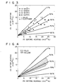
- Fig. 3 is a graph obtained when Ar gas is injected through electrodes 5 to stir slag 4 and molten steel 3 addition to Ar injection from plugs 13 at the bottom of ladle 1.
- the concentration of sulfur [S] in the molten steel prior to this process is plotted along the abscissa and that after the process is plotted along the ordinate.
- the results, using hollow electrodes, are compared with those using solid electrodes.
- Ar gas flow rates for each electrode were 6, 12, 18, and 24 Nm 3 /h.
- the sulfur concentrations obtained by using the conventional solid electrodes are also plotted for reference. A hatched region in Fig.
- FIG. 4 shows a case wherein deoxidized molten steel was stirred by gas supplied from plugs 13 at the bottom of ladle 1.
- a crosshatched region in Fig. 4 shows a case wherein molten steel was stirred by the gas from plugs 13 at the bottom of ladle 1 as well as gas provided through electrodes 5.
- the desulfurization rate was about 50%.
- the desulfurization rate using the hollow electrodes of the first embodiment was about 60%.
- the total content of aluminum in the deoxidized molten steel was 0.025% or more.
- the slag temperature is not higher than that of the molten steel.
- energizing was stopped for 1 to 2 minutes (performing only bubbling of the molten steel) to allow the slag to cool.
- energizing was resumed.
- continuous energizing can be achieved.
- the conventional arc heating cycle requires about 40 minutes, the process time was shortened to about 30 minutes using the structure of this embodiment.
- the inert gas above is exemplified by Ar gas, but can also be xenon (Xe) gas or the like.
- each hollow electrode only one gas flow path is formed in each hollow electrode.
- a plurality of gas flow paths of a small diameter may be formed.
- a plurality of gas injection holes connected with the gas flow path may be formed at the distal end of each electrode.
- Slag thickness at the start of arc heating is usually about 30 mm.
- Ar gas in order to decrease the nitrogen pickup rate in molten steel to 0.04 ppm/min or less, Ar gas must be injected from ports 8 of electrodes 5 at a flow rate of 350 NX/min for each electrode.
- arc heating progresses at the same time as a flux is added to molten steel to refine the molten steel with the slag. For this reason, the thickness of slag 4 on molten steel 3 is increased over time.
- a bare molten steel region, formed by eliminating slag through arcs formed between the electrodes and the molten steel is decreased.
- the slag region covering the molten steel is increased.
- the molten steel surface area subjected to permeation of nitrogen molecules or atoms is thus decreased.
- the flow rate of Ar gas injected through gas injection ports 8 to prevent the nitrogen pickup phenomenon can be decreased.
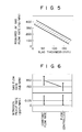
- Fig. 5 is a graph obtained by plotting Ar gas flow rate as a function of slag thickness when the molten steel nitrogen pickup rate is 0.04 ppm/min. As is apparent frpm Fig. 5, when the slag thickness is increased, the Ar gas flow rate is decreased. When the slag thickness is 140 mm or 160 mm, the Ar gas flow rate for keeping the nitrogen pickup rate at 0.04 ppm/min is 150 Ni/min or 100 Ni/min.
- the flow rate of Ar gas injected from hollow electrodes 5 can be decreased as the slag thickness on the molten steel increases, thereby preventing excess consumption of Ar gas.
- the slag thickness can be continuously measured by an eddy current sensor.
- a probe rod may be inserted in slag prior to arc heating to measure the slag thickness by measuring the length of a portion of the slag that becomes attached to the probe rod. After the slag is charged in the ladle, an increment of slag thickness upon melting of the flux is calculated from the weight of the flux charged in the ladle. This increment is added to the original slag thickness to obtain a total slag thickness.
- the Ar gas flow rate can be automatically controlled using a microcomputer or the like.
- flow meter 11 can perform monitoring, on the basis of the relationship shown in Fig. 5, to control the opening of valve 10 and thereby correct Ar gas flow rate.
- the maximum flow rate of Ar gas injected from each hollow electrode is 350 Ni/min.
- the Ar gas flow rate can be greatly decreased.
- the flow rate of Ar gas injected from the hollow electrodes is sequentially decreased as slag thickness increases.
- the average flow rate of Ar gas can be reduced to 150 Ni/min.
- Ar gas consumption can thus be decreased.
- the Ar gas flow rate can be decreased to 3% of that of the conventional method.
- the nitrogen pickup phenomenon of molten steel can be effectively prevented even if the amount of inert gas is small.
- the flow rate of the inert gas can be decreased upon an increase in slag thickness, thereby preventing excess use of the inert gas and thus decreasing inert gas consumption.
- a third embodiment of the present invention is described in detail below.
- a powder mixture of chromium ore and carbon material is carried in Ar gas and is sprayed through electrodes to add chromium to molten steel.
- chromium ore is charged in molten steel tapped into a ladle.
- the temperature of the molten steel is then increased to react chromium ore (Cr 2 0 3 ) with Ai or Si, thereby adding reaction product of chromium to the molten steel.
- the third embodiment can also solve this conventional problem.
- hose 9 One end of hose 9 is connected to the upper end of electrode 5.
- the other end of hose 9 is connected to pipe 15 for supplying chromium ore and carbon material as a reducing agent together with a carrier gas.
- Pipe 15 is coupled to Ar gas source 12.
- a carbon powder hopper 16 and a chromium powder hopper 17 are arranged midway along pipe 15.
- Valve 18 is arranged at the bottom of hopper 16 and couples hopper 16 to pipe 15, to control the amount of carbon supplied thereto.
- valve 19 is arranged at the bottom of hopper 17, coupling it to pipe 15.
- Valve 19 controls the amount of chromium ore supplied to pipe 15.
- the powder mixture is carried by the (Ar) carrier gas, and is continuously injected toward molten steel 3 from injection port 8 at the distal and of electrode 5 through gas flow path 7.
- the powder mixture injected from port 8 reacts due to the heat (2 000 to 3 000°C) of the arc formed between the electrode and molten steel in the following manner: Cr203 + 3C + 2Cr + 3CO
- the reaction of the above formula is not easily effected in molten steel at conventional temperatures of 1 600 to 1 700°C due to a low free energy level, and the reaction rate is low. At such a low temperature, reduction of Cr 2 0 3 with carbon is impossible in practice. According to this embodiment, however, the arc temperature is 2 000 to 3 000°C, accelerating the above reaction, i.e., allowing easy reduction of Cr 2 0 3 with carbon.
- Fig. 8 is a graph showing chromium yield obtained with the above structure.
- the arc heating time (minutes) is plotted along the abscissa and the concentration [Cr] of chromium in molten steel is plotted along the ordinate.
- the mole ratio of carbon material to chromium ore was 3 : 1.
- a powder mixture of carbon and chromium ore was supplied at a rate of 93 kg/min for 20 minutes.
- the broken line in Fig. 8 represents changes in chromium concentration in molten steel at 100% yield (i.e., when the amount of Cr entering into the slag is zero).
- chromium ore can be reduced to add Cr into the molten steel at substantially 100% yield. It was also found that the reaction occurred quickly upon injection of the powder mixture. In addition, it is obvious that the chromium concentration in molten steel can be easily controlled via the amount of powder mixture injected in.
- Fig. 9 is a graph showing a percent reduction when the mole ratio of carbon to chromium ore is changed.
- the mole ratio of carbon to chromium ore is plotted along the abscissa and the percent reduction is plotted along the ordinate.
- the percent reduction linearly increases up to a mole ratio of 3.0.
- the mole ratio exceeds 3.0, the carbon content becomes excessive and the percent reduction thereafter is substantially constant. Therefore, if the mole ratio is set to be 3.0, a substantially 100% percent reduction can be achieved.
- carbon and chromium ore are independently stored in different hoppers and are mixed in the pipe.
- carbon may be premixed with chromium ore and the resultant mixture may be stored in a single hopper.
- the carbon and chromium hoppers need not be inserted in series on a single pipe, but can be arranged parallel to each other. In this case, the carrier gas for these different powders is supplied through two different pipes.
- inexpensive carbon is used in place of expensive A ⁇ or Si to reduce chromium ore, thereby adding chromium to molten steel and allowing a reduction in the process cost.
- flux for forming slag is mixed in Ar gas and the gas is injected through an electrode. The flux is thus melted to obtain slag by arc heat.
- flux is added to molten steel in a ladle, and an arc is formed between electrodes and the molten steel to heat the molten steel and the flux added thereon.
- the flux is thus melted to form the slag layer on the molten steel.
- flux is heated and melted in another furnace to obtain molten slag, and the slag is then added into the ladle.
- the lower portion of the flux layer is easily heated and melted.
- it takes a long time to melt the upper portion of the flux It took about 20 minutes to melt all the flux using the conventional method.
- the conventional arc process time is 40 minutes, half of the total process time is consumed by melting flux. Therefore, desulfurization time is not enough, shorteleading to low deoxidation/desulfurization efficiency.
- an alloy for adjusting the steel component is added to molten steel before the slag material is completely melted, the molten steel components vary undesirably. Using the latter method of melting the flux in a different furnace, an adequate slagging state can be maintained, but only at high cost.
- the fourth embodiment can also solve the above problems.
- hose 9 One end of hose 9 is connected to the upper end of electrode 5. The other end of hose 9 is connected to pipe 15 for supplying a slag material carried by Ar gas. Pipe 15 is connected to Ar gas source 12. The bottom portion of hopper 20 for storing a flux powder is coupled midway along pipe 15. Valve 21 is arranged at the bottom portion of hopper 20 to control the amount of the flux supplied to pipe 15. Valve 21 couples hopper 20 to pipe 15. Bypass 22 is formed between the upper portion of hopper 20 and the upstream portion of pipe 15 with respect to valve 21. Bypass 22 prevents a decrease in internal pressure of hopper 20 when the slag material is supplied from hopper 20.
- Electrode 5 is energized to form an arc between electrode 5 and molten steel 3, thereby arc-heating molten steel 3.
- Ar gas as a carrier gas is supplied to pipe 15, and valve 21 of the hopper is opened to supply the flux powder to gas flow path 7.
- the flux is carried by the Ar gas and is continuously injected from injection port 8 at the distal end of electrode 5 through path 7 toward molten steel 3.
- the flux powder injected from the distal end of the electrode is quickly melted and slagged by the heat (2 000 to 3 000°C) of the arc formed between the electrode and the molten steel, and by the heat of the molten steel.
- the slag is dispersed in the molten steel by the injection energy of the electrode, and is spread from the electrode region to form a slag layer on the molten steel.
- the slag layer is immediately formed on the molten steel.
- the heat from the molten steel and the arc process are utilized to melt the flux without requiring additional heating, thus reducing the process cost. Since the flux can be immediately slagged, desulfurization speed and rate upon the reaction between the slag and the molten steel can be improved.
- Flux powder (CaO of 200 meshes) was supplied to molten steel tapped from a 290-ton converter at a rate of 60 kg/min for 10 minutes.
- the electrode was hollow, having a gas flow path diameter of 20 mm.
- Ar gas was supplied at a rate of 500 L/min and a pressure of 5 kg/cm 3 .
- the results are indicated by black dots.
- the flux was added onto the molten steel to melt it by the heat of the molten steel, according to the conventional method. The results are indicated by white dots.
- Fig. 11 is a graph showing the desulfurization rate.
- the concentration [S] of sulfur in molten steel prior to arc heating is plotted along the abscissa and the concentration [S] of sulfur after arc heating is plotted along the ordinate.
- the desulfurization rate was 50 to 60%.
- the method of this embodiment provided a desulfurization rate of 70 to 80%.
- Fig. 12 is a graph showing the slagging rate of the slag material.
- the energizing time of the electrode is plotted along the abscissa and the sulfur concentration [S] in molten steel is plotted along the ordinate.
- the concentration [S] was decreased to about 10 x 10- 3 % within 20 minutes of energizing.
- black dots the concentration was decreased to about 10 x 10- 3 % within about 5 minutes, and to about 5 to 7 x 10 -3 % within 10 minutes.
- the melting rate of flux (indicated by the slope of the region) upon energizing the electrode is improved by about 30%.
- the flux is melted immediately to obtain a high desulfurization rate.
- the flux need not be slagged in a separate furnace or maintained at a predetermined temperature, and slagging can be performed by utilizing the heat in the ladle, resulting in a low process cost.
Landscapes
- Chemical & Material Sciences (AREA)
- Engineering & Computer Science (AREA)
- Materials Engineering (AREA)
- Metallurgy (AREA)
- Organic Chemistry (AREA)
- Manufacturing & Machinery (AREA)
- Treatment Of Steel In Its Molten State (AREA)
Applications Claiming Priority (8)
| Application Number | Priority Date | Filing Date | Title |
|---|---|---|---|
| JP60115940A JPS61272309A (ja) | 1985-05-29 | 1985-05-29 | ア−クプロセスにおける溶鋼の精錬方法 |
| JP115942/85 | 1985-05-29 | ||
| JP60115942A JPS61272310A (ja) | 1985-05-29 | 1985-05-29 | ア−クプロセスにおける造滓剤の滓化方法 |
| JP115940/85 | 1985-05-29 | ||
| JP60115943A JPS61276684A (ja) | 1985-05-29 | 1985-05-29 | 溶鋼のア−ク加熱方法 |
| JP115943/85 | 1985-05-29 | ||
| JP121731/85 | 1985-06-05 | ||
| JP60121731A JPS61279613A (ja) | 1985-06-05 | 1985-06-05 | ア−クプロセスにおける窒素のピツクアツプ防止方法 |
Publications (3)
| Publication Number | Publication Date |
|---|---|
| EP0203533A2 true EP0203533A2 (de) | 1986-12-03 |
| EP0203533A3 EP0203533A3 (en) | 1987-08-19 |
| EP0203533B1 EP0203533B1 (de) | 1991-01-23 |
Family
ID=27470304
Family Applications (1)
| Application Number | Title | Priority Date | Filing Date |
|---|---|---|---|
| EP86106973A Expired - Lifetime EP0203533B1 (de) | 1985-05-29 | 1986-05-22 | Verfahren zum Aufheizen von geschmolzenem Stahl mittels Lichtbogen |
Country Status (5)
| Country | Link |
|---|---|
| US (1) | US4650517A (de) |
| EP (1) | EP0203533B1 (de) |
| KR (1) | KR900004159B1 (de) |
| CA (1) | CA1242325A (de) |
| DE (1) | DE3677059D1 (de) |
Cited By (2)
| Publication number | Priority date | Publication date | Assignee | Title |
|---|---|---|---|---|
| EP0342374A1 (de) * | 1988-05-19 | 1989-11-23 | Nkk Corporation | Verfahren zur Schmelzreduktion im Elektro-Ofen |
| CN110551872A (zh) * | 2019-09-29 | 2019-12-10 | 山东钢铁股份有限公司 | 一种用于电弧炉冶炼低氮钢种的装置 |
Families Citing this family (2)
| Publication number | Priority date | Publication date | Assignee | Title |
|---|---|---|---|---|
| US5575829A (en) * | 1995-06-06 | 1996-11-19 | Armco Inc. | Direct use of sulfur-bearing nickel concentrate in making Ni alloyed stainless steel |
| CN102899456A (zh) * | 2012-09-25 | 2013-01-30 | 鞍钢股份有限公司 | 一种减少钢包精炼炉钢水升温增氮的方法 |
Family Cites Families (4)
| Publication number | Priority date | Publication date | Assignee | Title |
|---|---|---|---|---|
| US3708599A (en) * | 1971-04-22 | 1973-01-02 | Thermal Transfer Corp | High temperature apparatus |
| GB1384259A (en) * | 1972-02-01 | 1975-02-19 | Finkl & Sons Co | Method and apparatus for desulphurizing steel |
| US3854932A (en) * | 1973-06-18 | 1974-12-17 | Allegheny Ludlum Ind Inc | Process for production of stainless steel |
| SE449373B (sv) * | 1977-07-01 | 1987-04-27 | Dso Cherna Metalurgia | Sett och anordning for raffinering av jernbaserade smeltor i elektrisk reaktionsugn |
-
1986
- 1986-05-20 KR KR1019860003926A patent/KR900004159B1/ko not_active Expired
- 1986-05-22 EP EP86106973A patent/EP0203533B1/de not_active Expired - Lifetime
- 1986-05-22 DE DE8686106973T patent/DE3677059D1/de not_active Expired - Lifetime
- 1986-05-28 CA CA000510202A patent/CA1242325A/en not_active Expired
- 1986-05-29 US US06/868,807 patent/US4650517A/en not_active Expired - Fee Related
Cited By (2)
| Publication number | Priority date | Publication date | Assignee | Title |
|---|---|---|---|---|
| EP0342374A1 (de) * | 1988-05-19 | 1989-11-23 | Nkk Corporation | Verfahren zur Schmelzreduktion im Elektro-Ofen |
| CN110551872A (zh) * | 2019-09-29 | 2019-12-10 | 山东钢铁股份有限公司 | 一种用于电弧炉冶炼低氮钢种的装置 |
Also Published As
| Publication number | Publication date |
|---|---|
| KR900004159B1 (ko) | 1990-06-18 |
| US4650517A (en) | 1987-03-17 |
| CA1242325A (en) | 1988-09-27 |
| EP0203533B1 (de) | 1991-01-23 |
| EP0203533A3 (en) | 1987-08-19 |
| KR860009139A (ko) | 1986-12-20 |
| DE3677059D1 (de) | 1991-02-28 |
Similar Documents
| Publication | Publication Date | Title |
|---|---|---|
| CA1115759A (en) | Refining ferrous melt | |
| US20180202012A1 (en) | Method of making steel using a single installation, and installation | |
| RU2159819C2 (ru) | Способ и установка для обезуглероживания расплавов стали | |
| WO2012015642A2 (en) | A composition and process for improved efficiency in steel making | |
| US4650517A (en) | Method of heating molten steel by arc process | |
| CA2735470C (en) | Production of ferro-alloys | |
| US4198229A (en) | Method of dephosphorization of metal or alloy | |
| RU2405046C1 (ru) | Способ выплавки, раскисления, легирования и обработки стали | |
| US6068676A (en) | Method and apparatus for producing high chromium content steels and/ or ferroalloys in an electric arc converter | |
| US4806156A (en) | Process for the production of a bath of molten metal or alloys | |
| KR910009960B1 (ko) | 전기로의 용융환원법 | |
| RU2118376C1 (ru) | Способ производства ванадиевого шлака и природнолегированной ванадием стали | |
| CA2559154A1 (en) | Method for a direct steel alloying | |
| RU62048U1 (ru) | Установка печь-ковш | |
| JP3587887B2 (ja) | ステンレス鋼溶製時の吸窒防止法 | |
| JPH02407B2 (de) | ||
| RU2097434C1 (ru) | Способ выплавки стали в конвертере | |
| US4023962A (en) | Process for regenerating or producing steel from steel scrap or reduced iron | |
| US4052195A (en) | Method for melting iron-containing material | |
| SU1650716A1 (ru) | Способ внепечной обработки стали | |
| US4067729A (en) | Desulfurization of liquid iron melts | |
| RU2384627C1 (ru) | Способ выплавки стали в дуговой электросталеплавильной печи | |
| RU2164245C2 (ru) | Способ производства углеродистой стали | |
| RU2437941C1 (ru) | Способ выплавки стали в дуговой сталеплавильной печи с повышенным расходом жидкого чугуна | |
| SU1696492A1 (ru) | Способ производства непрерывно-литой подшипниковой стали |
Legal Events
| Date | Code | Title | Description |
|---|---|---|---|
| PUAI | Public reference made under article 153(3) epc to a published international application that has entered the european phase |
Free format text: ORIGINAL CODE: 0009012 |
|
| 17P | Request for examination filed |
Effective date: 19860522 |
|
| AK | Designated contracting states |
Kind code of ref document: A2 Designated state(s): DE FR GB IT |
|
| PUAL | Search report despatched |
Free format text: ORIGINAL CODE: 0009013 |
|
| AK | Designated contracting states |
Kind code of ref document: A3 Designated state(s): DE FR GB IT |
|
| 17Q | First examination report despatched |
Effective date: 19890725 |
|
| GRAA | (expected) grant |
Free format text: ORIGINAL CODE: 0009210 |
|
| AK | Designated contracting states |
Kind code of ref document: B1 Designated state(s): DE FR GB IT |
|
| ITF | It: translation for a ep patent filed | ||
| REF | Corresponds to: |
Ref document number: 3677059 Country of ref document: DE Date of ref document: 19910228 |
|
| ET | Fr: translation filed | ||
| PLBE | No opposition filed within time limit |
Free format text: ORIGINAL CODE: 0009261 |
|
| STAA | Information on the status of an ep patent application or granted ep patent |
Free format text: STATUS: NO OPPOSITION FILED WITHIN TIME LIMIT |
|
| 26N | No opposition filed | ||
| PGFP | Annual fee paid to national office [announced via postgrant information from national office to epo] |
Ref country code: FR Payment date: 19950510 Year of fee payment: 10 |
|
| PGFP | Annual fee paid to national office [announced via postgrant information from national office to epo] |
Ref country code: GB Payment date: 19950511 Year of fee payment: 10 |
|
| PGFP | Annual fee paid to national office [announced via postgrant information from national office to epo] |
Ref country code: DE Payment date: 19950523 Year of fee payment: 10 |
|
| PG25 | Lapsed in a contracting state [announced via postgrant information from national office to epo] |
Ref country code: GB Effective date: 19960522 |
|
| GBPC | Gb: european patent ceased through non-payment of renewal fee |
Effective date: 19960522 |
|
| PG25 | Lapsed in a contracting state [announced via postgrant information from national office to epo] |
Ref country code: FR Effective date: 19970131 |
|
| PG25 | Lapsed in a contracting state [announced via postgrant information from national office to epo] |
Ref country code: DE Effective date: 19970201 |
|
| REG | Reference to a national code |
Ref country code: FR Ref legal event code: ST |
|
| PG25 | Lapsed in a contracting state [announced via postgrant information from national office to epo] |
Ref country code: IT Free format text: LAPSE BECAUSE OF NON-PAYMENT OF DUE FEES;WARNING: LAPSES OF ITALIAN PATENTS WITH EFFECTIVE DATE BEFORE 2007 MAY HAVE OCCURRED AT ANY TIME BEFORE 2007. THE CORRECT EFFECTIVE DATE MAY BE DIFFERENT FROM THE ONE RECORDED. Effective date: 20050522 |