EP0203011A2 - Appareil pour couper l'herbe - Google Patents
Appareil pour couper l'herbe Download PDFInfo
- Publication number
- EP0203011A2 EP0203011A2 EP86401092A EP86401092A EP0203011A2 EP 0203011 A2 EP0203011 A2 EP 0203011A2 EP 86401092 A EP86401092 A EP 86401092A EP 86401092 A EP86401092 A EP 86401092A EP 0203011 A2 EP0203011 A2 EP 0203011A2
- Authority
- EP
- European Patent Office
- Prior art keywords
- reel
- recesses
- head
- tip
- projections
- Prior art date
- Legal status (The legal status is an assumption and is not a legal conclusion. Google has not performed a legal analysis and makes no representation as to the accuracy of the status listed.)
- Granted
Links
Images


Classifications
-
- A—HUMAN NECESSITIES
- A01—AGRICULTURE; FORESTRY; ANIMAL HUSBANDRY; HUNTING; TRAPPING; FISHING
- A01D—HARVESTING; MOWING
- A01D34/00—Mowers; Mowing apparatus of harvesters
- A01D34/01—Mowers; Mowing apparatus of harvesters characterised by features relating to the type of cutting apparatus
- A01D34/412—Mowers; Mowing apparatus of harvesters characterised by features relating to the type of cutting apparatus having rotating cutters
- A01D34/416—Flexible line cutters
- A01D34/4161—Means for feeding cutter line
- A01D34/4163—Means for feeding cutter line by triggered line feedout, e.g. bump-feeding
Definitions
- the present invention relates to an apparatus for cutting grass and more particularly, it relates to an apparatus for cutting grass which has a prime mover connected to one end of a tube and has a rotatable head connected to the other end of the tube through a gear housing.
- the rotatable head has a cord extending radially therefrom under centrifugal force for cutting grass on rotation.
- an apparatus for cutting grass comprising a rotatable head rotatable about an axis in a predetermined direction, said rotatable head connected to a drive source through switch means, said rotatable head including.an upper case and a lower case releasably engaged with each other, said upper case and said lower case having respective inner surfaces, said lower case having an opening at a central bottom portion thereof; a reel supported within said head slidably along said axis and wound with at least one cord therearound, said at least one cord being wound in a direction reverse to said predetermined direction, said reel having an upper flange and a lower flange, said upper flange and said lower flange having upper and lower outer surfaces, respectively; a depressing member extending from said reel and normally biased toward said central bottom portion of the lower case to project outside the rotatable head through said opening; a plurality of first ratchet teeth formed in said upper outer surface of said upper f
- an apparatus for cutting grass comprising a rotatable head rotatable about an axis in a predetermined direction, said rotatable head being connected to a drive source through switch means, said rotatable head including an upper case and a lower case releasably engaged with each other, said upper case and said lower case having respective inner surfaces, said lower case having an opening at a central bottom portion thereof; a reel supported within said head coaxially therewith and wound with at least one cord therearound, said at least one cord wound in a direction reverse to said predetermined direction, said reel having an upper flange and a lower flange;a depressing member releasably attached within said reel and normally biased toward said central bottom portion of the lower case to project outside the rotatable head through said opening, said depressing member having a brim portion formed in a longitudinally intermediate portion thereof to overhang said inner surface of the lower case, said brim portion having a lower surface facing said inner surface of the lower case,
- reference numeral 1 represents a tube having a grip la; 2, a prime mover as a drive source mounted on the upper end portion of the tube 1; 3, a gear housing mounted on the lower portion of the tube 1; 4, a rotatable head rotatable through an output shaft within the gear housing 3.
- the rotatable head is designed to rotate a transmission mechanism (not shown) such as a driving shaft and a chain wheel extending through a clutch mechanism and the tube from the prime mover 2.
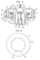
- the rotatable head 4 comprises, as shown in a vertical sectional view of Fig. 2, a cylindrical upper case 7 which is securely attached to the output shaft 5 from the gear housing 3 by means of nuts 6 and a lower case 8 releasably attached to the upper case by engaging recess 7a with a projection 8a formed opposite to each other at their peripheral surfaces.
- said head 4 is rotated by the prime mover 2 in a predetermined direction.
- Said upper case 7 has a top wall and a peripheral wall whereas said lower case 8 has a bottom portion and a peripheral wall.
- Said reel 9 has a bore in a center thereof into which the output shaft 5 is inserted to allow a rotation of the reel 9 thereabout and a slidable movement of the same in an axial direction.
- a depressing member 10 projecting outwardly from a guide opening 8b formed in the center of the bottom portion of the lower case 8 is formed integral with the lower portion of the reel 9.
- the reel 9 has an upper flange 9b .and a lower flange 9c formed integral therewith.
- Two lines of cord 13 of synthetic resin are wound in the reverse direction to the rotating direction of the rotatable head between the upper flange 9b and the lower flange 9c . Each free end of the lines is extended outwardly from each of two guide apertures formed in the peripheral wall of the upper case 7.
- a coil spring 14 is interposed between the inner surface of the top wall of the upper case 7 and the depressing member 10 integral with the reel 9.
- the lower flange 9c of the reel 9 is urged to the inner bottom surface of the lower case 8 and the depressing member 10 is caused to project outwardly through the guide opening 8b of the lower case 8.
- Annular ratchet mechanisms 1 5 , 16 formed in the inner surface of the upper case 7 and the upper reel flange are arranged in facing relation to each other around the coil spring 14.
- Annular engaging mechanisms 17 and 18 for engaging and disengaging the reel with and from the head 4 are formed in facing relation to each other in the inner bottom surface of the lower case 8 and the lower outer surface of the lower flange 9c.
- Said tip 20 3 is formed at the rearwardmost end of said slant surface 20 2 .
- the respective engaging mechanisms 17 and 18 comprise eight recesses 21 and eight projections 22 both arranged in a circle with equal angular specings and sized to permit engagement with other.
- Each recess 21 has a vertical rearward surface 21a, a slant forward surface 2lb and flat surface 21c therebetween whereas each projection 22 has a vertical rearward surface 22a, a slant forward surface 22b and a flat surface 22c therebetween.
- Fig. 3a shows the state that the ratchet teeth 20 of the reel are released from the ratchet teeth 19 of the upper case 7 and the projections 22 of the reel 9 are engaged with the recesses 21 of the lower case 8 due to the biasing of the coil spring 14.
- the rotatable head 4 is rotated in the arrowed direction in the state in which the projections 22 are in mesh with the recesses 21 so that the reel 9 is rotated together with the rotatable head 4 in the same direction.
- centrifugal force works on the cord 13 to make the same radially extend through the guide aperture 7b for effecting the cutting operation.
- the wound cord 13 will not loosen even if the portion extending outside is subjected to centrifugal force since the cord 13 is wound around the reel 9 in the reverse direction to the rotating direction of the rotatable head.
- ratchet teeth 19 and 20 and the recesses 21 and projections 22 are formed as follows:
- the reel 9 performs a stepwise rotation rearward or in a direction to loosen the winding of the cord 13 before being stopped. Accordingly, the wound cord 13 is loosened by one increment.
- the reel 9 descends relative to the head 4 in an arrowed direction by biasing of the coil spring 14, as shown in Fig. 3d.
- the projections 22 are engaged with the recesses 21 by sliding down the slant surfaces to return to the state as shwon in Fig. 3a.
- the loosened length of the cord 13 (corresponding to the length of said one increment by the ratchet teeth 19, 20) is automatically drawn through the guide aperture 7 b of the rotatable head 4 by the centrifugal force upon the head rotation.
- the number of the ratchet teeth and the recesses and projections is eight, respectively, the number-may be varied depending on the length of the extended cord.
- the vertical sides of the ratchet teeth 19 and the recesses 21 are formed in the same phase while the slant surfaces of the ratchet teeth 20 in part extend such that the vertical surfaces of the ratchet teeth 20 are out of phase rearwardly with respect to the head rotation by an interval d from the vertical sides of the ratchet teeth 19 during the engagement of the recesses 21 and the projections 22.
- FIG. 1 A second embodiment of the invention will be described in conjunction with the drawings including Fig. 4 through Fig. 7d.
- the general structure of the second embodiment is substantially the same as that of the first embodiment as shown in Fig. 1.
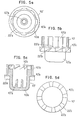
- the depressing member 10' having a U-shaped cross section is cylindrical.
- an annular guide wall 10'b is formed in which a guide shaft 23' threadedly attached to the boss member 5'a of the output shaft 5' is inserted.
- a coil spring 14' is interposed between the bottom wall 10'a of the depressing member 10' and the inner wall of the upper case 7' along the peripheral surface of the guide wall 10'b. A downward biasing of the coil spring 14' allows the depressing member 10' to project outwardly from the lower case 8' through a an opening-8'b formed in the center bottom portion of the lower case 8'.
- Each ratchet tooth 10'c includes a vertical surface 10'c, a slant surface 10'c2 and a tip 10'c3.
- each ratchet tooth 7'd is annularly formed, each ratchet tooth 7'd including a vertical surface 7'd. a slant surface 7'd2 and a tip 7'd3. Said slant surface 7'd2 serves as a guide surface for each ratchet tooth 10'c by permitting a stepwise rotation of the depressing member 10' rearwardly with respect to the head rotation.
- eight recesses 21' with a vertical surface 21'a and a slant wall 21'b are formed to cooperate with the projections 22' formed in the lower surface of the brim 10'e of the depressing member 10'.
- Each recess 21' has a flat surface 21'c between said vertical surface 21'a and a slant surface 21'b.
- the reel 9' has a body 9'a, an upper flange 9'b, a lower flange 9'c and an intermediate partition 9'd.
- Two lengths of the synthetic resin cord 13' are folded in half and the folded portion of the cord is secured to the intermediate partition 9'd and each end of the folded cord is wound around the body 9'a divided into upper and lower parts by the partition.
- Each one end of the cord 13" is extended outwardly through an eyelet 24', which is provided with a gap and nested into a slit formed in the peripheral wall of the lower case 8'.
- a plurality of vertical recesses 9'e are formed in the inner periphery of the body 9'a of the reel 9' with equal angular spacings therebetween.
- Each recess 9'e is engaged with each projection 10'd formed in the peripheral wall of the depressing member 10', so that the reel 9' may be releasably fitted into the depressing member 10' in dovetail fashion to rotate together in the same direction.
- the lower flange 9'c of the reel 9 abuts against the brim 10'e of the depressing member 10.
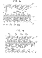
- Fig. 7a shows the state in which the depressing member 10' is biased downwardly by the coil spring to maintain ratchet teeth 10'c of the depressing member 10' out of engagement with the ratchet 7'd of the upper case 7' while the projections 22' of the depressing member 10' are in engagement with the recesses 21' of the lower case 8' such that the slant surface 22'b of each projection 22' is in contact with the slant surface 21'b of each recess 21'.
- the slant surfaces 7'd2 of the ratchet teeth 7'd are formed to face in a direction reverse to the head rotation while the slant surfaces 10'c2 of the ratchet teeth 10'c face said slant surfaces 7'd2. With this positional relationship, said slant surfaces serve as guide surfaces for the ratchet teeth 10'c when the ratchet teeth 7'd and 10'c come into engagement with each other.
- the tip 10'c3 of each ratchet tooth 10'c is positioned rearwardly out of phase with the tip 7'd3 of each ratchet tooth 7'd by a predetermined distance d with respect to the head rotation at least when the vertical surface 21'a of each recess 21' is advanced to contact the vertical surface 22'a of each projection 22'.
- Figs. 5b through 5d show the change in the positional relationship of the elements mentioned above at the time of the paying out operation of the cord 13'.
- the depressing member 10' rises relative to the head 4' composed of the upper case 7' and the lower case 8' in an arrowed direction shown in Fig. 5b.
- the projections 22' of the depressing member 10' are released from the recesses 21' of the lower case 8' and the ratchet teeth 10'c come into contact with the ratchet teeth 7'd of the upper case 7'.
- the reference numeral 1 to 5 referred to the respective ratchet teeth are intended for clarification of the chanc; in the relationship of engagement.
- each ratchet tooth 10'c When the depressing member 10' is further pushed against the ground, the tip 10'c3 of each ratchet tooth 10'c is caused to slide along the slant surface 7'd2 in a rearward direction until said ratchet teeth 7'd and 10'c come into full engagement as shown in Fig. 5c. That is, the depressing member 10' performs a rearward stepwise rotation in the arrowed direction in Fig. 5c. Therefore, the reel 9' is also rotated in the same direction to loosen the wound cord 13'by an amount corresponding to the rearward - stepwise rotation of the reel 9'.
- the head 4' including the upper case 7' and the lower case 8' is raised by biasing of the coil spring 14' and the slant surfaces 22'b of the projections 22' come into contact with the slant surfaces 21'b of the recesses 21' leaving part of the slant surfaces 21'b uncontacted by the distance of D which is larger than the distance d. Then the projections 22' slide down the slant surfaces 21'b to the left by the interval D and stop to return to the state as shown in Fig. 7a.
- the rotatable head 4' is rotated again, the loosened length of the cord 13' is automatically extended from the eyelet 24' by centrifugal force upon rotation of the reel 4'.
- the cord 13' is easily extended without getting entangled since as described above each of two lines of the cord 13' is wound around the body 9'a divided by the intermediate partition 9'd of the reel 9'.
- the number of the ratchet teeth is eight, respectively, the number may be increased depending on the length of the extended cord.
- each recesses 21" and projections 22" are of rectangular configuration, said recesses 21" being larger than said projections 22" in their circumferential sizes. Since each recess and each projection have respective vertical rearward wall surfaces 21"a and 22"a whereas each ratchet tooth 19" and 20" have respective vertical-rearward wall surfaces 19" 1 and 20" 1 .
- the vertical surface 19"1 of each ratchet tooth and the vertical rearward surface 2 2"a of each projection 22" are formed in the same phase with each other whereas the vertical surface 20" of each ratchet tooth 20 is formed rearwardly out of phase with the vertical forward wall surface 22"b of each projection 22".
- the tip 20" 3 are positioned rearwardly out of phase from the tip 19" 3 by the distance d when the rearward vertical surface 21"a and the rearward vertical wall surfaces 22"a are brought into contact with each other as shown in Fig. 8b.
- FIG. 9a through Fig. 11 A still further embodiment of the invention will be described in conjunction with Fig. 9a through Fig. 11.
- the general structure of this embodiment is substantially the same as that the embodiment shown in Figs. 1 through 3d except for the following points. That is, as shown in Figs. 9a and 9b, a reel 9"' of synthetic resin has an upper flange 9"'b and a lower flange 9"'c and is molded into generally H-shaped into cross section.
- 9"'a designates the body of the reel 9"'; 9"'f, an annular groove nested with one end of the coil spring for biasing the reel 9"'; and 10"', a depressing member.
- two slits 25"' are formed at portions diametrically opposite to each other, each being a little smaller than the diameter of the cord 13"'. As described above, the whole length of the cord is folded in half. The folded portion of the cord 13"' is secured to the body 9"'a of the reel 9"'. Two lines of the cord 13"' in parallel are wound in the same direction.
- each end of the two lines of the cord 13"' is forcibly drawn into each slits 25"' formed in the upper flange 9"'b, each end of the cord 13"' is retained in said slit 25"' to prevent the wound cord 13"' from loosening since the width of the slit 25"' is formed a little smaller than the diameter of the cord 13"', as described above.
- Figs. 10a through 10c show an eyelet 24"'.
- the eyelet 24"' defining an outlet 26"' is generally U-shaped having a gap 27" at an upper portion thereof.- Said gap 27"' continues to the outlet 26" ', which serves as a guide aperture for the cord.
- the eyelet 24"' is further formed with recesses 24"'a and 24"'b in both side walls and under wall thereof. By using these recesses, the eyelet is pressed into a cutout formed in the peripheral surface 8"'b of a lower case 8"' and opening upwardly.
- each end of the cord 13" ' retained within the slit 25" is positioned so as to be ready for being drawn fit into the eyelet 24"'. Then, as described in Fig.11, each end of the cord is drawn out from the slit 25"' and lowered downwardly to be guided into the outlet 26"' through the gap 27"' of the eyelet 24"'.
- each end of the cord 13"' wound around the reel 9"' may be extended from the eyelet 24"' very easily.
- the lower case 8 is covered with the upper case 7 and the catch 8a of the lower case 8 is engaged with a catch hole 7a of the upper case 7.
- This structural relationship is entirely the same as the embodiment of Figs. 9a through 11.
- the gap 27"' of the eyelet 24"' is blocked by the lower portion of the periphery wall of the upper case 7.
- This embodiment has the following effects; the cord is free from loosening while the assembly of the reel and the rotatable head is very easy since the end of the cord is temporarily retained in the reel, and the gap formed in the eyelet and continuous to the outlet therein makes it easy to draw the cord temporarily retained in the slit of the reel flange out into the eyelet for paying out the cord therethrough.
- the present invention has the following effects.
Landscapes
- Life Sciences & Earth Sciences (AREA)
- Environmental Sciences (AREA)
- Harvester Elements (AREA)
Applications Claiming Priority (6)
| Application Number | Priority Date | Filing Date | Title |
|---|---|---|---|
| JP110248/85 | 1985-05-24 | ||
| JP60110248A JPS61268106A (ja) | 1985-05-24 | 1985-05-24 | 刈払機のコ−ド繰出し装置 |
| JP61048624A JPS62208213A (ja) | 1986-03-07 | 1986-03-07 | 刈払機のコ−ド繰出し装置 |
| JP48624/85 | 1986-03-07 | ||
| JP51494/85 | 1986-03-11 | ||
| JP61051494A JPS62210911A (ja) | 1986-03-11 | 1986-03-11 | 刈払機 |
Publications (3)
| Publication Number | Publication Date |
|---|---|
| EP0203011A2 true EP0203011A2 (fr) | 1986-11-26 |
| EP0203011A3 EP0203011A3 (en) | 1988-01-07 |
| EP0203011B1 EP0203011B1 (fr) | 1991-09-25 |
Family
ID=27293356
Family Applications (1)
| Application Number | Title | Priority Date | Filing Date |
|---|---|---|---|
| EP86401092A Expired - Lifetime EP0203011B1 (fr) | 1985-05-24 | 1986-05-23 | Appareil pour couper l'herbe |
Country Status (3)
| Country | Link |
|---|---|
| US (1) | US4672798A (fr) |
| EP (1) | EP0203011B1 (fr) |
| AU (1) | AU578004B2 (fr) |
Cited By (6)
| Publication number | Priority date | Publication date | Assignee | Title |
|---|---|---|---|---|
| EP0271762A1 (fr) * | 1986-12-17 | 1988-06-22 | White Consolidated Industries, Inc. | Mécanisme d'alimentation en filament pour tondeuse à fil de coupe |
| EP0525195A1 (fr) * | 1991-01-14 | 1993-02-03 | KANOU, Takahiro | Organe de coupe rotatif pour tondeuse a gazon |
| EP0315603B1 (fr) * | 1987-11-04 | 1993-12-29 | Maria Rosa Calcinai | Appareil de coupe à filament |
| EP0784919A1 (fr) * | 1995-12-18 | 1997-07-23 | ACTIVE srl | Tête de coupe en particulier pour tondeuse à filament |
| WO2001049101A1 (fr) * | 2000-01-04 | 2001-07-12 | Arnetoli Motor Di Arnetoli Fabrizio | Bobine d'enroulement d'une corde coupante destinee a un dispositif de tonte de gazon et tete de dispositif de tonte de gazon integrant ladite bobine |
| EP2294908A1 (fr) * | 2008-03-05 | 2011-03-16 | Starting Industrial Co., Ltd. | Mécanisme de coupe rotatif pour tondeuse |
Families Citing this family (33)
| Publication number | Priority date | Publication date | Assignee | Title |
|---|---|---|---|---|
| US4860451A (en) * | 1986-11-28 | 1989-08-29 | Allegretti & Company | String trimmer |
| US4823465A (en) * | 1986-12-17 | 1989-04-25 | White Consolidated Industries, Inc. | Line feed mechanism for line trimmers |
| US4779405A (en) * | 1987-05-01 | 1988-10-25 | Piston Powered Products, Inc. | Line-feeding head for a rotary line trimmer |
| JPH0620351Y2 (ja) * | 1987-06-11 | 1994-06-01 | 株式会社共立 | 可撓性フイラメント式草刈機のヘツド構造 |
| AU592679B2 (en) * | 1987-10-28 | 1990-01-18 | White Consolidated Industries, Inc. | Apparatus for cutting vegetation |
| US4942664A (en) * | 1988-05-26 | 1990-07-24 | Allegretti & Company | String trimmer with automatic feed |
| US4959904A (en) * | 1989-02-02 | 1990-10-02 | Proulx Raymond E | Simple flail feedout mechanism for a rotary mower |
| US5020223A (en) * | 1989-11-02 | 1991-06-04 | White Consolidated Industries, Inc. | Simplified bump-feed type cutting head assembly for flexible line trimmers |
| US5311665A (en) * | 1990-11-16 | 1994-05-17 | Diatop Corporation | Cutting head for a cord type mower |
| JP3113270B2 (ja) * | 1990-11-16 | 2000-11-27 | 杉原林機株式会社 | コード型草刈機の刈刃装置におけるコード繰出し機構 |
| AU633241B3 (en) * | 1992-04-24 | 1993-01-21 | Chef'n Corporation | Method and apparatus for peeling produce such as garlic |
| IL102887A (en) * | 1992-08-20 | 1994-10-21 | Shimon Ner Gaon | Release mechanism for rotating head for pruning machines |
| US5657542A (en) * | 1993-12-22 | 1997-08-19 | The Toro Company | Filament trimmer head |
| US5881465A (en) * | 1994-04-08 | 1999-03-16 | Wci Outdoor Products, Inc. | Line head for flexible line trimmer |
| AU1499495A (en) * | 1994-04-08 | 1995-10-19 | Wci Outdoor Products, Inc. | Line head for flexible line trimmer |
| WO2005110685A2 (fr) * | 2004-05-11 | 2005-11-24 | Alliss George E | Coupe-herbe |
| US8025249B2 (en) * | 2007-11-16 | 2011-09-27 | Alliss George E | Bi-directional trimmer head spool with curved trimmer line guide |
| US20090172955A1 (en) * | 2008-01-03 | 2009-07-09 | Morris John F | String trimmer head |
| US8910387B2 (en) * | 2008-04-22 | 2014-12-16 | George Everett Alliss | String trimmer head configuration and method |
| US9516807B2 (en) | 2008-04-22 | 2016-12-13 | George E. Alliss | Straight through line feed vegetation trimmer apparatus |
| US9924631B2 (en) | 2008-04-22 | 2018-03-27 | George E. Alliss | Spool for straight through line feed vegetation trimmer apparatus with modules and spokes |
| US8745879B2 (en) * | 2008-04-22 | 2014-06-10 | George E. Alliss | String trimmer head configuration and method |
| EP2319288B1 (fr) * | 2009-01-22 | 2012-02-29 | Techtronic Outdoor Products Technology Limited | Tête à fil pour tondeuse |
| JP5419219B2 (ja) * | 2009-12-25 | 2014-02-19 | スターテング工業株式会社 | 刈払い機用ロータリカッタ |
| US20110239468A1 (en) * | 2010-03-31 | 2011-10-06 | Paul Conlon | Trimmer head having a hinged housing for use in flexible line rotary trimmers systems |
| JP5271433B2 (ja) * | 2011-04-15 | 2013-08-21 | ブイアイブイエンジニアリング株式会社 | 刈払機 |
| JP2013034403A (ja) * | 2011-08-04 | 2013-02-21 | Makita Corp | 刈払機 |
| JP5959290B2 (ja) * | 2012-04-25 | 2016-08-02 | スターテング工業株式会社 | 刈払い機用ロータリカッタ |
| ES2772766T3 (es) | 2014-10-21 | 2020-07-08 | Tecomec Srl | Un cuerpo de golpeteo para un cabezal para una recortadora de bordes y un cabezal para una recortadora de bordes |
| USD970321S1 (en) | 2014-11-20 | 2022-11-22 | Torvent Llc | Line trimmer component |
| US11229160B2 (en) * | 2015-06-22 | 2022-01-25 | Shakespeare Company, Llc | Easy to load trimmer head with forced discharge |
| US11122735B2 (en) | 2017-09-12 | 2021-09-21 | Milwaukee Electric Tool Corporation | String trimmer head and spool |
| US11903339B1 (en) * | 2022-10-10 | 2024-02-20 | Imack Laydera-Collins | Externally windable trimmer head |
Citations (2)
| Publication number | Priority date | Publication date | Assignee | Title |
|---|---|---|---|---|
| JPS5417651B2 (fr) | 1977-02-21 | 1979-07-02 | ||
| GB2078075A (en) | 1980-06-14 | 1982-01-06 | Komatsu Zenoa Kk | A mowing machine |
Family Cites Families (8)
| Publication number | Priority date | Publication date | Assignee | Title |
|---|---|---|---|---|
| US4209902A (en) * | 1977-12-19 | 1980-07-01 | Emerson Electric Co. | Apparatus for cutting vegetation |
| US4274201A (en) * | 1978-02-13 | 1981-06-23 | Berkley And Company, Inc. | Rotary cutting assembly with filament feed |
| US4183138A (en) * | 1978-03-08 | 1980-01-15 | Weed Eater, Inc. | Apparatus for cutting vegetation |
| US4203212A (en) * | 1978-07-13 | 1980-05-20 | Proulx Raymond E | Flail feedout mechanism for a rotary mower |
| DE3005968C2 (de) * | 1980-02-16 | 1990-08-23 | Gardena Kress + Kastner Gmbh, 7900 Ulm | Fadenschneider |
| US4281505A (en) * | 1980-06-09 | 1981-08-04 | Outboard Marine Corporation | Filament mower with filament advancing mechanism |
| US4419822A (en) * | 1981-01-14 | 1983-12-13 | Black & Decker Inc. | Bump-feed trimmer |
| JPS6083508A (ja) * | 1983-10-15 | 1985-05-11 | タナカ工業株式会社 | ナイロンコ−ド型刈払機 |
-
1986
- 1986-05-23 US US06/866,503 patent/US4672798A/en not_active Expired - Lifetime
- 1986-05-23 AU AU57870/86A patent/AU578004B2/en not_active Ceased
- 1986-05-23 EP EP86401092A patent/EP0203011B1/fr not_active Expired - Lifetime
Patent Citations (2)
| Publication number | Priority date | Publication date | Assignee | Title |
|---|---|---|---|---|
| JPS5417651B2 (fr) | 1977-02-21 | 1979-07-02 | ||
| GB2078075A (en) | 1980-06-14 | 1982-01-06 | Komatsu Zenoa Kk | A mowing machine |
Cited By (11)
| Publication number | Priority date | Publication date | Assignee | Title |
|---|---|---|---|---|
| EP0271762A1 (fr) * | 1986-12-17 | 1988-06-22 | White Consolidated Industries, Inc. | Mécanisme d'alimentation en filament pour tondeuse à fil de coupe |
| EP0315603B1 (fr) * | 1987-11-04 | 1993-12-29 | Maria Rosa Calcinai | Appareil de coupe à filament |
| EP0525195A1 (fr) * | 1991-01-14 | 1993-02-03 | KANOU, Takahiro | Organe de coupe rotatif pour tondeuse a gazon |
| EP0525195A4 (en) * | 1991-01-14 | 1993-06-30 | Takahiro Kanou | Rotary cutter for mowing machine |
| US5345683A (en) * | 1991-01-14 | 1994-09-13 | Takahiro Kanou | Rotary cutter for mowing machine |
| EP0784919A1 (fr) * | 1995-12-18 | 1997-07-23 | ACTIVE srl | Tête de coupe en particulier pour tondeuse à filament |
| US5765287A (en) * | 1995-12-18 | 1998-06-16 | Active S.R.L. | Cutting head for nylon-cord type mowers |
| WO2001049101A1 (fr) * | 2000-01-04 | 2001-07-12 | Arnetoli Motor Di Arnetoli Fabrizio | Bobine d'enroulement d'une corde coupante destinee a un dispositif de tonte de gazon et tete de dispositif de tonte de gazon integrant ladite bobine |
| US6851191B2 (en) | 2000-01-04 | 2005-02-08 | Arnetoli Motor Di Arnetoli Fabrizio | Reel for winding a cutting cord for a grass-cutting device and head for grass-cutting device incorporating said reel |
| EP2294908A1 (fr) * | 2008-03-05 | 2011-03-16 | Starting Industrial Co., Ltd. | Mécanisme de coupe rotatif pour tondeuse |
| EP2294908A4 (fr) * | 2008-03-05 | 2012-10-10 | Starting Ind | Mécanisme de coupe rotatif pour tondeuse |
Also Published As
| Publication number | Publication date |
|---|---|
| US4672798A (en) | 1987-06-16 |
| EP0203011A3 (en) | 1988-01-07 |
| AU5787086A (en) | 1986-11-27 |
| EP0203011B1 (fr) | 1991-09-25 |
| AU578004B2 (en) | 1988-10-06 |
Similar Documents
| Publication | Publication Date | Title |
|---|---|---|
| EP0203011A2 (fr) | Appareil pour couper l'herbe | |
| CA2887750C (fr) | Tete de decoupe | |
| EP0426039B1 (fr) | Dispositif de tête de coupage à poussoir simplifié pour trimmer le gazon avec de la fibre flexible | |
| CA2464857C (fr) | Tete de fil fixee pour appareils de coupe rotatifs a fil flexible | |
| US5765287A (en) | Cutting head for nylon-cord type mowers | |
| US4349962A (en) | Cutting down machine | |
| US4236309A (en) | Flexible line trimmer with line feeding apparatus | |
| EP0676127B1 (fr) | Tête de coupe pour dispositif de coupe fil flexible | |
| US10537057B2 (en) | Spool assembly for a trimmer head | |
| CN110809989B (zh) | 打草头 | |
| JPH0135627Y2 (fr) | ||
| JPH0141282B2 (fr) | ||
| JP2007312769A (ja) | 刈払い機用ロータリカッタ | |
| EP3205200A1 (fr) | Tête faucheuse avec cassette de fil | |
| US4738085A (en) | Rotary cutter for mowers | |
| AU2022201494A1 (en) | Trimmer head | |
| EP0271762B1 (fr) | Mécanisme d'alimentation en filament pour tondeuse à fil de coupe | |
| CN112088644B (zh) | 打草机及其打草头 | |
| EP1004232B1 (fr) | Outil de coupe rotatif pour faucheuse | |
| JPH0369248B2 (fr) | ||
| JPS63216406A (ja) | 刈払機のコ−ド繰出し装置 | |
| CN219165146U (zh) | 一种自动收放线的打草头及园林工具 | |
| JPH0451126B2 (fr) | ||
| JPS62210911A (ja) | 刈払機 | |
| CN219330065U (zh) | 自动收放线的打草头及园林工具 |
Legal Events
| Date | Code | Title | Description |
|---|---|---|---|
| PUAI | Public reference made under article 153(3) epc to a published international application that has entered the european phase |
Free format text: ORIGINAL CODE: 0009012 |
|
| AK | Designated contracting states |
Kind code of ref document: A2 Designated state(s): AT BE CH DE FR GB IT LI LU NL SE |
|
| PUAL | Search report despatched |
Free format text: ORIGINAL CODE: 0009013 |
|
| AK | Designated contracting states |
Kind code of ref document: A3 Designated state(s): AT BE CH DE FR GB IT LI LU NL SE |
|
| 17P | Request for examination filed |
Effective date: 19880507 |
|
| 17Q | First examination report despatched |
Effective date: 19900514 |
|
| RBV | Designated contracting states (corrected) |
Designated state(s): FR GB IT |
|
| GRAA | (expected) grant |
Free format text: ORIGINAL CODE: 0009210 |
|
| REG | Reference to a national code |
Ref country code: DE Ref legal event code: 8566 |
|
| AK | Designated contracting states |
Kind code of ref document: B1 Designated state(s): FR GB IT |
|
| ET | Fr: translation filed | ||
| ITF | It: translation for a ep patent filed |
Owner name: DR. ING. A. RACHELI & C. |
|
| PLBE | No opposition filed within time limit |
Free format text: ORIGINAL CODE: 0009261 |
|
| STAA | Information on the status of an ep patent application or granted ep patent |
Free format text: STATUS: NO OPPOSITION FILED WITHIN TIME LIMIT |
|
| 26N | No opposition filed | ||
| PGFP | Annual fee paid to national office [announced via postgrant information from national office to epo] |
Ref country code: FR Payment date: 19950322 Year of fee payment: 10 |
|
| PGFP | Annual fee paid to national office [announced via postgrant information from national office to epo] |
Ref country code: GB Payment date: 19950516 Year of fee payment: 10 |
|
| PG25 | Lapsed in a contracting state [announced via postgrant information from national office to epo] |
Ref country code: GB Effective date: 19960523 |
|
| GBPC | Gb: european patent ceased through non-payment of renewal fee |
Effective date: 19960523 |
|
| PG25 | Lapsed in a contracting state [announced via postgrant information from national office to epo] |
Ref country code: FR Effective date: 19970131 |
|
| REG | Reference to a national code |
Ref country code: FR Ref legal event code: ST |
|
| PG25 | Lapsed in a contracting state [announced via postgrant information from national office to epo] |
Ref country code: IT Free format text: LAPSE BECAUSE OF NON-PAYMENT OF DUE FEES Effective date: 20050523 |