EP0202777B1 - Scheibenschneidmaschine für Lebensmittel mit rotierendem Messer - Google Patents
Scheibenschneidmaschine für Lebensmittel mit rotierendem Messer Download PDFInfo
- Publication number
- EP0202777B1 EP0202777B1 EP86302956A EP86302956A EP0202777B1 EP 0202777 B1 EP0202777 B1 EP 0202777B1 EP 86302956 A EP86302956 A EP 86302956A EP 86302956 A EP86302956 A EP 86302956A EP 0202777 B1 EP0202777 B1 EP 0202777B1
- Authority
- EP
- European Patent Office
- Prior art keywords
- blade
- magazine
- product
- slicer
- support
- Prior art date
- Legal status (The legal status is an assumption and is not a legal conclusion. Google has not performed a legal analysis and makes no representation as to the accuracy of the status listed.)
- Expired - Lifetime
Links
- 230000005540 biological transmission Effects 0.000 claims description 5
- 230000007246 mechanism Effects 0.000 claims description 5
- 239000002245 particle Substances 0.000 claims description 5
- 230000002093 peripheral effect Effects 0.000 claims description 4
- 230000002401 inhibitory effect Effects 0.000 claims description 2
- 230000013011 mating Effects 0.000 claims 1
- 230000000452 restraining effect Effects 0.000 claims 1
- 238000000926 separation method Methods 0.000 claims 1
- 230000001681 protective effect Effects 0.000 abstract description 2
- 230000036961 partial effect Effects 0.000 description 7
- 230000006835 compression Effects 0.000 description 3
- 238000007906 compression Methods 0.000 description 3
- 238000010276 construction Methods 0.000 description 3
- 230000008901 benefit Effects 0.000 description 2
- 230000008859 change Effects 0.000 description 2
- 235000013305 food Nutrition 0.000 description 2
- 238000009434 installation Methods 0.000 description 2
- 235000013372 meat Nutrition 0.000 description 2
- 230000004075 alteration Effects 0.000 description 1
- 238000004140 cleaning Methods 0.000 description 1
- 238000001514 detection method Methods 0.000 description 1
- 239000002184 metal Substances 0.000 description 1
- 230000004048 modification Effects 0.000 description 1
- 238000012986 modification Methods 0.000 description 1
- 229920003023 plastic Polymers 0.000 description 1
- 230000009467 reduction Effects 0.000 description 1
- 230000000284 resting effect Effects 0.000 description 1
- 230000000717 retained effect Effects 0.000 description 1
Images


Classifications
-
- B—PERFORMING OPERATIONS; TRANSPORTING
- B26—HAND CUTTING TOOLS; CUTTING; SEVERING
- B26D—CUTTING; DETAILS COMMON TO MACHINES FOR PERFORATING, PUNCHING, CUTTING-OUT, STAMPING-OUT OR SEVERING
- B26D7/00—Details of apparatus for cutting, cutting-out, stamping-out, punching, perforating, or severing by means other than cutting
- B26D7/06—Arrangements for feeding or delivering work of other than sheet, web, or filamentary form
-
- B—PERFORMING OPERATIONS; TRANSPORTING
- B26—HAND CUTTING TOOLS; CUTTING; SEVERING
- B26D—CUTTING; DETAILS COMMON TO MACHINES FOR PERFORATING, PUNCHING, CUTTING-OUT, STAMPING-OUT OR SEVERING
- B26D1/00—Cutting through work characterised by the nature or movement of the cutting member or particular materials not otherwise provided for; Apparatus or machines therefor; Cutting members therefor
- B26D1/01—Cutting through work characterised by the nature or movement of the cutting member or particular materials not otherwise provided for; Apparatus or machines therefor; Cutting members therefor involving a cutting member which does not travel with the work
- B26D1/12—Cutting through work characterised by the nature or movement of the cutting member or particular materials not otherwise provided for; Apparatus or machines therefor; Cutting members therefor involving a cutting member which does not travel with the work having a cutting member moving about an axis
- B26D1/14—Cutting through work characterised by the nature or movement of the cutting member or particular materials not otherwise provided for; Apparatus or machines therefor; Cutting members therefor involving a cutting member which does not travel with the work having a cutting member moving about an axis with a circular cutting member, e.g. disc cutter
- B26D1/157—Cutting through work characterised by the nature or movement of the cutting member or particular materials not otherwise provided for; Apparatus or machines therefor; Cutting members therefor involving a cutting member which does not travel with the work having a cutting member moving about an axis with a circular cutting member, e.g. disc cutter rotating about a movable axis
- B26D1/16—Cutting through work characterised by the nature or movement of the cutting member or particular materials not otherwise provided for; Apparatus or machines therefor; Cutting members therefor involving a cutting member which does not travel with the work having a cutting member moving about an axis with a circular cutting member, e.g. disc cutter rotating about a movable axis mounted on a movable arm or the like
-
- B—PERFORMING OPERATIONS; TRANSPORTING
- B26—HAND CUTTING TOOLS; CUTTING; SEVERING
- B26D—CUTTING; DETAILS COMMON TO MACHINES FOR PERFORATING, PUNCHING, CUTTING-OUT, STAMPING-OUT OR SEVERING
- B26D7/00—Details of apparatus for cutting, cutting-out, stamping-out, punching, perforating, or severing by means other than cutting
- B26D7/08—Means for treating work or cutting member to facilitate cutting
- B26D7/12—Means for treating work or cutting member to facilitate cutting by sharpening the cutting member
-
- B—PERFORMING OPERATIONS; TRANSPORTING
- B26—HAND CUTTING TOOLS; CUTTING; SEVERING
- B26D—CUTTING; DETAILS COMMON TO MACHINES FOR PERFORATING, PUNCHING, CUTTING-OUT, STAMPING-OUT OR SEVERING
- B26D7/00—Details of apparatus for cutting, cutting-out, stamping-out, punching, perforating, or severing by means other than cutting
- B26D7/22—Safety devices specially adapted for cutting machines
- B26D7/24—Safety devices specially adapted for cutting machines arranged to disable the operating means for the cutting member
-
- Y—GENERAL TAGGING OF NEW TECHNOLOGICAL DEVELOPMENTS; GENERAL TAGGING OF CROSS-SECTIONAL TECHNOLOGIES SPANNING OVER SEVERAL SECTIONS OF THE IPC; TECHNICAL SUBJECTS COVERED BY FORMER USPC CROSS-REFERENCE ART COLLECTIONS [XRACs] AND DIGESTS
- Y10—TECHNICAL SUBJECTS COVERED BY FORMER USPC
- Y10T—TECHNICAL SUBJECTS COVERED BY FORMER US CLASSIFICATION
- Y10T83/00—Cutting
- Y10T83/081—With randomly actuated stopping means
- Y10T83/099—Manually operated
-
- Y—GENERAL TAGGING OF NEW TECHNOLOGICAL DEVELOPMENTS; GENERAL TAGGING OF CROSS-SECTIONAL TECHNOLOGIES SPANNING OVER SEVERAL SECTIONS OF THE IPC; TECHNICAL SUBJECTS COVERED BY FORMER USPC CROSS-REFERENCE ART COLLECTIONS [XRACs] AND DIGESTS
- Y10—TECHNICAL SUBJECTS COVERED BY FORMER USPC
- Y10T—TECHNICAL SUBJECTS COVERED BY FORMER US CLASSIFICATION
- Y10T83/00—Cutting
- Y10T83/202—With product handling means
- Y10T83/2092—Means to move, guide, or permit free fall or flight of product
- Y10T83/2192—Endless conveyor
-
- Y—GENERAL TAGGING OF NEW TECHNOLOGICAL DEVELOPMENTS; GENERAL TAGGING OF CROSS-SECTIONAL TECHNOLOGIES SPANNING OVER SEVERAL SECTIONS OF THE IPC; TECHNICAL SUBJECTS COVERED BY FORMER USPC CROSS-REFERENCE ART COLLECTIONS [XRACs] AND DIGESTS
- Y10—TECHNICAL SUBJECTS COVERED BY FORMER USPC
- Y10T—TECHNICAL SUBJECTS COVERED BY FORMER US CLASSIFICATION
- Y10T83/00—Cutting
- Y10T83/303—With tool sharpener or smoother
-
- Y—GENERAL TAGGING OF NEW TECHNOLOGICAL DEVELOPMENTS; GENERAL TAGGING OF CROSS-SECTIONAL TECHNOLOGIES SPANNING OVER SEVERAL SECTIONS OF THE IPC; TECHNICAL SUBJECTS COVERED BY FORMER USPC CROSS-REFERENCE ART COLLECTIONS [XRACs] AND DIGESTS
- Y10—TECHNICAL SUBJECTS COVERED BY FORMER USPC
- Y10T—TECHNICAL SUBJECTS COVERED BY FORMER US CLASSIFICATION
- Y10T83/00—Cutting
- Y10T83/485—Cutter with timed stroke relative to moving work
- Y10T83/494—Uniform periodic tool actuation
-
- Y—GENERAL TAGGING OF NEW TECHNOLOGICAL DEVELOPMENTS; GENERAL TAGGING OF CROSS-SECTIONAL TECHNOLOGIES SPANNING OVER SEVERAL SECTIONS OF THE IPC; TECHNICAL SUBJECTS COVERED BY FORMER USPC CROSS-REFERENCE ART COLLECTIONS [XRACs] AND DIGESTS
- Y10—TECHNICAL SUBJECTS COVERED BY FORMER USPC
- Y10T—TECHNICAL SUBJECTS COVERED BY FORMER US CLASSIFICATION
- Y10T83/00—Cutting
- Y10T83/566—Interrelated tool actuating means and means to actuate work immobilizer
- Y10T83/5815—Work-stop abutment
- Y10T83/5842—Stop partakes of tool motion
- Y10T83/5851—Carried by tool or tool support
-
- Y—GENERAL TAGGING OF NEW TECHNOLOGICAL DEVELOPMENTS; GENERAL TAGGING OF CROSS-SECTIONAL TECHNOLOGIES SPANNING OVER SEVERAL SECTIONS OF THE IPC; TECHNICAL SUBJECTS COVERED BY FORMER USPC CROSS-REFERENCE ART COLLECTIONS [XRACs] AND DIGESTS
- Y10—TECHNICAL SUBJECTS COVERED BY FORMER USPC
- Y10T—TECHNICAL SUBJECTS COVERED BY FORMER US CLASSIFICATION
- Y10T83/00—Cutting
- Y10T83/626—Operation of member controlled by means responsive to position of element remote from member [e.g., interlock]
-
- Y—GENERAL TAGGING OF NEW TECHNOLOGICAL DEVELOPMENTS; GENERAL TAGGING OF CROSS-SECTIONAL TECHNOLOGIES SPANNING OVER SEVERAL SECTIONS OF THE IPC; TECHNICAL SUBJECTS COVERED BY FORMER USPC CROSS-REFERENCE ART COLLECTIONS [XRACs] AND DIGESTS
- Y10—TECHNICAL SUBJECTS COVERED BY FORMER USPC
- Y10T—TECHNICAL SUBJECTS COVERED BY FORMER US CLASSIFICATION
- Y10T83/00—Cutting
- Y10T83/727—With means to guide moving work
- Y10T83/739—Positively confines or otherwise determines path of work
-
- Y—GENERAL TAGGING OF NEW TECHNOLOGICAL DEVELOPMENTS; GENERAL TAGGING OF CROSS-SECTIONAL TECHNOLOGIES SPANNING OVER SEVERAL SECTIONS OF THE IPC; TECHNICAL SUBJECTS COVERED BY FORMER USPC CROSS-REFERENCE ART COLLECTIONS [XRACs] AND DIGESTS
- Y10—TECHNICAL SUBJECTS COVERED BY FORMER USPC
- Y10T—TECHNICAL SUBJECTS COVERED BY FORMER US CLASSIFICATION
- Y10T83/00—Cutting
- Y10T83/748—With work immobilizer
- Y10T83/7593—Work-stop abutment
- Y10T83/7607—Normal to plane of cut
- Y10T83/7613—Adjustable
-
- Y—GENERAL TAGGING OF NEW TECHNOLOGICAL DEVELOPMENTS; GENERAL TAGGING OF CROSS-SECTIONAL TECHNOLOGIES SPANNING OVER SEVERAL SECTIONS OF THE IPC; TECHNICAL SUBJECTS COVERED BY FORMER USPC CROSS-REFERENCE ART COLLECTIONS [XRACs] AND DIGESTS
- Y10—TECHNICAL SUBJECTS COVERED BY FORMER USPC
- Y10T—TECHNICAL SUBJECTS COVERED BY FORMER US CLASSIFICATION
- Y10T83/00—Cutting
- Y10T83/929—Tool or tool with support
- Y10T83/9372—Rotatable type
- Y10T83/9403—Disc type
Definitions
- This invention relates to a rotary slicer for comestible products and more particularly to a slicer in which a rotary blade orbits about an axis to slice product at a fixed location supported on a rotary table that moves with the blade.
- Slicers of the present type are exemplified by apparatus of the construction shown in U. S. Patents Nos. 2,414,152 and 3,428,102.
- a slicer for comestible products having a base, a support on the base rotatable relative to the base about a first axis, a circular blade carried by the support and rotatable relative to the support about a second axis parallel to the first, a table rotatable about its centre with the support, said table having an opening offset from the centre through which the second axis extends, said table and blade being adjustable axially relative to one another, means to rotate the support, means to rotate the blade relative to the support, a magazine fixed relative to the base adjacent the table and offset from said first axis for holding a product in a position for movement toward a product-locating surface of the table for slicing.
- Food product such as meat, to be sliced
- a table that rotates about a vertical axis offset from the product location.
- a circular rotary driven blade extends above the table and moves with the table in an orbit about the table axis to intersect the product during each revolution of the table, thereby cutting successive slices the thickness of which is determined by the height of the blade above the table.
- the present invention is characterised in that a portion of the table at the opening is at a radial location from the centre that does not pass beneath the magazine wherein said portion of the table includes surfaces at and transverse to the product-locating surface of the table interengageable with a removable blade sharpener, said sharpener being attachable to the top of the table and removable upwardly from said table, said sharpener comprising a body having means for locating the body relative to the table surfaces, the body carrying a sharpening surface beneath the top surface of the table for sharpening the underside of the blade.
- This sharpener is easily attachable to the top surface of the table while the blade is flush with the top surface, eliminating the need to reach beneath the table or otherwise expose the operator to the blade edge during installation or operation of the sharpener.
- the position of attachment of the sharpener is at a radial location that passes inwardly of the magazine location during table rotation so that location of the sharpener does not interfere with the magazine.
- An embodiment of the present invention provides a comestible rotary slicer with an orbiting blade that minimizes product drag of the blade; that controls the blade location when the slicer is stopped to ensure that the blade is inaccessible to the operator and does not underlie the product; that provides a removable sharpener securable to an upper surface of a rotary table that surrounds and moves with the blade in its orbit, positioned to avoid moving through the location where the product is positioned during slicing; that has a stationary product-supporting magazine with a pivoted safety cover and a product follower that can be automatically latched and held in a raised position to facilitate loading product and which can be raised, latched and released from outside the closed magazine; that provides a separate motor drive to adjust the table height to change the thickness of slices being cut; and that has safety interlocks that assure a protective cover is over the table and blade, the magazine and a magazine base are on the cover, and the magazine door is closed, before the slicer will operate.
- the slicer utilizes a conveniently removable motor drive unit and
- Friction between the blade and product is minimized during slicing by using a disk-shaped blade with a radially thin annular face that slides against the product being sliced and by providing a flat, circular, freely rotatable, plate within the annular face to support the product as the blade passes through.
- the plate with its large area of product engagement will move relatively little with respect to the product. This significantly reduces the load on the machine and avoids product "smear,” which is the drawing of fat from the surface of meat being sliced and the resultant deposit of the fat particles at the edge of the slice, which is unattractive. Reduction of drag also reduces the distortion of the product during slicing.
- Distortion typically results in "tailing,” in which the trailing edge of each slice elongates and ends up a little thicker.
- the accumulated result of the distortion results in a wedge shaped piece at the end that cannot be sliced.
- the inner periphery of the annular blade face forms a labyrinth with the plate edge to inhibit entry of product scraps between the plate and blade. Openings through the blade adjacent the periphery facilitate automatic removal of any scraps that do enter.
- An embodiment of the present invention provides a cover over the blade and rotary table, and a magazine and magazine base on the cover; but nevertheless, an opening in the cover for the product to pass through to the table necessarily exposes the blade if there is no product in the magazine and the blade is beneath the magazine.
- the embodiment provides a sensor that determines when the blade is in a predetermined position along its path of orbit. When the power to the blade drive is turned off, the sensor will apply a brake when the blade is in the predetermined position and the blade orbiting will be stopped with the blade remote from the magazine so that only the rotary table is exposed through the cover opening.
- this prevents placing the product to be sliced directly on the blade when the machine is stopped, possibly resulting in a faulty cut, possibly damaging the sharp edge of the blade, and in any event applying an unnecessary extra load on the drive motor when the machine is started.
- the predetermined stopped position of the rotary table and blade further facilitates the attachment of a blade sharpener by locating the portion of the table to which the sharpener is attached at a position either accessible through the cover opening, assuring that the sharpener can be safely attached and then used with the cover on the machine, or in any event adjacent the front of the machine, which can be conveniently reached.
- a small recess or cut-out in the table about the blade periphery is provided to receive the sharpening unit, which is easily attachable to the top surface of the table while the blade is flush with the top surface, eliminating the need to reach beneath the table or otherwise expose the operator to the blade edge during installation or operation of the sharpener.
- the sharpener is constructed and arranged to sharpen the blade with the table top surface flush with the blade cutting edge for safety.
- the sharpener includes both a grinder and a hone properly oriented automatically when the sharpener is attached. Locating pins and a spring-biased clamp secure the sharpener without threads or apertures in the table that tend to catch food particles and that are difficult to clean.
- the recess in the plate where the sharpener is attached is at a radial location that passes inwardly of the magazine location during table rotation so the locating pins do not interfere with the magazine.
- a stationary product-receiving and -supporting magazine extends above the rotary table and partially surrounds an opening in the slicer cover through which the product extends when resting on the rotary table.
- the magazine has a base received on but removable from the cover and extends below the base to a location closely adjacent the top of the blade to minimize distortion of the product during slicing.
- the magazine is in the shape of a trough standing on its end, thus providing an open side into which product is loaded.
- a vertically pivotable transparent plastic door closes the open side.
- a product follower is receivable within the magazine and during slicing it rests on the product, urging it downward, and also retains the product in proper upright position by virtue of prongs that extend into the product and vertical guides on the magazine that constrain the follower to a vertical path of movement.
- a latch mechanism retains the follower in a raised position at the top of the magazine while a product is loaded.
- a handle for raising the follower and a trigger for releasing the latch mechanism are outside the magazine and door, interconnected to a portion within the magazine through a vertical slot between the door and magazine so the follower can be conveniently raised, latched and released with the door closed.
- a safety interlock electrical circuit is provided to assure that the table cover is in place, the magazine is on the cover, and the magazine door is closed before the slicer can be operated.
- a magnet on the cover operates a proximity switch on the slicer stand when the table cover is in place.
- a second proximity switch on the stand is located to be actuated by a magnet on the magazine door, when the door is in a closed position. The two proximity switches are normally open and are actuated closed, and are in series with the power switch to the drive motor.
- a conveyor drive unit and separable conveyor can be attached to the exterior of the slicer, with the conveyor extending beneath the rotary table and magazine in the product drop area.
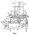
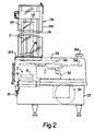
- a slicer 20 embodying the present invention is shown in the drawings. With particular reference to Figures 1, 2 and 3, the slicer 20 has a lower cabinet 22, and an upper cabinet 24 supported on the lower cabinet, and a product magazine 26, supported on the upper cabinet.
- the lower cabinet 22 houses and supports an internal frame 28 ( Figure 3), and a combination drive motor, transmission and brake unit 30. It also supports a control panel 31 and provides a product drop area D for receiving slices S of product P.
- a rotatable gear housing 32 is supported for rotation above the lower cabinet 22 on a vertical stationary tubular shaft 36 ( Figure 3) extend upwardly from the lower cabinet.
- a horizontal product support table 38 is supported for free rotation about the axis A1 of the tubular shaft 36 and is carried in rotation by the gear housing 32.
- a circular slicing blade 40 is carried by a vertical, rotating shaft 42 journaled in the gear housing 32, for rotation about an axis A2 parallel to and radially offset from the tubular shaft 36 and axis A1.
- Rotation of the gear housing 32 about the fixed tubular shaft 36 rotates the shaft 42 and blade 40 about the axis A2 and in addition orbits the blade and rotates the table 38 about the tubular shaft 36 and axis A1.
- the gear housing, table and blade are covered in use by the upper cabinet 24.
- the product is received on a conveying belt 49 and after a stack of slices of a desired height or weight is received, the belt is indexed to move the stack from the drop area and receives subsequent slices on an adjacent surface of the belt.
- the frame 28 which is directly secured to the lower cabinet, provides a horizontal support for the vertical tubular shaft 36, which is fixed in place to the frame by machine screws 50.
- a table support shaft 52 is freely rotatable and slidable within the fixed tubular shaft 36.
- the table 38 is firmly secured to a collar 54 at the top of the shaft 52, by screws 56.
- the table support shaft 52 is movable by a motor-driven screw jack 58 secured by a mounting bracket 59 to the bottom side of frame 28.
- the table support shaft 52 is connected to the jack through a lift cartridge assembly 60 connected to the lower end of the support shaft 52 through a bearing that allows relative rotation, but that prevents relative axial movement.
- a stationary gear 62 is keyed to the tubular shaft 36 within the gear housing 32, which is supported for rotation on the tubular shaft 36.
- the stationary gear 62 meshes with a smaller pinion 64 fixed to the lower end of the rotatable blade shaft 42 carried by the housing 32.
- a ring gear 66 is secured externally to the housing 32, as by screws 67, and is driven by a pinion 68 from the motor, transmission and brake unit 30.
- the brake serves to automatically stop the rotation of the pinion 68 when the power to the motor is turned off.
- the blade shaft 42 extends upward through the opening 46 in the table 38.
- the diameter of the blade 40 is greater than the radius of the table 38 and a recess 46a is provided in the central portion of the table so that the table can be raised to a level where its top surface 38a is flush with the top surface 40a of the knife.
- a shaft 69 extends downward from the table 38 and is received in a bore 70 in the gear housing.
- a sleeve bearing within the bore facilitates relative rotation and axial movement between the shaft 69 and the housing.
- the shaft 69 provides an interconnection between the gear housing and table that rotates the table with the gear housing while allowing vertical movement of the table relative to the gear housing and blade to adjust the thickness of slices cut from a product.
- the blade 40 is disk-shaped and is dished to provide a central cavity 74. At the top surface 40a, the blade is in the form of a radially narrow flat ring that lies in a horizontal plane, whereas the lower surface of the blade adjacent the cutting edge is inclined in an upward and radially outward direction.
- the blade 40 is secured in the center to the top of the shaft 42 by spaced screws 76.
- Spaced circular apertures 78 (4 in the preferred embodiment) are provided in the disk-like blade, located in the inclined or conical portion 40b, radially inward from the ring-like top surface 40a.
- a freely rotatable circular plate 80 is supported on the shaft 42, concentric with the blade, by a suitable bushing and nut assembly 82 and appropriate washers.
- the top surface 80a of the plate is essentially flush with the upper surface 40a of the blade and the lower surface 80b of the plate 80 is spaced from the central and conical portions of the blade 40 to form with the blade the cavity 74.
- the plate 80 has at its periphery, an outwardly and upwardly angled annular portion 84 that terminates in a vertical peripheral wall portion 85, from which a horizontal flange surface 86 extends radially, terminating in an upwardly and outwardly beveled suface 87.
- Surfaces 84a, 85a, 86a and 87a formed in the upper surface of the blade, just interiorly of the ring-like top surface 40a, are parallel to and slightly spaced from the surfaces 84-87 of the plate 80, forming respectively a frusto-conical surface a radial surface and a second frusto-conical surface.
- the facing surfaces form a labyrinthine passage from outside the blade and plate to the cavity 74 between the two.
- the labyrinthine passage facilitates relative rotation between the blade and plate, while inhibiting entry of particles of the product that is cut.
- Product particles that do move through the passage from outside the blade and plate into the cavity 74 tend to be moved by centrifugal force outward and tend to migrate peripherally about the blade and are thereby expelled from the cavity through the openings 78.
- the blade 40 During cutting, the blade 40, rotating and orbiting, slides relative to the product P as it moves through the product, to cut a slice therefrom.
- the annular top surface portion 40a being very narrow, provides little frictional resistance to such movement. Instead, the major portion of the product being sliced is supported on the freely rotatable plate 80. Since that plate is not driven, and instead tends to stay as much as possible stationary with the work product through frictional engagement, and in fact tends to counter rotate relative to the rotating table 38, there is relatively little sliding and hence little friction loss between the blade and plate and the work product. Thus, this construction reduces both surface smear of the product and power consumption.
- the gear housing is formed to facilitate detection of a particular rotational position by a proximity switch on the frame.
- an annular flange 90 ( Figures 3 and 5) extends downward from the lower surface of the housing and is surrounded by the ring gear 66.
- a notch 91 is formed in the lower surface of the flange, as best shown in Figure 5.
- the absence of the flange where the notch is located is sensed by a capacitive-type proximity switch 92 ( Figure 4), located in the position shown in Figure 4.
- the upper cabinet 24 that covers the table 38 and blade 40 is in the form of a shell that fits over the lower cabinet 22 and is supported by the frame 28 and secured thereto by four knobs 94 adjacent corners of the cabinet that screw into the frame.
- the upper cabinet overlies the drop area D and has an opening 98 ( Figure 3) through a top portion for the product to extend as it rests on the table 38.
- the upper cabinet has an opening 99 in the front surface, with a transparent cover to permit viewing of the drop area.
- the upper cabinet has a further opening 100 at the left end (as viewed in Figure 1) of the drop area, as best shown in Figure 3.
- the opening 100 permits removal of the product that has been cut, and facilitates entry and support of the conveyor 48 in the drop area.
- the product magazine 26 is supported on the upper cabinet 24 by an enlarged magazine base 102 ( Figures 1 and 2) that is located over the opening 98 and secured in place by two of the knobs 94.
- the magazine base 102 has an opening 104 that is aligned with the opening 98 in the upper cabinet. Approximately one-half of the opening 104 is surrounded by the magazine 26, which is an upright trough-shaped metal affair secured adjacent the bottom to the base 104, but with its bottom edge extending slightly below the base to adjacent the level of the upper surface of the blade 40.
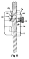
- a magazine door or cover 106 is secured to and pivoted along one vertical edge of the magazine by upper and lower pivot pins 107 as shown in Figures 6 and 7.
- the cover 106 carries a magnet 108 on a lower portion, that operates a proximity switch 109 carried by the frame 28 just beneath the upper cabinet (see Figure 1) located to underlie the magnet when the cover 106 is in a closed position.
- the upper cabinet carries a magnet 110 that operates a proximity switch 112 on the frame.
- the proximity switches 109, 112 are in series with a "power on" switch to the drive motor, so that only when the two proximity switches are closed by the presence of the magnets 108, 110, respectively, will the blade be operated.
- the upper cabinet must be in place over the lower cabinet, the magazine and magazine base must be in position over the upper cabinet, covering the opening 98, and the door 106 to the magazine must be in a closed position before the slicer can operate.
- the magazine 26 has two guide flanges 115, 116 that extend vertically the height of the magazine and outwardly from the open front of the trough-like shape. These flanges serve to guide vertical movement of a product follower 118 that engages the top or upper end of a product P in the magazine and urges the product downward.
- the follower is also held within the magazine by the guide flanges to retain the product in a vertical position against the back of the magazine, so the product does not move when contacted by the slicing blade.
- the product follower 118 has a relatively flat horizontal plate 120 that fits within the magazine.
- the plate has tines 121 extending downward from a lower surface, to engage the product.
- Two posts 122, 124 extend upward from the plate and engage the bottom edge of a generally flat, vertical body 126 that spans the transverse distance of the opening of the trough and that receives the flanges 115, 116 in vertical grooves 129, 130.
- the posts 122, 124 are connected to the body by rods that extend vertically through the body and are secured at the top of the body by nuts 127.
- the grooves 129, 130 each carry two bosses 131 adjacent the top and bottom, that define a slot 129a, 130a that closely receives the guide flanges 115, 116.
- a U-shaped handle 128 extends from one side 126a of the body 126. That side portion of the body extends through a narrow vertical gap G between the magazine 26 and the cover 106, when the cover is closed.
- the handle has a trigger latch 132 partially received in a vertical side slot 133 and pivoted to the body 126 by a cross-pin 134 ( Figures 6 and 7) extending across the side slot.
- the trigger latch has a latch portion 136 that extends laterally through an opening 135 into the groove 129 and into the path of the guide flange 115 under the force of a leaf spring 138 secured to the trigger latch and acting against the U-shaped handle.
- the weight of the follower will urge the product downward as slices are removed from the bottom end.
- the handle 128 engages the magazine base 102 and prevents the follower from going below the magazine base and into the path of the cutter blade.
- the jack screw 58 that raises, and lowers the table 38 is driven by an electric motor 140 ( Figure 3) supported by the bracket 59.
- a rack 141 carried vertically by the jack screw rotates a pinion 142 on the shaft of a potentiometer 143 that operates a gauge on the control panel 31 to indicate the position of the table and, hence, the thickness to which the slicer will cut slices from the product.
- the conveyor 48 is attached by a bracket 144 to one side of the lower cabinet 22 (see Figure 1 and 8) and extends through the opening 100 of the upper cabinet and into the drop area D, beneath the magazine.
- the conveyor is comprised of two separable parts, a drive part 145 and a product carrying part 146 supported on the drive part.
- the product carrying part has three idler rollers 148, 149, 150 and one drive roller 151, with the belt 49 trained about the rollers and an upper reach 49a supported by a horizontal plate 155.
- the drive roller 151 has an outwardly extending square stub shaft 158 ( Figure 9) that drives the roller.
- the drive part 145 of the conveyor has an electric motor drive 160 connected to a driving pulley 162. It has a driven pulley 164 connected to the driving pulley by a transmission belt 166.
- the driven pulley 164 is on a shaft 168 that has a square socket 169 and that is aligned with and receives the shaft 158. With this arrangement, the two parts 145, 146 can be easily separated by slidably separating the shafts 158, 168, which facilitates cleaning of the product carrying part 145.
- the electric motor drive 160 is controlled to allow either continuous operation or indexing movement to carry sliced product from the drop area within the upper cabinet to the end of the conveyor 101 that is outside the cabinet. The entire unit is easily removed from the slicer by lifting it from the bracket 144, when the conveyor is not required.
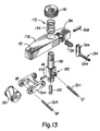
- a removable sharpener 172 for grinding and honing the blade 40 is shown in Figures 10-13.
- a small recess 174 is formed in the table 38 along the aperture 46 at the location best shown in Figure 4, to receive the sharpener.
- the recess extends peripherally approximately 15 angular degrees and is at that portion of the periphery of the aperture 46 that is diametrically opposite the blade shaft 42 relative to the axis A1, which places it radially at a location that is always inward of the magazine 26.
- Two vertical pins 176, 177 extend from the upper surface 38a of the table, one on each side of the recess to receive and locate the sharpener.
- the sharpener 172 has a support body 178 that spans the recess 174, a grinding drum 180 that fits within the recess, a clamp mechanism 182 that passes through the recess and engages the underside of the table, and a hone 184 that extends outward from the recess across the top edge of the blade.
- the body 178 has two apertures 186, 187 for slidably receiving the pins 176, 177.
- a shaft 190 of the clamp mechanism extends through the body and has a top knob 191 above the body and a locking pin 192 extending radially from the shaft below the body a sufficient distance to fit beneath the table. The shaft is rotatable and slidable in the body.
- a compression spring 194 about the shaft 190 acts between the body and knob to bias the pin 192 toward the underside of the table.
- the pin swings about the axis of the shaft 190 when the knob 191 is rotated.
- the pin when the pin is in a disengaged position, there is space in the recess for the pin to move through the recess from above the table 38 to below the table as the sharpener is placed on the pins.
- the knob 191 is then pressed toward the body 178 the pin moves below an abutment 196 ( Figure 11).
- the knob 45° By then rotating the knob 45°, the pin is moved into a notch 198 and retains the body on the pins and against the table top.
- the grinding drum 180 is attached to the shaft 190 beneath the body by a clevis-like pivoted arm 200 on a cross pin 201.
- a compression spring 202 acts between the shaft and arm to bias the arm and drum upward about the pin 201 toward the body 178.
- the drum and arm are located essentially within the thickness of the table and within the recess 174 in the disengaged position.
- the grinding drum When the shaft 190 is rotated 45° to engage the locking pin 192 in the notch 198, the grinding drum is moved out of the recess and into contact with the lower edge of the periphery of the cutter blade, with the axis A3 of the drum at 45° from a tangent to the blade edge where the drum contacts the blade and slightly inclined relative to the longitudinal axis of the shaft 190 an amount corresponding essentially to the bevel on the lower surface of the blade.
- the drum is freely rotatable about its axis A3 on a pin 203 and the arm 200 is biased upward by the spring 202 to engage the drum with the blade, so the drum rotates about its axis A3 when the blade is driven about its axis A2.
- the hone 184 has a rod 204 extending substantially radially of the blade, overlying the top surface 40a.
- the rod extends from a vertical member 206 ( Figure 13) pivoted on the body 178 by a horizontal pin 208 that extends at a right angle to the rod 204.
- the member 206 extends above the pivot pin and is urged toward the blade by a compression spring 210, which yieldably urges the hone against the edge and top surface of the blade.
- the door or cover 106 to the magazine is closed, the latch portion 136 is released by operating the trigger 132 and the product follower is then lowered into contact with the top of the product.
- the machine is now ready to be operated to slice the product by energizing the motor unit 30.
- the motor 140 is operated to move the shaft 52 and table 38 vertically.
- the drive motor 30 is then turned on and the gear housing 32 is driven in rotation about the stationary tubular shaft 36 and the fixed gear 62, causing the table 38 to rotate about axis A1 and the blade 40 to spin at a significantly faster rate about its central axis A2 as the blade orbits about the central axis A1 of the table.
- the rotation of the table and blade can be easily started, gaining momentum before the blade reaches the product.
- the blade intersects and passes through the product and the sliced piece drops through the opening 46 in the table 38 and into the product drop area D and onto the conveyor 48.
- the conveyor is in an indexing mode, several slices are stacked on the conveyor, one on top of the other, one piece being cut for each revolution of the table.
- the conveyor is then indexed and a second stack of slices formed adjacent the first, and so on.
Landscapes
- Life Sciences & Earth Sciences (AREA)
- Forests & Forestry (AREA)
- Engineering & Computer Science (AREA)
- Mechanical Engineering (AREA)
- Food-Manufacturing Devices (AREA)
- Formation And Processing Of Food Products (AREA)
- Details Of Cutting Devices (AREA)
- Meat, Egg Or Seafood Products (AREA)
- Finish Polishing, Edge Sharpening, And Grinding By Specific Grinding Devices (AREA)
- Crushing And Pulverization Processes (AREA)
Claims (17)
- Scheibenschneidmaschine (20) für Lebensmittel, mit einer Basis (22), einem auf der Basis vorgesehenen Halter (52), der relativ zu der Basis um eine erste Achse (A1) drehbar ist, einem kreisförmigen Messer (40), das von dem Halter getragen ist und relativ zu dem Halter um eine parallel zu der ersten Achse verlaufende zweite Achse (A2) drehbar ist, einem Tisch (38), der mit dem Halter um seinen Mittelpunkt (A1) drehbar ist und eine von dem Mittelpunkt (A1) versetzte Öffnung (46) aufweist, durch die die zweite Achse (A2) verläuft, wobei der Tisch und das Messer axial relativ zueinander verstellbar sind, einer Einrichtung (30) zum Drehen des Halters, einer Einrichtung (32) zum Drehen des Messers relativ zu dem Halter, einem Magazin (26), das relativ zu der Basis in der Nähe des Tisches befestigt ist und von der ersten Achse versetzt angeordnet ist sowie zum Halten eines Lebensmittels in Position für eine Bewegung in Richtung auf eine Lebensmittelfestlegefläche des Tisches zur Ausführung des Aufschneidvorgangs ausgelegt ist,
dadurch gekennzeichnet, daß ein bei der Öffnung befindlicher Bereich (174) des Tisches in einer radialen Position von dem Mittelpunkt (A1) angeordnet ist und sich nicht unter das Magazin erstreckt, wobei der Bereich (174) des Tisches an und quer zu der Lebensmittelfestlegefläche des Tisches Flächen (176, 177) aufweist, die mit einem abnehmbaren Messerschärfer (172) in Eingriff bringbar sind, wobei der Messerschärfer an der Oberseite des Tisches anbringbar ist und nach oben von dem Tisch abnehmbar ist und wobei der Messerschärfer einen Körper (178) mit einer Einrichtung (186, 187) zum Festlegen des Körpers relativ zu den Tischflächen (176, 177) aufweist und der Körper eine Schärffläche (180) unterhalb der oberen Oberfläche des Tisches zum Schärfen der Unterseite (406) des Messers (40) trägt. - Scheibenschneidmaschine nach Anspruch 1,
dadurch gekennzeichnet, daß der genannte Bereich des Tisches eine Aussparung (174) im Umfang der Öffnung beinhaltet, und daß die Scheibenschneidmaschine außerdem den teilweise in der Aussparung befindlichen Messerschärfer (172) beinhaltet. - Scheibenschneidmaschine nach Anspruch 1 oder 2,
dadurch gekennzeichnet, daß es sich bei der Einrichtung auf der Lebensmittelfestlegefläche des Tisches um zwei wegstehende Stifte (176, 177) handelt und sich der Messerschärferkörper (178) über die Aussparung hinwegerstreckt, daß die Festlegeeinrichtung die Stifte aufnehmende Öffnungen (186, 187) umfaßt, daß eine Klemmeinrichtung (182) an dem Körper an einer der Lebensmittelfestlegefläche entgegengesetzten Fläche des Tisches angreift, daß die Schärffläche (180) ein an dem Körper getragenes Element zur Ausführung einer Bewegung zischen einer innerhalb der Aussparung gelegenen Position und einer sich aus der Aussparung herauserstreckenden Position, in der das Messer daran angreifen kann, getragen ist, und daß über der oberen Oberfläche des Tisches eine Einrichtung (190, 191) zum Bewegen der Schärffläche zwischen den genannten Positionen vorgesehen ist. - Scheibenschneidmaschine nach Anspruch 3,
dadurch gekennzeichnet, daß die Einrichtung zum Bewegen der Schärffläche (180) auch die Klemmeinrichtung betätigt. - Scheibenschneidmaschine nach Anspruch 1, 2, 3 oder 4, gekennzeichnet durch eine Einrichtung (91, 92) zum Bestimmen einer Rotationsposition des Messers um die erste Achse während der Rotation des Halters und zum Stoppen der Rotation des Halters, wenn sich das Messer in einer Position befindet, in der es außer Ausrichtung mit dem Magazin (26) ist.
- Scheibenschneidmaschine nach Anspruch 5,
dadurch gekennzeichnet, daß die Einrichtung zum Drehen des Halters einen Elektromotor (30) beinhaltet, daß die Erfassungseinrichtung einen auf der Basis gehalterten Annäherungsschalter (92) beinhaltet, der eine vorbestimmte Position der sich um die erste Achse drehenden Vorrichtung erfaßt, daß ein Energieschalter für den Elektromotor vorgesehen ist, und daß eine auf den Betrieb des Energieschalters und des Annäherungsschalters ansprechende Bremseinrichtung (30) zum Stoppen des Halters vorgesehen ist. - Scheibenschneidmaschine nach einem der vorausgehenden Ansprüche, dadurch gekennzeichnet, daß es sich bei dem Messer um eine Scheibe (40) mit einer umfangsmäßig umlaufenden Schneidkante (40a) und einer schalenförmigen Kontur handelt, die zwischen einer Mittelplatte (80) und dem Messer einen Hohlraum (74) vorsieht, daß die Platte (80) ein umfangsmäßig umlaufendes Profil (84-87) aufweist und das Messer ein dieses umgebendes und komplemenentär zu diesem ausgebildetes Profil (84a, 85a, 86a, 87a) an einem von der Schneidkante radial nach innen verlagerten Bereich aufweist, und daß das umlaufende Profil und das dieses umschließende Profil geringfügig voneinander beabstandet sind und derart konfiguriert sind, daß sie eine labyrinthartige Passage zwischen dem Messer und der Platte von der Außenseite des Messers und der Platte in den zwischen dem Messer und der Platte vorhandenen Hohlraum bilden.
- Scheibenschneidmaschine nach Anspruch 7,
dadurch gekennzeichnet, daß das Messer umfangsmäßig voneinander beabstandete Öffnungen (78) aufweist, die sich unterhalb und in der Nähe des Umfangs der Platte in den Hohlraum (74) öffnen. - Scheibenschneidmaschine nach einem der vorausgehenden Ansprüche, dadurch gekennzeichnet, daß sich die erste Achse (A1) vertikal erstreckt und sich der Tisch (38) allgemein horizontal erstreckt und daß das Magazin (26) dazu ausgelegt ist, ein auf dem Tisch zum Aufschneiden gehaltenes Lebensmittel in einer aufrechten Position zu halten, sowie eine offene Hochkantseite (104), einen schwenkbaren Deckel (106) zum Schließen der Hochkantseite zum Festhalten des Produkts in dem Magazin, eine schmale Öffnung längs des Magazins, ein innerhalb des Magazins vorgesehenes und dieses entlangbewegbares Lebensmittel-Folgerglied (118) mit einer Einrichtung (132, 136) zum lösbaren Festhalten des Folgerglieds gegen eine nach unten gehende Bewegung, sowie einen außerhalb des Magazins und des Deckels befindlichen Mechanismus (128, 132) zum Betätigen der Festhalteeinrichtung umfaßt, wobei sich das Folgerglied teilweise durch die schmale Öffnung hindurcherstreckt.
- Scheibenschneidmaschine nach Anspruch 9,
dadurch gekennzeichnet, daß sich die schmale Öffnung zwischen dem Magazin und dem Deckel erstreckt, und daß das Folgerglied eine allgemein horizontale Platte (130) innerhalb des Magazins, ein das Folgeglied in einer angehobenen Position an einem oberen Ende des Magazins haltendes Verriegelungsglied (132) und ein von Hand betätigbares Verriegelungslöseglied (132) außerhalb des Magazins und des Deckels umfaßt. - Scheibenschneidmaschine nach einem der Ansprüche 1 bis 8,
dadurch gekennzeichnet, daß die Scheibenschneidmaschine eine abnehmbare Abdeckung (24) über der Basis, dem Halter, dem Messer und dem Tisch aufweist, daß die Abdeckung eine Öffnung für die Passage eines aufzuschneidenden Lebensmittels aufweist, daß das Magazin an der Basis lösbar gehaltert ist und eine offene Hochkantseite aufweist, daß eine Klappe (106) zum Schließen der offenen Hochkantseite an dem Magazin schwenkbar gehaltert ist, daß ein Annäherungsschalter-Betätigungsglied (108) an der Klappe gehaltert ist, und daß sich ein Annhäherungsschalter (109) auf der Basis an einer Stelle befindet, an der eine Betätigung durch das das Betätigungsglied nur bei geschlossener Klappe erfolgt, wobei dieser Annäherungsschalter einen Betrieb der Scheibenschneidmaschine nur bei dessen Betätigung ermöglicht. - Scheibenschneidmaschine nach einem der vorausgehenden Ansprüche, gekennzeichnet durch eine an der Basis angebrachte Fördereinrichtung (48) zum Aufnehmen und Befördern von aufgeschnittenem Material, wobei die Fördereinrichtung ein um Rollen geführtes Förderband (49) aufweist, von denen eine eine Antriebsrolle (151) ist, wobei sich ein Bereich des Förderbands unterhalb eines oder des Magazins (26) befindet und ein Drehantriebselement (168) mit der Antriebsrolle zur Erleichterung der Abnahme der Fördereinrichtung von der Basis lösbar verbunden ist.
- Scheibenschneidmaschine nach einem der vorausgehenden Ansprüche, gekennzeichnet durch einen ersten Elektromotor (30) zum Drehen des Halters relativ zu dem Ständer, einen zweiten Elektromotor (140) und eine von dem zweiten Motor angetriebene Einrichtung (141, 142) zum Bewegen des Tisches längs der ersten Achse relativ zu dem Messer, wobei der Tisch relativ zu der angetriebenen Einrichtung drehbar ist.
- Scheibenschneidmaschine nach Anspruch 13,
gekennzeichnet durch ein Potentiometer (143), eine Transmissionseinrichtung zum Einstellen des Potentiometers ansprechend auf eine axiale Bewegung der drehbaren Welle, und durch ein elektrisch betriebenes und auf das Potentiometer ansprechendes Meßinstrument zum Anzeigen der Position des Tisches relativ zu dem Messer. - Scheibenschneidmaschine nach einem der Ansprüche 1 bis 14, bei der das Messer (40) kreisförmig und zur Schaffung eines zentralen Hohlraums (74) schalenförmig ausgebildet ist, wobei das Messer eine relativ schmale ringförmige planare Stirnfläche (40a) aufweist, deren Außenumfang eine Schneidkante bildet und deren Innenumfang (84a, 85a, 86a, 87a) zum Zusammenwirken mit einer drehbaren kreisförmigen Mittelplatte (80) ausgelegt ist,
dadurch gekennzeichnet, daß der Innenumfang (84a, 85a, 86a, 87a) aneinander angrenzende konzentrische Rotationsflächen (84a-87a) aufweist, die in unterschiedlichen Abständen von dem Mittelpunkt (A2) des Messers sowie in unterchiedlichen axialen Abständen von der planaren Stirnfläche angeordnet sind und zum Teil eine labyrinthartige Passage definieren, die zum Verhindern einer axialen Bewegung von Lebensmittelteilchen von der planaren Stirnfläche den Innenumfang entlang ausgelegt ist. - Scheibenschneidmaschine nach Anspruch 15,
dadurch gekennzeichnet, daß das Messer (40) umfangsmäßig voneinander beabstandete Öffnungen (78) aufweist, die sich radial innerhalb von der ringförmigen planaren Stirnfläche (40a) und dem Innenumfang durch das Messer hindurch in den Hohlraum (74) öffnen. - Scheibenschneidmaschine nach Anspruch 15 oder 16,
dadurch gekennzeichnet, daß die aneinandergrenzenden konzentrischen Flächen eine erste kegelstumpfförmige Fläche (84a), eine zylindrische Fläche (85a), eine radiale Fläche (86a) und eine zweite kegelstumpfförmige Fläche (87a) beinhalten und daß das Messer eine dritte, allgemein kegelstumpfförmige Fläche (40b) besitzt, die in bezug auf die ringförmige planare Stirnfläche (40a) in einem Winkel angeordnet ist und diese an der Schneidkante schneidet.
Priority Applications (2)
| Application Number | Priority Date | Filing Date | Title |
|---|---|---|---|
| EP90111647A EP0395123B1 (de) | 1985-05-17 | 1986-04-18 | Rotierende Aufschnitt-Schneidvorrichtung für Nahrungsmittel |
| AT86302956T ATE74306T1 (de) | 1985-05-17 | 1986-04-18 | Scheibenschneidmaschine fuer lebensmittel mit rotierendem messer. |
Applications Claiming Priority (2)
| Application Number | Priority Date | Filing Date | Title |
|---|---|---|---|
| US06/735,435 US4685364A (en) | 1985-05-17 | 1985-05-17 | Rotary slicer for comestible products |
| US735435 | 1985-05-17 |
Related Child Applications (2)
| Application Number | Title | Priority Date | Filing Date |
|---|---|---|---|
| EP90111647A Division EP0395123B1 (de) | 1985-05-17 | 1986-04-18 | Rotierende Aufschnitt-Schneidvorrichtung für Nahrungsmittel |
| EP90111647.5 Division-Into | 1986-04-18 |
Publications (3)
| Publication Number | Publication Date |
|---|---|
| EP0202777A2 EP0202777A2 (de) | 1986-11-26 |
| EP0202777A3 EP0202777A3 (en) | 1987-03-04 |
| EP0202777B1 true EP0202777B1 (de) | 1992-04-01 |
Family
ID=24955791
Family Applications (2)
| Application Number | Title | Priority Date | Filing Date |
|---|---|---|---|
| EP86302956A Expired - Lifetime EP0202777B1 (de) | 1985-05-17 | 1986-04-18 | Scheibenschneidmaschine für Lebensmittel mit rotierendem Messer |
| EP90111647A Expired - Lifetime EP0395123B1 (de) | 1985-05-17 | 1986-04-18 | Rotierende Aufschnitt-Schneidvorrichtung für Nahrungsmittel |
Family Applications After (1)
| Application Number | Title | Priority Date | Filing Date |
|---|---|---|---|
| EP90111647A Expired - Lifetime EP0395123B1 (de) | 1985-05-17 | 1986-04-18 | Rotierende Aufschnitt-Schneidvorrichtung für Nahrungsmittel |
Country Status (8)
| Country | Link |
|---|---|
| US (1) | US4685364A (de) |
| EP (2) | EP0202777B1 (de) |
| JP (1) | JPS61265296A (de) |
| KR (1) | KR860008842A (de) |
| AT (2) | ATE74306T1 (de) |
| CA (1) | CA1277213C (de) |
| DE (2) | DE3684634D1 (de) |
| DK (1) | DK226886A (de) |
Families Citing this family (54)
| Publication number | Priority date | Publication date | Assignee | Title |
|---|---|---|---|---|
| DK482687A (da) * | 1986-09-17 | 1988-03-18 | Omori Machinery | Skriveskaeringsmaskine |
| FR2605208B1 (fr) * | 1986-10-15 | 1989-01-27 | Dito Sama | Machine destinee a couper des produits alimentaires, tels que notamment des legumes |
| DE3713536A1 (de) * | 1987-04-22 | 1988-11-10 | Guenther Weber | Antriebs- und lageranordnung fuer den schneidkopf einer circularschneidmaschine |
| DE9205721U1 (de) * | 1992-04-29 | 1993-03-25 | Natec Reich, Summer GmbH & Co KG, 8996 Opfenbach | Schließblech für eine Schneidemaschine zum Schneiden von Lebensmittelprodukten |
| US6267033B1 (en) * | 1992-10-29 | 2001-07-31 | Kraft Foods, Inc. | Close tolerance food slicing apparatus, blade and method |
| US5988033A (en) * | 1992-10-29 | 1999-11-23 | Kraft Foods, Inc. | Food slicing apparatus, blade and method |
| US5320014A (en) * | 1992-10-29 | 1994-06-14 | Oscar Mayer Foods Corporation | Yield improving continuous food slicing method and apparatus |
| EP0635341A1 (de) * | 1993-07-15 | 1995-01-25 | Gec Avery Limited | Sicherheitsvorrichtung für eine elektrische Aufschnitt-Schneidemaschine |
| US5377571A (en) * | 1993-10-19 | 1995-01-03 | Josephs; Harold | Safety guard system for band saws and similar equipment |
| US5649463A (en) * | 1994-10-11 | 1997-07-22 | Formax, Inc. | Slicing station for a food loaf slicing machine |
| US5591072A (en) * | 1995-04-10 | 1997-01-07 | Premark Feg Corporation | Sharpening device for food slicer |
| US5687626A (en) * | 1995-12-15 | 1997-11-18 | Premark Feg L.L.C. | Food product slicer having an interlock mechanism |
| US5974934A (en) * | 1997-10-20 | 1999-11-02 | Woods; Charles | Apparatus for making a bowl from a loaf of bread |
| DE19820269C2 (de) * | 1998-05-07 | 2000-06-21 | Uwe Reifenhaeuser | Vorrichtung zum Schneiden eines Gutsstrangs in Scheiben |
| US7073421B1 (en) * | 2000-04-29 | 2006-07-11 | Itw Food Equipment Group Llc | Slicing machine, and method of use and components thereof |
| AU4687800A (en) * | 1999-04-30 | 2000-11-17 | Berkel Incorporated | Slicing machine, and method of use and components thereof |
| US6209438B1 (en) | 1999-12-22 | 2001-04-03 | Premark Feg L.L.C. | Interlock mechanism for a slicer |
| US7234382B2 (en) | 2000-05-16 | 2007-06-26 | Premark Feg L.L.C. | Slicer with unitary handle |
| USD463713S1 (en) | 2000-05-17 | 2002-10-01 | Premark Feg L.L.C. | Tray for a slicer |
| US20040040428A1 (en) * | 2002-06-19 | 2004-03-04 | Deyoung Perry R. | Garlic bread slicer |
| ATE357594T1 (de) * | 2004-02-10 | 2007-04-15 | Gamesa Eolica S A Soc Uniperso | Prüfstand für windkraftanlagen |
| US7493841B1 (en) * | 2005-01-19 | 2009-02-24 | Kaplan Robert E | Slicer |
| US7549363B2 (en) * | 2005-08-26 | 2009-06-23 | Premark Feg L.L.C. | Product table for a food slicer with hollow peripheral reinforcements |
| US20070044621A1 (en) * | 2005-08-26 | 2007-03-01 | Rote Scott J | Top mounted operator interface for a food slicer |
| US20070044627A1 (en) * | 2005-08-26 | 2007-03-01 | Clem Todd L | Speed and stroke control method and apparatus for a product table of a food slicer |
| US20070044626A1 (en) * | 2005-08-26 | 2007-03-01 | Bondarowicz Frank A | Overmolded food product table support arm for a food slicer |
| US20070044612A1 (en) * | 2005-08-26 | 2007-03-01 | Somal Hardev S | Gage plate adjustment mechanism for a food slicer |
| US20070044628A1 (en) * | 2005-08-26 | 2007-03-01 | Rote Scott J | Rear pivot pusher for a food slicer with clearance position |
| US7832317B2 (en) * | 2005-08-26 | 2010-11-16 | Premark Feg L.L.C. | Gage plate alignment mechanism and method for a food slicer |
| US8043142B2 (en) * | 2005-08-26 | 2011-10-25 | Premark Feg L.L.C. | Sharpener carried by the product table of a food slicer |
| US7637191B2 (en) * | 2005-08-26 | 2009-12-29 | Premark Feg L.L.C. | Product table lock for a food slicer |
| US20070142959A1 (en) * | 2005-12-19 | 2007-06-21 | Rummel Samuel A | Food product slicer with automatic indication of when to sharpen knife |
| US7134937B1 (en) | 2005-12-19 | 2006-11-14 | Premark Feg L.L.C. | Food product slicer with knife sharpener and associated knife guard |
| US7487702B2 (en) | 2005-12-19 | 2009-02-10 | Premark Feg L.L.C. | Food product slicer with removable ring guard cover |
| US7464632B2 (en) * | 2006-02-07 | 2008-12-16 | Premark Feg L.L.C. | Product fence for a food slicer |
| CN2905315Y (zh) * | 2006-04-25 | 2007-05-30 | 南京德朔实业有限公司 | 锯片的护罩装置 |
| JP2008030149A (ja) * | 2006-07-28 | 2008-02-14 | Nihon Career Ind Co Ltd | 食肉スライサー |
| DE102006043697A1 (de) * | 2006-09-18 | 2008-03-27 | Weber Maschinenbau Gmbh & Co. Kg | Verstelleinheit |
| JP5023373B2 (ja) * | 2006-10-23 | 2012-09-12 | 株式会社日本キャリア工業 | 食肉スライサー |
| US8549966B2 (en) * | 2007-10-22 | 2013-10-08 | Formax, Inc. | Output conveyor for a food article slicing machine |
| US8220383B2 (en) | 2008-04-15 | 2012-07-17 | Premark Feg L.L.C. | Food product slicer with timed sharpening operation |
| US20100064872A1 (en) * | 2008-09-12 | 2010-03-18 | Anatoly Gosis | Product fence for food slicer |
| US20100089254A1 (en) * | 2008-10-14 | 2010-04-15 | Anatoly Gosis | Food slicer and associated food product pusher |
| DE102009011399A1 (de) * | 2009-03-03 | 2010-09-09 | Weber Maschinenbau Gmbh Breidenbach | Schneidvorrichtung |
| DE102009011398A1 (de) * | 2009-03-03 | 2010-09-09 | Weber Maschinenbau Gmbh Breidenbach | Schneidvorrichtung |
| JP5024769B2 (ja) * | 2009-08-05 | 2012-09-12 | 株式会社日本キャリア工業 | 食肉スライサー |
| DE102010034360A1 (de) * | 2010-06-11 | 2011-12-15 | CFS Bühl GmbH | Verfahren und Vorrichtung zur Schneidspalteinstellung einer Aufschneidevorrichtung |
| FR3004254B1 (fr) * | 2013-04-08 | 2015-05-15 | Snecma | Installation de calibrage de jauge de mesure de contraintes |
| US20190232515A1 (en) * | 2018-01-26 | 2019-08-01 | Gunntech Manufacturing, Inc. | Portable Scoring and Slicing Machine |
| US10773893B2 (en) | 2018-06-26 | 2020-09-15 | Provisur Technologies, Inc. | Shuttle conveyor systems for use with a patty forming machine |
| DE102019135165B4 (de) * | 2019-12-19 | 2025-11-13 | Tvi Entwicklung Und Produktion Gmbh | Schneideinheit und Aufschneide-Maschine mit einer solchen Schneideinheit |
| CN112933759B (zh) * | 2021-02-22 | 2023-03-28 | 佛山市顺德区三兄弟机械制造有限公司 | 一种新能源汽车空调滤芯毛边去除设备 |
| CA3145602C (en) * | 2022-01-14 | 2026-02-03 | Les Promotions Atlantiques Inc. | Foldable manual food-slicing apparatus and corresponding method |
| DE102023112460A1 (de) * | 2023-05-11 | 2024-11-14 | Multivac Sepp Haggenmüller Se & Co. Kg | Aufschneide-Maschine mit vorfixierbarer Messer-Montagevorrichtung |
Family Cites Families (30)
| Publication number | Priority date | Publication date | Assignee | Title |
|---|---|---|---|---|
| AT41096B (de) * | 1909-02-26 | 1910-02-25 | Leo Anschel | Scheibenschneidemaschine mit umlaufendem Kreismesser. |
| US1263450A (en) * | 1914-06-16 | 1918-04-23 | Hyman Maimin | Sharpening attachment for cloth-cutting machines. |
| US1366568A (en) * | 1918-05-23 | 1921-01-25 | Knapp Frederick Henry | Ear-butting machine |
| US1559468A (en) * | 1923-03-08 | 1925-10-27 | Charles N Sowden | Slicing machine |
| US1607879A (en) * | 1924-08-15 | 1926-11-23 | William J Drucker | Slicing-machine knife |
| DE413276C (de) * | 1924-08-22 | 1925-05-04 | Cornelius Job Lensvelt | Aufschnittschneidemaschine |
| US1907620A (en) * | 1926-11-05 | 1933-05-09 | Us Slicing Machine Co | Machine for slicing meat containing bones |
| US2166648A (en) * | 1937-12-09 | 1939-07-18 | Eugene Fruit Growers Ass | Slicing machine |
| US2193979A (en) * | 1938-08-24 | 1940-03-19 | Mundet Cork Corp | Cutting machine |
| US2234432A (en) * | 1940-05-15 | 1941-03-11 | Galio Mario | Machine for forming plastic materials |
| US2528914A (en) * | 1942-08-27 | 1950-11-07 | Roest Arie | Slicing machine having cutter disk with planetary movement |
| US2414152A (en) * | 1943-05-20 | 1947-01-14 | Aldrich L Jackson | Automatic food slicer and slice counting machine |
| US2472876A (en) * | 1944-04-21 | 1949-06-14 | Us Slicing Machine Co | Rotary disk knife |
| US2617454A (en) * | 1945-07-09 | 1952-11-11 | Beacon Machine Works | Rod disk cutting machine |
| US3130621A (en) * | 1961-11-17 | 1964-04-28 | Harry C Else | Orbiting metal cutter |
| US3161215A (en) * | 1961-11-28 | 1964-12-15 | Great Lakes Stamp & Mfg Co Inc | Slicing machine |
| US3194289A (en) * | 1962-06-18 | 1965-07-13 | Robert A Lundell | High production slicing machine |
| US3428102A (en) * | 1965-10-13 | 1969-02-18 | Worthington Foods Inc | Slicing machine with slice arranger |
| US3406486A (en) * | 1965-12-13 | 1968-10-22 | Bettcher Industries | Sharpening device for rotary knives |
| US3530915A (en) * | 1967-10-28 | 1970-09-29 | Nantsune Tekko Kk | Slicer |
| US3590678A (en) * | 1969-07-31 | 1971-07-06 | Gen Mills Inc | Extrusion apparatus with a cutting mechanism having means to stop the cutter at a predetermined position |
| US3821913A (en) * | 1972-09-28 | 1974-07-02 | Chemetron Corp | Apparatus for accumulating stacks of sliced material |
| US3867858A (en) * | 1973-07-30 | 1975-02-25 | Gorton Corp | Frozen fish cutter |
| US3842698A (en) * | 1973-09-11 | 1974-10-22 | C Fitch | Slicing machine for slicing a food product or the like |
| DE2515062A1 (de) * | 1974-04-09 | 1975-10-23 | Westrex Co Ltd | Verfahren und vorrichtung zum gesteuerten spulen eines endlosen bandes, insbesondere eines films |
| US3972256A (en) * | 1975-05-30 | 1976-08-03 | Ross Henry M | Meat slicer |
| US4177703A (en) * | 1978-04-17 | 1979-12-11 | Cavier Adolf J J F | Slicing machine for salmon |
| US4428263A (en) * | 1981-10-08 | 1984-01-31 | Formax, Inc. | Food loaf slicing machine |
| DE3214464A1 (de) * | 1982-04-20 | 1983-10-27 | Berkel Patent Nv | Aufschnittschneidemaschine mit einem schleifzeug fuer das rotierende rundmesser |
| JPS5981098A (ja) * | 1982-11-01 | 1984-05-10 | 株式会社渡辺鉄工所 | 食品スライサ−の刃物カバ−の安全装置 |
-
1985
- 1985-05-17 US US06/735,435 patent/US4685364A/en not_active Expired - Fee Related
-
1986
- 1986-04-18 AT AT86302956T patent/ATE74306T1/de not_active IP Right Cessation
- 1986-04-18 DE DE8686302956T patent/DE3684634D1/de not_active Expired - Fee Related
- 1986-04-18 AT AT90111647T patent/ATE117614T1/de not_active IP Right Cessation
- 1986-04-18 DE DE3650216T patent/DE3650216T2/de not_active Expired - Fee Related
- 1986-04-18 EP EP86302956A patent/EP0202777B1/de not_active Expired - Lifetime
- 1986-04-18 EP EP90111647A patent/EP0395123B1/de not_active Expired - Lifetime
- 1986-05-02 CA CA000508326A patent/CA1277213C/en not_active Expired - Fee Related
- 1986-05-07 KR KR1019860003533A patent/KR860008842A/ko not_active Withdrawn
- 1986-05-16 DK DK226886A patent/DK226886A/da not_active Application Discontinuation
- 1986-05-17 JP JP61113406A patent/JPS61265296A/ja active Pending
Also Published As
| Publication number | Publication date |
|---|---|
| CA1277213C (en) | 1990-12-04 |
| KR860008842A (ko) | 1986-12-18 |
| EP0395123B1 (de) | 1995-01-25 |
| EP0395123A3 (de) | 1991-04-17 |
| DE3650216D1 (de) | 1995-03-09 |
| ATE117614T1 (de) | 1995-02-15 |
| EP0202777A2 (de) | 1986-11-26 |
| DE3684634D1 (de) | 1992-05-07 |
| US4685364A (en) | 1987-08-11 |
| EP0395123A2 (de) | 1990-10-31 |
| DE3650216T2 (de) | 1995-06-29 |
| EP0202777A3 (en) | 1987-03-04 |
| ATE74306T1 (de) | 1992-04-15 |
| JPS61265296A (ja) | 1986-11-25 |
| DK226886A (da) | 1986-11-18 |
| DK226886D0 (da) | 1986-05-16 |
Similar Documents
| Publication | Publication Date | Title |
|---|---|---|
| EP0202777B1 (de) | Scheibenschneidmaschine für Lebensmittel mit rotierendem Messer | |
| EP2204268B1 (de) | Aufschnittmaschine | |
| US4273013A (en) | Slicing machine | |
| EP2677904B1 (de) | Lebensmittelverarbeitungsvorrichtung mit einem extern betätigten einstellmechanismus | |
| US3782230A (en) | Comestible slicing apparatus | |
| US4471915A (en) | Food processor having enlarged feed tube with safety guard | |
| US4412483A (en) | Spiral meat slicer | |
| EP2599417B1 (de) | Lebensmittelverarbeitungsvorrichtung mit deckelmontiertem Einstellmechanismus | |
| EP2599416A2 (de) | Extern betriebener Einstellmechanismus für eine Lebensmittelverarbeitungsmaschine | |
| US4002298A (en) | Cheese grating machine | |
| US2414152A (en) | Automatic food slicer and slice counting machine | |
| US4332190A (en) | Spiral meat slicer | |
| US3951054A (en) | Meat slicer | |
| US3587689A (en) | Comestible slicing apparatus | |
| US5104050A (en) | Food processor having axially translatable blade spindle coupled for rotation to motor driven shaft | |
| US4610398A (en) | Cheese shredding machine and blade therefor | |
| US3831475A (en) | Comestible slicing apparatus | |
| MX2008002717A (es) | Afilador comprendido en la plancha de producto de una rebanadora de alimentos. | |
| US4177703A (en) | Slicing machine for salmon | |
| US4062262A (en) | Slicing machines | |
| US5799401A (en) | Bagel dough extractor | |
| US2796103A (en) | Food slicing machine | |
| US3878604A (en) | Can opener with automatic cutter disengagement | |
| US4237759A (en) | Rotary slicer | |
| GB2230428A (en) | Food processor |
Legal Events
| Date | Code | Title | Description |
|---|---|---|---|
| PUAI | Public reference made under article 153(3) epc to a published international application that has entered the european phase |
Free format text: ORIGINAL CODE: 0009012 |
|
| AK | Designated contracting states |
Kind code of ref document: A2 Designated state(s): AT BE CH DE FR GB IT LI LU NL SE |
|
| PUAL | Search report despatched |
Free format text: ORIGINAL CODE: 0009013 |
|
| AK | Designated contracting states |
Kind code of ref document: A3 Designated state(s): AT BE CH DE FR GB IT LI LU NL SE |
|
| 17P | Request for examination filed |
Effective date: 19870827 |
|
| 17Q | First examination report despatched |
Effective date: 19881110 |
|
| RIN1 | Information on inventor provided before grant (corrected) |
Inventor name: WUNDER, WILLIAM G. Inventor name: KIRSCH, RICHARD C. Inventor name: ROBLIN, WILLIAM J. III Inventor name: SCHEFLOW, OLIVER W. |
|
| ITF | It: translation for a ep patent filed | ||
| GRAA | (expected) grant |
Free format text: ORIGINAL CODE: 0009210 |
|
| AK | Designated contracting states |
Kind code of ref document: B1 Designated state(s): AT BE CH DE FR GB IT LI LU NL SE |
|
| PG25 | Lapsed in a contracting state [announced via postgrant information from national office to epo] |
Ref country code: SE Effective date: 19920401 Ref country code: NL Effective date: 19920401 Ref country code: LI Effective date: 19920401 Ref country code: CH Effective date: 19920401 Ref country code: BE Effective date: 19920401 Ref country code: AT Effective date: 19920401 |
|
| REF | Corresponds to: |
Ref document number: 74306 Country of ref document: AT Date of ref document: 19920415 Kind code of ref document: T |
|
| XX | Miscellaneous (additional remarks) |
Free format text: TEILANMELDUNG 90111647.5 EINGEREICHT AM 18/04/86. |
|
| PG25 | Lapsed in a contracting state [announced via postgrant information from national office to epo] |
Ref country code: LU Free format text: LAPSE BECAUSE OF NON-PAYMENT OF DUE FEES Effective date: 19920430 |
|
| REF | Corresponds to: |
Ref document number: 3684634 Country of ref document: DE Date of ref document: 19920507 |
|
| ET | Fr: translation filed | ||
| REG | Reference to a national code |
Ref country code: CH Ref legal event code: PL |
|
| NLV1 | Nl: lapsed or annulled due to failure to fulfill the requirements of art. 29p and 29m of the patents act | ||
| PLBE | No opposition filed within time limit |
Free format text: ORIGINAL CODE: 0009261 |
|
| STAA | Information on the status of an ep patent application or granted ep patent |
Free format text: STATUS: NO OPPOSITION FILED WITHIN TIME LIMIT |
|
| PGFP | Annual fee paid to national office [announced via postgrant information from national office to epo] |
Ref country code: FR Payment date: 19930310 Year of fee payment: 8 |
|
| 26N | No opposition filed | ||
| ITTA | It: last paid annual fee | ||
| PG25 | Lapsed in a contracting state [announced via postgrant information from national office to epo] |
Ref country code: FR Effective date: 19941229 |
|
| REG | Reference to a national code |
Ref country code: FR Ref legal event code: ST |
|
| PGFP | Annual fee paid to national office [announced via postgrant information from national office to epo] |
Ref country code: GB Payment date: 19960319 Year of fee payment: 11 |
|
| PGFP | Annual fee paid to national office [announced via postgrant information from national office to epo] |
Ref country code: DE Payment date: 19960325 Year of fee payment: 11 |
|
| PG25 | Lapsed in a contracting state [announced via postgrant information from national office to epo] |
Ref country code: GB Effective date: 19970418 |
|
| GBPC | Gb: european patent ceased through non-payment of renewal fee |
Effective date: 19970418 |
|
| PG25 | Lapsed in a contracting state [announced via postgrant information from national office to epo] |
Ref country code: DE Free format text: LAPSE BECAUSE OF NON-PAYMENT OF DUE FEES Effective date: 19980101 |
|
| PG25 | Lapsed in a contracting state [announced via postgrant information from national office to epo] |
Ref country code: IT Free format text: LAPSE BECAUSE OF NON-PAYMENT OF DUE FEES;WARNING: LAPSES OF ITALIAN PATENTS WITH EFFECTIVE DATE BEFORE 2007 MAY HAVE OCCURRED AT ANY TIME BEFORE 2007. THE CORRECT EFFECTIVE DATE MAY BE DIFFERENT FROM THE ONE RECORDED. Effective date: 20050418 |