EP0202209B1 - Werkzeug und Einsatz, z.B. zum Drehen - Google Patents
Werkzeug und Einsatz, z.B. zum Drehen Download PDFInfo
- Publication number
- EP0202209B1 EP0202209B1 EP86850157A EP86850157A EP0202209B1 EP 0202209 B1 EP0202209 B1 EP 0202209B1 EP 86850157 A EP86850157 A EP 86850157A EP 86850157 A EP86850157 A EP 86850157A EP 0202209 B1 EP0202209 B1 EP 0202209B1
- Authority
- EP
- European Patent Office
- Prior art keywords
- insert
- inner disc
- hole
- shank
- disc
- Prior art date
- Legal status (The legal status is an assumption and is not a legal conclusion. Google has not performed a legal analysis and makes no representation as to the accuracy of the status listed.)
- Expired - Lifetime
Links
Images


Classifications
-
- B—PERFORMING OPERATIONS; TRANSPORTING
- B23—MACHINE TOOLS; METAL-WORKING NOT OTHERWISE PROVIDED FOR
- B23B—TURNING; BORING
- B23B27/00—Tools for turning or boring machines; Tools of a similar kind in general; Accessories therefor
- B23B27/14—Cutting tools of which the bits or tips or cutting inserts are of special material
- B23B27/16—Cutting tools of which the bits or tips or cutting inserts are of special material with exchangeable cutting bits or cutting inserts, e.g. able to be clamped
- B23B27/1603—Cutting tools of which the bits or tips or cutting inserts are of special material with exchangeable cutting bits or cutting inserts, e.g. able to be clamped with specially shaped plate-like exchangeable cutting inserts, e.g. chip-breaking groove
- B23B27/1611—Cutting tools of which the bits or tips or cutting inserts are of special material with exchangeable cutting bits or cutting inserts, e.g. able to be clamped with specially shaped plate-like exchangeable cutting inserts, e.g. chip-breaking groove characterised by having a special shape
-
- B—PERFORMING OPERATIONS; TRANSPORTING
- B23—MACHINE TOOLS; METAL-WORKING NOT OTHERWISE PROVIDED FOR
- B23B—TURNING; BORING
- B23B2200/00—Details of cutting inserts
- B23B2200/16—Supporting or bottom surfaces
- B23B2200/165—Supporting or bottom surfaces with one or more grooves
-
- B—PERFORMING OPERATIONS; TRANSPORTING
- B23—MACHINE TOOLS; METAL-WORKING NOT OTHERWISE PROVIDED FOR
- B23B—TURNING; BORING
- B23B2205/00—Fixation of cutting inserts in holders
- B23B2205/04—Fixation screws, bolts or pins of particular form
-
- B—PERFORMING OPERATIONS; TRANSPORTING
- B23—MACHINE TOOLS; METAL-WORKING NOT OTHERWISE PROVIDED FOR
- B23B—TURNING; BORING
- B23B2250/00—Compensating adverse effects during turning, boring or drilling
- B23B2250/12—Cooling and lubrication
-
- Y—GENERAL TAGGING OF NEW TECHNOLOGICAL DEVELOPMENTS; GENERAL TAGGING OF CROSS-SECTIONAL TECHNOLOGIES SPANNING OVER SEVERAL SECTIONS OF THE IPC; TECHNICAL SUBJECTS COVERED BY FORMER USPC CROSS-REFERENCE ART COLLECTIONS [XRACs] AND DIGESTS
- Y10—TECHNICAL SUBJECTS COVERED BY FORMER USPC
- Y10T—TECHNICAL SUBJECTS COVERED BY FORMER US CLASSIFICATION
- Y10T407/00—Cutters, for shaping
- Y10T407/19—Rotary cutting tool
- Y10T407/1952—Having peripherally spaced teeth
- Y10T407/1962—Specified tooth shape or spacing
- Y10T407/1964—Arcuate cutting edge
-
- Y—GENERAL TAGGING OF NEW TECHNOLOGICAL DEVELOPMENTS; GENERAL TAGGING OF CROSS-SECTIONAL TECHNOLOGIES SPANNING OVER SEVERAL SECTIONS OF THE IPC; TECHNICAL SUBJECTS COVERED BY FORMER USPC CROSS-REFERENCE ART COLLECTIONS [XRACs] AND DIGESTS
- Y10—TECHNICAL SUBJECTS COVERED BY FORMER USPC
- Y10T—TECHNICAL SUBJECTS COVERED BY FORMER US CLASSIFICATION
- Y10T407/00—Cutters, for shaping
- Y10T407/22—Cutters, for shaping including holder having seat for inserted tool
- Y10T407/2272—Cutters, for shaping including holder having seat for inserted tool with separate means to fasten tool to holder
- Y10T407/2274—Apertured tool
- Y10T407/2276—Apertured tool with means projecting through aperture to force tool laterally against reaction surface
-
- Y—GENERAL TAGGING OF NEW TECHNOLOGICAL DEVELOPMENTS; GENERAL TAGGING OF CROSS-SECTIONAL TECHNOLOGIES SPANNING OVER SEVERAL SECTIONS OF THE IPC; TECHNICAL SUBJECTS COVERED BY FORMER USPC CROSS-REFERENCE ART COLLECTIONS [XRACs] AND DIGESTS
- Y10—TECHNICAL SUBJECTS COVERED BY FORMER USPC
- Y10T—TECHNICAL SUBJECTS COVERED BY FORMER US CLASSIFICATION
- Y10T407/00—Cutters, for shaping
- Y10T407/22—Cutters, for shaping including holder having seat for inserted tool
- Y10T407/2272—Cutters, for shaping including holder having seat for inserted tool with separate means to fasten tool to holder
- Y10T407/228—Rotatable cam clamp element
-
- Y—GENERAL TAGGING OF NEW TECHNOLOGICAL DEVELOPMENTS; GENERAL TAGGING OF CROSS-SECTIONAL TECHNOLOGIES SPANNING OVER SEVERAL SECTIONS OF THE IPC; TECHNICAL SUBJECTS COVERED BY FORMER USPC CROSS-REFERENCE ART COLLECTIONS [XRACs] AND DIGESTS
- Y10—TECHNICAL SUBJECTS COVERED BY FORMER USPC
- Y10T—TECHNICAL SUBJECTS COVERED BY FORMER US CLASSIFICATION
- Y10T407/00—Cutters, for shaping
- Y10T407/22—Cutters, for shaping including holder having seat for inserted tool
- Y10T407/2272—Cutters, for shaping including holder having seat for inserted tool with separate means to fasten tool to holder
- Y10T407/2282—Cutters, for shaping including holder having seat for inserted tool with separate means to fasten tool to holder including tool holding clamp and clamp actuator
- Y10T407/2286—Resiliently biased clamp jaw
-
- Y—GENERAL TAGGING OF NEW TECHNOLOGICAL DEVELOPMENTS; GENERAL TAGGING OF CROSS-SECTIONAL TECHNOLOGIES SPANNING OVER SEVERAL SECTIONS OF THE IPC; TECHNICAL SUBJECTS COVERED BY FORMER USPC CROSS-REFERENCE ART COLLECTIONS [XRACs] AND DIGESTS
- Y10—TECHNICAL SUBJECTS COVERED BY FORMER USPC
- Y10T—TECHNICAL SUBJECTS COVERED BY FORMER US CLASSIFICATION
- Y10T407/00—Cutters, for shaping
- Y10T407/23—Cutters, for shaping including tool having plural alternatively usable cutting edges
Definitions
- the invention relates according to the precharacterizing part of claim 1 and 8 to a tool and an insert, preferably for turning.
- the tool comprises a shank whose head portion is provided with a projection in order to engage with a hole in an insert provided with cutting portions and support surfaces provided to force the lower face of the insert into abutment with the mainly planar upper face of the head portion.
- the support surfaces which are arranged on a reciprocable first unit, engage with recesses in at least one edge surface of the insert.
- the hole of the insert is slidably arranged about the projection in order to wedge up on it during a forward movement of the insert.
- the insert is positioned in an insert site such that two cutting edges are exposed outside the insert holder to make it possible to turn both right-handed and left-handed.
- An insert edge length is thus the moment arm by which the cutting forces influence the insert site.
- the support points in the insert site are deformed and displaced such that the positioning of a new insert is deteriorated. A defective depth is caused in the work piece, since the tip of the insert then in some cases describes a movement of an arc of a circle.
- a tool comprising a shank with an upper surface and an insert detachably secured thereto is described in DE-A 2 031 832, representing the closest prior art.
- a pin is received in the hole of the inset and a clamp plate, actuated by a clamp screw, is reciprocably arranged such that upon tightening the screw said clamp plate and said insert are jointly urged towards the pin.
- This tool does not provide for the arrangement of first and second clamping units, one of which is enclosed by the other.
- the objects of the present invention are to avoid the abovementioned and other problems. These objects have been achieved with the features of claim 1 and 8 by arranging for a first reciprocable unit to be partly enclosed by a second unit which is mainly loop-shaped and secured to the upper face of the shank portion, and in that the fore parts of the first and second units form a contact surface on each side of the diagonal (A) of the insert which diverge in a direction rearwardly from the insert, said contact surfaces forming an acute angle relative to each other, and in that the first unit is movably arranged within the second unit.
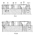
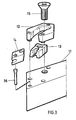
- Figs. 1, 2 and 3 show the working end of a turning tool 10 comprising a shank 11, a separate outer disc 12 provided to be secured to the shank and receiving an inner disc 13, an insert 14 and an adjusting screw 15.
- the upper face of the shank 11 which is mainly planar, is built up at the end with an outer disc 12 which is provided with three guiding pins at the lower face engaging in recesses in the upper face of the shank 11 with a press-fit.
- the guiding pins shall, in cooperation with some securing method, gluing or welding for example, secure the outer disc 12 to the shank 11.
- the outer disc 12 is loop-shaped and has two arms which mainly surround the inner disc 13.
- the inner disc 13 is received by a groove 16 in the disc 12 traversing the normal direction of said upper face and which is opened in the end of the outer disc 12 which is turned towards the working cutting tip.
- the groove 16 is terminated in its other end in an at least partly rounded-off spacing 17, which is provided to receive the adjusting screw 15.
- the outer disc 12 has support surfaces 18, 19 consisting of the walls of the groove 16 which are closest to the opening of the groove in direction towards the insert.
- the support surfaces 18, 19 diverge from each other such that the distance between their extension lines increases in direction from the insert toward the screw 15.
- the angle between the extension lines is between 10 to 30 ° .
- the support surfaces 20, 21 are parallel with the longitudinal axis A of the insert.
- the wall of the groove 16 is broken between the support surfaces 18 and 20 resp. 19 and 21.
- the inner disc 13 is displaceably arranged within the outer disc 12.
- the inner disc 13 is also loop-shaped.
- the ends of its arms partly enclose an acute-angled corner of the insert.
- the arms are resiliently arranged relative to each other by means of a slot 22.
- the inner disc 13 has support surfaces 23, 24, 25, 26 facing the support surfaces of the outer disc 12.
- the support surfaces 23-26 and the surfaces 18-21 have the same geometrical relationship to the longitudinal axis A of the insert.
- the inner parts of the ends of the arms carry rounded-off projections 27, 28.
- the insert 14 has a rhombical basic shape and comprises acute-angled and obtuse-angled corners, parallel flat surfaces connected by edge surfaces.
- the lines of intersection between flat surfaces and edge surfaces form cutting edges.
- the edge surfaces are provided with concave recesses 29, 30 and 31, 32, at least at the acute-angled comers.
- Each recess that can be V- or U-shaped, preferably the latter shape, has a larger radius than each projection 27, 28, seen in a plane normal to the upper face of the head portion.
- the insert 14 is provided with at least one hole 33, which extends perpendicularly to the lower flat surface.
- the hole 33 is arranged symmetrically around the longitudinal axis A and shaped such that a wide section 34 is arranged closer to the acute-angled corner than a narrower section 35.
- the hole 33 tapers continuously from the wider section 34 to the narrower section 35.
- the largest width of the wider section 34 is larger than the largest diameter of a positioning pin 36 while the smallest width of the narrower section 35 is less than the largest diameter of the positioning pin 36.
- the hole 33 is widened in the vicinity of the flat surfaces at the tapering portion and the narrower section 35.
- the insert is provided with two holes such that the insert may be indexed after it has been worn in one position.
- the non-cutting corner of the insert which is directed inwardly towards the adjusting screw 15, is passive in one position, in the sense of cutting. These corners interchange position at the indexing.
- the adjusting screw may alternatively be replaced by a powerful spring.
- the adjusting screw When the insert is to be mounted, the adjusting screw is unscrewed and the inner disc 13 is retracted.
- the insert 14 is positioned such that the positioning pin 36 enters into the wider section 34 of the hole 33, and such that the non-cutting, acute-angled comer of the insert is arranged between the projections 27, 28 of the inner disc 13.
- the adjusting screw 15 is screwed inwardly thereafter so that its conical head 15' abuts against complementary surfaces on the outer and inner discs.
- the inner disc 13 is thereby forced to move forwardly relative to the outer disc 12 at the same time as the arms of the inner disc 13 are forced in direction towards each other by the support surfaces 18, 19 of the outer disc 12, while the support surfaces 20, 21 on the outer disc guide the inner disc in a direction parallel with the longitudinal axis A.
- the projections 27, 28 abut the recesses 29, 30 in the edge surfaces of the insert, the insert is moved forwardly relative to the pin 36 until the width of the hole corresponds to the diameter of the pin, and therefore the insert is wedged up on the pin.
- the surfaces or points of the tapering portion of the hole 33, which cooperate with the pin, are arranged at a distance a from the center of the insert, which distance a is 0.5 to 1.5 times the radius R of a largest circle inscribed within the insert.
- a completely cylindrical pin can replace the above-mentioned pin 36.
- the pin is thus positioned in a boring which forms an acute angle z with the upper face of the shank.
- the advantage with this embodiment is that the wall of the insert hole can be completely perpendicular to the lower face of the insert and the insert becomes more simple to manufacture.
- the mounting of the insert is done in a manner corresponding to the one described above.
- Fig. 4 shows the tool in cross-section in the clamped position.
- the projections 27, 28 of the inner disc 13 abut against the lower parts of the recesses 29, 30 in the edge surfaces of the insert 14.
- the projections force the insert against the upper face of the tool shank through cooperation between the support surfaces 23, 24 of the inner disc 13 and the support surfaces of the outer disc 12.
- the support surfaces 18, 23 and 19, 24 converge in a direction from the upper face of the tool shank and form an angle a with each other.
- the angle a is suitably chosen within the interval 10 to 30 ° .
- the tool is arranged such that a small play arises between the lower face of each arm on the inner disc and the upper face of the shank.
- the resultant forces of the projections against the insert are illustrated by arrows in the figure. This illustrates how the insert is forced against the upper face of the shank.
- the points of abutment between the projections and the recesses are provided on opposite sides of the longitudinal axis of the insert.
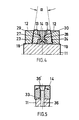
- Fig. 5 shows another cross-section through the tool in the clamped position.
- the pin 36 whose center line is perpendicular to the upper face of the shank 11, has a conical head 36', which cooperates with the upper portion of the hole 33.
- the upper portion is a termination of the hole and has a convexly increasing hole width in direction towards the flat surface of the insert.
- the head 36' of the pin presses the lower flat surface of the insert against the upper face of the shank.
- the points of abutment between the head and the hole are provided on opposite sides of the longitudinal axis of the insert.
- This embodiment has four active support points for the insert without being a statically over-determined clamping system, which is unique, two of which are arranged close to the cutting comer. The movement of the insert thereby becomes a minimum.
- the forces that arise during facing operations, see arrow F in Fig. 1, are effectively received by the pin 36.
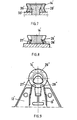
- FIGs. 6 - 8 show an alternative embodiment of a tool according to the invention.
- a round insert 14' is clamped to the tool shank 11'.
- the outer disc 12' encloses the inner disc 13' just as mentioned above.
- the arms of the inner disc 13' are forwardly terminated by the projections 27', 28'.
- a powerful spring 15" supports against the plane surface 17' and forces the inner disc 13' forwardly relative to the outer disc 12'.
- the projections thereby engage in the lower part of an annular recess 29 and force the insert forwardly and downwardly.
- the pin 36" comprises a conical abutment surface on both sides of the axis A, which abuts against a round hole 33' in the insert 14'.
- the largest width in a plane parallel with the upper face of the shank is less than the smallest diameter of the hole 33', such that the insert 14' easily can be loosened from the pin.
- the hole 33' is conically or convexly widened in the vicinity of the flat surfaces.
- the pin 36" and the hole 33 cooperate in order to force the insert against the bed.
- the surfaces or points of the hole 33', which cooperate with the pin, are arranged at a distance a' from the center of the insert which distance a' is 0.5 to 0.75 times the radius R' of a largest circle inscribed within the insert.
- FIG. 9 shows another alternative embodiment of a tool according to the invention.
- the edge surfaces of the insert 14" have recesses 29" separated from each other, each said recess has a spherically concave shape.
- the radius of the recess is larger than the radius of each of the spherically convex projections 27", 28" on the arms of the inner disc 13".
- inserts 14,14', 14" may also have alternative shapes within the scope of the subsequent claims.
- the inserts may have chip breakers of various kinds, such as recesses, grooves or projections.
- the present invention relates to a tool and an insert, wherein the insert and the clamping unit are shaped for safely securing the insert relative to the upper face of the shank.
Landscapes
- Engineering & Computer Science (AREA)
- Mechanical Engineering (AREA)
- Cutting Tools, Boring Holders, And Turrets (AREA)
- Workshop Equipment, Work Benches, Supports, Or Storage Means (AREA)
Claims (8)
Applications Claiming Priority (2)
| Application Number | Priority Date | Filing Date | Title |
|---|---|---|---|
| SE8502451A SE456652B (sv) | 1985-05-17 | 1985-05-17 | Verktyg och skaer foeretraedesvis foer svarvning |
| SE8502451 | 1985-05-17 |
Publications (3)
| Publication Number | Publication Date |
|---|---|
| EP0202209A2 EP0202209A2 (de) | 1986-11-20 |
| EP0202209A3 EP0202209A3 (en) | 1988-08-03 |
| EP0202209B1 true EP0202209B1 (de) | 1990-10-31 |
Family
ID=20360261
Family Applications (1)
| Application Number | Title | Priority Date | Filing Date |
|---|---|---|---|
| EP86850157A Expired - Lifetime EP0202209B1 (de) | 1985-05-17 | 1986-04-29 | Werkzeug und Einsatz, z.B. zum Drehen |
Country Status (5)
| Country | Link |
|---|---|
| US (1) | US4714384A (de) |
| EP (1) | EP0202209B1 (de) |
| JP (1) | JPS61265203A (de) |
| DE (1) | DE3675254D1 (de) |
| SE (1) | SE456652B (de) |
Families Citing this family (26)
| Publication number | Priority date | Publication date | Assignee | Title |
|---|---|---|---|---|
| CH679467A5 (de) * | 1989-06-29 | 1992-02-28 | Maag Zahnraeder & Maschinen Ag | |
| SE9101323D0 (sv) * | 1991-05-02 | 1991-05-02 | Mircona Ab | Anordning vid verktyg foer traanga utrymmen |
| FR2691657B1 (fr) * | 1992-05-26 | 1994-09-02 | M2P Mat Precision Production | Inserts autocentrants en polycristallin diamant ou nitrure de bore et autres matériaux de coupe, et leur dispositif de serrage et de centrage mécaniques. |
| KR950031336A (ko) * | 1994-02-28 | 1995-12-18 | 아키모토 유우미 | 드로우어웨이 팁 및 절삭공구 |
| SE505726C2 (sv) * | 1995-02-27 | 1997-10-06 | Sandvik Ab | Fastspänningsanordning för skärplattor |
| IL123685A (en) * | 1998-03-16 | 2001-09-13 | Iscar Ltd | Modular cutting tool dispenser |
| CN1125696C (zh) * | 1999-04-26 | 2003-10-29 | 桑德维克公司 | 刀夹和用于固定切削刀片的压板 |
| US6409435B1 (en) | 2000-07-03 | 2002-06-25 | Valenite Inc. | Cutting tool and method of locating cutting insert |
| SE522490C2 (sv) * | 2001-01-30 | 2004-02-10 | Sandvik Ab | Verktygshållare för skär för spånavskiljande bearbetning med flexibel sidoyta i skärläget |
| SE524560C2 (sv) * | 2001-01-30 | 2004-08-24 | Sandvik Ab | Verktygshållare med flexibelt fastspänningsorgan |
| SE521183C2 (sv) * | 2001-03-15 | 2003-10-07 | Sandvik Ab | Skärhållare med organ för justering av skärlägeshållaren |
| US6652200B2 (en) * | 2001-11-01 | 2003-11-25 | Rolf H. Kraemer | Tool holder with coolant system |
| DE10245906A1 (de) * | 2002-10-01 | 2004-04-15 | Sandvik Ab | Schneidplattenbefestigungssystem |
| DE202004008642U1 (de) * | 2004-05-27 | 2005-09-29 | Kennametal Inc. | Fräswerkzeug |
| DE102006025293C5 (de) * | 2006-05-31 | 2010-12-23 | Kennametal Inc. | Verfahren zur Bearbeitung eines Rades |
| CN101754828B (zh) * | 2007-06-06 | 2016-01-27 | 诺斯库有限公司 | 刀具架及其所用的刀头 |
| JP5028687B2 (ja) * | 2007-09-10 | 2012-09-19 | 住友電工ハードメタル株式会社 | 刃先交換式切削チップ |
| WO2010067369A2 (en) * | 2008-12-10 | 2010-06-17 | No Screw Ltd. | A cutting tool holder and a cutting insert therefor |
| DE112011100215T5 (de) * | 2010-01-07 | 2015-10-01 | Gkn Sinter Metals, Llc. | Bearbeitungswerkzeug und Verfahren zu dessen HerstellUng |
| US8727674B2 (en) * | 2012-02-16 | 2014-05-20 | Kennametal Inc. | Tool holder with nubs for clamping a cutting insert with notches |
| US9120154B2 (en) * | 2013-02-14 | 2015-09-01 | Iscar, Ltd. | Single-sided square-shaped indexable cutting insert and cutting tool |
| EP3096913B1 (de) * | 2014-01-22 | 2020-12-23 | Saturnino Fiori Cate S.r.l | Werkzeughaltevorrichtung für ein bearbeitungswerkzeug und verfahren zum verriegeln eines werkzeuges in einem werkzeughalter |
| CN109865852A (zh) * | 2019-03-14 | 2019-06-11 | 陈壮壮 | 一种硬质合金刀头 |
| US11612943B2 (en) * | 2019-08-01 | 2023-03-28 | Iscar, Ltd. | Insert adaptor and turning tool comprising same |
| US11701719B2 (en) * | 2019-12-26 | 2023-07-18 | Iscar, Ltd. | Cutting insert adaptor and tool assembly |
| JP2023006138A (ja) * | 2021-06-30 | 2023-01-18 | 三菱マテリアル株式会社 | 切削インサートのクランプ構造および刃先交換式切削工具 |
Family Cites Families (15)
| Publication number | Priority date | Publication date | Assignee | Title |
|---|---|---|---|---|
| US3220088A (en) * | 1961-12-13 | 1965-11-30 | Fagersta Bruks Ab | Turn cutter with concave base surfaces and a holder for such a cutter |
| DE1477396B2 (de) * | 1963-09-05 | 1971-04-01 | Hertel, Karl, 8500 Nürnberg | Schneidwerkzeug insbesondere zum drehen |
| DE1477243A1 (de) * | 1964-05-14 | 1969-10-16 | Deutsche Edelstahlwerke Ag | Wendeschneidplatte |
| SE334789B (de) * | 1967-12-22 | 1971-05-03 | Sandvikens Jernverks Ab | |
| US3551977A (en) * | 1969-04-08 | 1971-01-05 | Warner Swasey Co | Blade-like cutoff tool |
| DE2031832A1 (de) * | 1970-06-26 | 1971-12-30 | Heinlein H | Stechwerkzeug mit auswechselbaren Schneid- bzw. Wendeplatten |
| BE793254A (fr) * | 1971-12-23 | 1973-04-16 | Hertel Karl | Outil de coupe |
| US3821837A (en) * | 1972-07-07 | 1974-07-02 | Sandvik Ab | Cutting insert and cutting tool |
| FR2271894A1 (en) * | 1974-05-21 | 1975-12-19 | Ass Eng Ltd | Sintered polygonal cutter bit - mounted on holder with angular adjustment |
| SE405558B (sv) * | 1975-05-20 | 1978-12-18 | Seco Tools Ab | Skerhallare |
| FR2332090A1 (fr) * | 1975-11-21 | 1977-06-17 | Plansee Metallwerk | Porte-outil, notamment pour tours a copier |
| CA1074985A (en) * | 1978-05-05 | 1980-04-08 | J.P. Tool Limited | Machine tool cutter |
| AT361269B (de) * | 1978-09-28 | 1981-02-25 | Ver Edelstahlwerke Ag | Prismatischer schneideinsatz |
| DE3136549A1 (de) * | 1981-09-15 | 1983-03-31 | Feldmühle AG, 4000 Düsseldorf | Schneidwerkzeug |
| SE445314B (sv) * | 1984-09-26 | 1986-06-16 | Santrade Ltd | Verktyg med vendsker foretredesvis for svarvning |
-
1985
- 1985-05-17 SE SE8502451A patent/SE456652B/sv not_active IP Right Cessation
-
1986
- 1986-04-29 DE DE8686850157T patent/DE3675254D1/de not_active Expired - Lifetime
- 1986-04-29 EP EP86850157A patent/EP0202209B1/de not_active Expired - Lifetime
- 1986-05-16 US US06/863,934 patent/US4714384A/en not_active Expired - Fee Related
- 1986-05-16 JP JP61110958A patent/JPS61265203A/ja active Pending
Also Published As
| Publication number | Publication date |
|---|---|
| DE3675254D1 (de) | 1990-12-06 |
| SE8502451L (sv) | 1986-11-18 |
| SE456652B (sv) | 1988-10-24 |
| US4714384A (en) | 1987-12-22 |
| EP0202209A3 (en) | 1988-08-03 |
| JPS61265203A (ja) | 1986-11-25 |
| EP0202209A2 (de) | 1986-11-20 |
| SE8502451D0 (sv) | 1985-05-17 |
Similar Documents
| Publication | Publication Date | Title |
|---|---|---|
| EP0202209B1 (de) | Werkzeug und Einsatz, z.B. zum Drehen | |
| US4992007A (en) | Cutting insert and a tool holder therefor | |
| EP0010074B1 (de) | Schneidwerkzeug | |
| CA1104330A (en) | Clamping mechanism for cutting insert | |
| EP1159101B1 (de) | Werkzeughalter mit ersetzbarem einsatzträger | |
| EP0851796B1 (de) | Schneidewerkzeug mit wendeplattenspannvorrichtung | |
| CA2131779C (en) | Cutting tool | |
| US5333972A (en) | Special boring insert | |
| EP1013364B1 (de) | Schneidwerkzeugzusammenbau | |
| CA1243194A (en) | Cutting tool | |
| US3859700A (en) | Inserted blade cutter | |
| KR100359964B1 (ko) | 천공된삽입체를위한클램프를갖는공구홀더 | |
| JPH09108923A (ja) | 切削工具組立体 | |
| US4632606A (en) | Cutting tool and cutting insert | |
| US4035890A (en) | Toolholder | |
| US4669924A (en) | Insert retaining apparatus | |
| EP1569769B1 (de) | Schneideinsatz mit sternförmiger aussparung zur aufnahme der klemme | |
| EP0526438B1 (de) | Schneidwerkzeug | |
| US20050207853A1 (en) | Cutting tool head for a metalworking tool | |
| GB2081142A (en) | Profiling Insert and Holder | |
| US4583886A (en) | Cutting insert clamping assembly for cutting tool | |
| JPH0450121B2 (de) | ||
| EP0502834B1 (de) | Schneidwerkzeug für einer Schäloperation | |
| JPH11104904A (ja) | 溝入れ用バイトホルダおよびそのスローアウェイチップ | |
| SU1720804A1 (ru) | Режущий инструмент |
Legal Events
| Date | Code | Title | Description |
|---|---|---|---|
| PUAI | Public reference made under article 153(3) epc to a published international application that has entered the european phase |
Free format text: ORIGINAL CODE: 0009012 |
|
| AK | Designated contracting states |
Kind code of ref document: A2 Designated state(s): DE FR GB IT SE |
|
| PUAL | Search report despatched |
Free format text: ORIGINAL CODE: 0009013 |
|
| RHK1 | Main classification (correction) |
Ipc: B23B 27/16 |
|
| AK | Designated contracting states |
Kind code of ref document: A3 Designated state(s): DE FR GB IT SE |
|
| 17P | Request for examination filed |
Effective date: 19890125 |
|
| 17Q | First examination report despatched |
Effective date: 19890613 |
|
| GRAA | (expected) grant |
Free format text: ORIGINAL CODE: 0009210 |
|
| ITF | It: translation for a ep patent filed | ||
| AK | Designated contracting states |
Kind code of ref document: B1 Designated state(s): DE FR GB IT SE |
|
| REF | Corresponds to: |
Ref document number: 3675254 Country of ref document: DE Date of ref document: 19901206 |
|
| ET | Fr: translation filed | ||
| ITTA | It: last paid annual fee | ||
| PLBE | No opposition filed within time limit |
Free format text: ORIGINAL CODE: 0009261 |
|
| STAA | Information on the status of an ep patent application or granted ep patent |
Free format text: STATUS: NO OPPOSITION FILED WITHIN TIME LIMIT |
|
| 26N | No opposition filed | ||
| PGFP | Annual fee paid to national office [announced via postgrant information from national office to epo] |
Ref country code: FR Payment date: 19930408 Year of fee payment: 8 |
|
| PGFP | Annual fee paid to national office [announced via postgrant information from national office to epo] |
Ref country code: SE Payment date: 19930419 Year of fee payment: 8 Ref country code: GB Payment date: 19930419 Year of fee payment: 8 |
|
| PGFP | Annual fee paid to national office [announced via postgrant information from national office to epo] |
Ref country code: DE Payment date: 19930506 Year of fee payment: 8 |
|
| PG25 | Lapsed in a contracting state [announced via postgrant information from national office to epo] |
Ref country code: GB Effective date: 19940429 |
|
| PG25 | Lapsed in a contracting state [announced via postgrant information from national office to epo] |
Ref country code: SE Effective date: 19940430 |
|
| PG25 | Lapsed in a contracting state [announced via postgrant information from national office to epo] |
Ref country code: FR Effective date: 19941229 |
|
| PG25 | Lapsed in a contracting state [announced via postgrant information from national office to epo] |
Ref country code: DE Effective date: 19950103 |
|
| GBPC | Gb: european patent ceased through non-payment of renewal fee |
Effective date: 19940429 |
|
| EUG | Se: european patent has lapsed |
Ref document number: 86850157.8 Effective date: 19941110 |
|
| REG | Reference to a national code |
Ref country code: FR Ref legal event code: ST |
|
| PG25 | Lapsed in a contracting state [announced via postgrant information from national office to epo] |
Ref country code: IT Free format text: LAPSE BECAUSE OF NON-PAYMENT OF DUE FEES;WARNING: LAPSES OF ITALIAN PATENTS WITH EFFECTIVE DATE BEFORE 2007 MAY HAVE OCCURRED AT ANY TIME BEFORE 2007. THE CORRECT EFFECTIVE DATE MAY BE DIFFERENT FROM THE ONE RECORDED. Effective date: 20050429 |