EP0201673B1 - Vorrichtung zum automatischen Wechseln von Einwickelmaterial - Google Patents
Vorrichtung zum automatischen Wechseln von Einwickelmaterial Download PDFInfo
- Publication number
- EP0201673B1 EP0201673B1 EP19860102532 EP86102532A EP0201673B1 EP 0201673 B1 EP0201673 B1 EP 0201673B1 EP 19860102532 EP19860102532 EP 19860102532 EP 86102532 A EP86102532 A EP 86102532A EP 0201673 B1 EP0201673 B1 EP 0201673B1
- Authority
- EP
- European Patent Office
- Prior art keywords
- roller
- wrapping material
- change
- over
- knife
- Prior art date
- Legal status (The legal status is an assumption and is not a legal conclusion. Google has not performed a legal analysis and makes no representation as to the accuracy of the status listed.)
- Expired - Lifetime
Links
Images



Classifications
-
- B—PERFORMING OPERATIONS; TRANSPORTING
- B65—CONVEYING; PACKING; STORING; HANDLING THIN OR FILAMENTARY MATERIAL
- B65H—HANDLING THIN OR FILAMENTARY MATERIAL, e.g. SHEETS, WEBS, CABLES
- B65H19/00—Changing the web roll
- B65H19/10—Changing the web roll in unwinding mechanisms or in connection with unwinding operations
- B65H19/18—Attaching, e.g. pasting, the replacement web to the expiring web
- B65H19/1857—Support arrangement of web rolls
- B65H19/1873—Support arrangement of web rolls with two stationary roll supports carrying alternately the replacement and the expiring roll
-
- B—PERFORMING OPERATIONS; TRANSPORTING
- B65—CONVEYING; PACKING; STORING; HANDLING THIN OR FILAMENTARY MATERIAL
- B65H—HANDLING THIN OR FILAMENTARY MATERIAL, e.g. SHEETS, WEBS, CABLES
- B65H19/00—Changing the web roll
- B65H19/10—Changing the web roll in unwinding mechanisms or in connection with unwinding operations
- B65H19/105—Opening of web rolls; Removing damaged outer layers; Detecting the leading end of a closed web roll
-
- B—PERFORMING OPERATIONS; TRANSPORTING
- B65—CONVEYING; PACKING; STORING; HANDLING THIN OR FILAMENTARY MATERIAL
- B65H—HANDLING THIN OR FILAMENTARY MATERIAL, e.g. SHEETS, WEBS, CABLES
- B65H19/00—Changing the web roll
- B65H19/10—Changing the web roll in unwinding mechanisms or in connection with unwinding operations
- B65H19/18—Attaching, e.g. pasting, the replacement web to the expiring web
- B65H19/1805—Flying splicing, i.e. the expiring web moving during splicing contact
- B65H19/1826—Flying splicing, i.e. the expiring web moving during splicing contact taking place at a distance from the replacement roll
- B65H19/1836—Flying splicing, i.e. the expiring web moving during splicing contact taking place at a distance from the replacement roll the replacement web being accelerated or running prior to splicing contact
-
- Y—GENERAL TAGGING OF NEW TECHNOLOGICAL DEVELOPMENTS; GENERAL TAGGING OF CROSS-SECTIONAL TECHNOLOGIES SPANNING OVER SEVERAL SECTIONS OF THE IPC; TECHNICAL SUBJECTS COVERED BY FORMER USPC CROSS-REFERENCE ART COLLECTIONS [XRACs] AND DIGESTS
- Y10—TECHNICAL SUBJECTS COVERED BY FORMER USPC
- Y10T—TECHNICAL SUBJECTS COVERED BY FORMER US CLASSIFICATION
- Y10T83/00—Cutting
- Y10T83/141—With means to monitor and control operation [e.g., self-regulating means]
- Y10T83/148—Including means to correct the sensed operation
-
- Y—GENERAL TAGGING OF NEW TECHNOLOGICAL DEVELOPMENTS; GENERAL TAGGING OF CROSS-SECTIONAL TECHNOLOGIES SPANNING OVER SEVERAL SECTIONS OF THE IPC; TECHNICAL SUBJECTS COVERED BY FORMER USPC CROSS-REFERENCE ART COLLECTIONS [XRACs] AND DIGESTS
- Y10—TECHNICAL SUBJECTS COVERED BY FORMER USPC
- Y10T—TECHNICAL SUBJECTS COVERED BY FORMER US CLASSIFICATION
- Y10T83/00—Cutting
- Y10T83/465—Cutting motion of tool has component in direction of moving work
- Y10T83/4708—With means to render cutter pass[es] ineffective
-
- Y—GENERAL TAGGING OF NEW TECHNOLOGICAL DEVELOPMENTS; GENERAL TAGGING OF CROSS-SECTIONAL TECHNOLOGIES SPANNING OVER SEVERAL SECTIONS OF THE IPC; TECHNICAL SUBJECTS COVERED BY FORMER USPC CROSS-REFERENCE ART COLLECTIONS [XRACs] AND DIGESTS
- Y10—TECHNICAL SUBJECTS COVERED BY FORMER USPC
- Y10T—TECHNICAL SUBJECTS COVERED BY FORMER US CLASSIFICATION
- Y10T83/00—Cutting
- Y10T83/889—Tool with either work holder or means to hold work supply
- Y10T83/896—Rotatable wound package supply
- Y10T83/902—Plural supply sources
Definitions
- the present invention relates to an automatic wrapping material change-over apparatus and more particularly to an apparatus for changing over from a wrapping material being delivered from one bobbin to a wrapping material on the other bobbin in a wrapping material feeding system which draws out a wrapping material from a bobbin on which the wrapping material is wound, then cuts it into a predetermined size and then transfers it to a wrapping machine.
- the change-over knife performs its cutting operation in conformity with the timing of a knife of the wrapping material feeding system.
- wrapping materials having different cut sizes are sent to the wrapping machine at the time of the change-over.
- a conventional cutter knife is constructed so that at the time of cutting operation a knife roller rotates to a knife receiving roller side to cut a material moving therebetween. In this case, there occurs a slight time lag during rotation of the knife roller, so when such a change-over knife is applied to the above change-over apparatus, it is difficult to take timing with the knife of the wrapping material feed system.
- DE-A 2 717 631 describes an apparatus for a butt joining of paper webs by placing an adhesive tape on the butt joined ends of said webs.
- the first paper web which is wound around a first upper working reel is out of stock
- the second paper web is paid out manually from the second lower reel onto a collecting roller to be joined to the preceding first web by first cutting the overlapping trailing and leading end portions of respective webs.
- a piece of an adhesive tape is placed on an application roller and is applied on the butt joined ends of said webs.
- the inventive apparatus is advantageously also applicable to a wrapping material feed system, which cuts a wrapping material with pattern into a predetermined size while registering the pattern and then supplies the cut material to a wrapping machine. Furthermore, the inventive apparatus is advantageously provided with a cutting device capable of easily taking timing within another member.
- Figs. 1 to 7 illustrate a first embodiment of the present invention, of which:
- Fig. 1 is a schematic illustration of the whole of a wrapping material feed system equipped with an automatic wrapping material change-over apparatus according to the present invention
- Fig. 2 illustrates a power transfer route thereof.
- the reference numerals 1 and 101 denote bobbins and the numerals 2 and 102 denote wrapping materials with patterns thereon.
- the wrapping materials 2 and 102 are given a delivery force by a feed roller 3 and a receiving roller 4 to be drawn out from the bobbins 1 and 101, then are guided to an automatic change-over apparatus embodying the invention by means of direction changing feed rollers 5, 105 and receiving rollers 6, 106, and after passing the change-over apparatus, those wrapping materials are cut into a predetermined size by a main knife roller 7 and a knife receiving roller 8, then pasted and conveyed to a wrapping step.
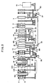
- the automatic change-over apparatus of the present invention is composed of a first take-up roller device for taking up the wrapping material from the bobbin 1 (the first take-up roller device comprising a change-over feed roller 9, a receiving roller 10, a collection roller 11, a suction separation roller 14 and a take-up roller 15), a second take-up roller device for taking up the wrapping material from the bobbin 101 (the second take-up roller device comprising a change-over feed roller 109, a receiving roller 110, a collection roller 111, a suction separation roller 114 and a take-up roller 115), a drive device for driving the second-take-up roller device (the drive device comprising a motor 16, an electromagnetic clutch 17 and a differential gear 18), and a change-over knife device for cutting the wrapping materials 2 and 102 (the change-over knife device comprising a change-over knife roller 12 and a change-over knife receiving roller 13).
- the first take-up roller device comprising a change-over feed roller 9, a receiving roller 10, a
- the change-over feed rollers 9, 109, receiving rollers 10,110, collection rollers 11, 111, change-over knife roller12, change-over knife receiving roller 13 and suction separation rollers 14, 114, which constitute the first and second take-up roller devices and the change-over knife device, are disposed along a Y-shaped passage.
- FIG. 3 there is fully illustrated the automatic change-over apparatus of the present invention in which on an inlet side (upper position in Fig. 3) of the Y-shaped passage there are disposed register mark detectors 20 and 120 for detecting patterns affixed at predetermined intervals to the wrapping materials 2 and 102, as well as suction brakes 21 and 121, while in positions close to the take-up rollers 15 and 115 there are disposed air cylinders 22 and 122 for discharging front end portions of the wrapping materials 2 and 102.
- register mark detectors 20 and 120 for detecting patterns affixed at predetermined intervals to the wrapping materials 2 and 102, as well as suction brakes 21 and 121, while in positions close to the take-up rollers 15 and 115 there are disposed air cylinders 22 and 122 for discharging front end portions of the wrapping materials 2 and 102.
- the air cylinders 22 and 122 have discharge portions 22a and 122a provided at fore ends of the respective pistons, the discharge portions 22a and 122a being adapted to move along the peripheral surfaces of the take-up rollers 15 and 115 (axially of the rollers 15 and 115) to discharge the wound-up wrapping materials 2 and 102 from the peripheral surfaces of the take-up rollers 15 and 115, as shown in Fig. 2.
- take-up confirmation detectors 23 and 123 there are disposed take-up confirmation detectors 23 and 123, respectively.
- a guide 25 which is moved up and down by a cylinder 24. The guide 25 moves down during preparation for change-over to permit the wrapping materials 2 and 102 to move toward the take-up rollers 15 and 115.
- the motor 16 as a constituent of the drive device causes the first take-up roller device (change-over feed roller 9, collection roller 11, suction separation roller 14 and take-up roller 15) or the second take-up roller device (change-over feed roller 109, collection roller 111, suction separation roller 114 and take-up roller 115) to rotate at a low speed.
- the electromagnetic clutch 17 transfers the rotation of a main motor 19 (see Fig. 2) to the first take-up roller device (change-over feed roller 9, collection roller 11, suction separation roller 14 and take-up roller 15) or to the second take-up roller device (change-over feed roller 109, collection roller 111, suction separation roller 114 and take-up roller 115).
- This harmonic differential unit is composed of a wave generator (comprising an elliptic cam and a ball bearing fitted over the outer periphery thereof), a flex-spline (a thin-walled cup-like metallic elastic body having an opening portion with involute teeth formed on the outer periphery thereof) and a circular spline ( a ring-like rigid body provided on the inner periphery thereof with teeth of the same pitch as the flex-spline, the number of the teeth being larger by two than the teeth of the flex-spline).
- a wave generator comprising an elliptic cam and a ball bearing fitted over the outer periphery thereof
- a flex-spline a thin-walled cup-like metallic elastic body having an opening portion with involute teeth formed on the outer periphery thereof
- a circular spline a ring-like rigid body provided on the inner periphery thereof with teeth of the same pitch as the flex-spline, the number of the teeth being larger
- the differential gear18 increases or decreases the revolution of the change-over feed roller 9 or 109 without increasing the revolution of the motor 19 for registering pattern at the time of change-over operation through of a stepping motor 26 (see Fig. 2, the stepping motor 26 being controlled with signals provided from the register mark detectors 20 and 120) which is an adjusting motor for the differential gear.
- a differential gear 37 on the side of the wrapping material feed system is also constituted by a harmonic differential unit, and by a stepping motor 38 see Fig. 2, the stepping motor 38 being controlled with a signal provided from a register mark detector 31) which is an adjusting motor for the differential gear, the revolution of the feed roller 3 is increased or decreased without increasing or decreasing the revolution of the motor 19 for registering pattern during delivery of the wrapping materials.
- the rotational shaft of the change-over knife receiving roller 13 as a constituent of the change-over knife device is eccentric and a short-diameter side thereof is normally opposed to the change-over knife roller 12.
- an SR clutch as shown in Fig. 2.
- the SR clutch 28 is composed of an outer race 28a (connected to the drive system of the motor 16 on the drive side), an inner race 28b (connected to the change-over knife receiving roller 13 on the load side) and a roller 28c interposed between the outer and inner races 28a and 28b, as shown in fig. 4.
- the roller 28c is held within a trip came cage 28d and it is located in its solid line position (ON) in the same figure under the action of a coil spring 28e.
- a step portion 28f of the trip cam cage 28d is pushed in the direction of arrow in Fig. 4 by a lever 27 (see Figs. 2 and 4)
- the roller 28c assumes the position (OFF) indicated by an alternative long and two short dashes line in the same figure.
- the change-over knife roller 12 is normally rotated by the motor 19.
- the reference numerals 32 and 132 denote fore-end strippers; numerals 33 and 133 denotes preliminary suction rollers; numerals 34 and 134 denote tension rollers; numerals 35 and 135 denote preliminary feed rollers; and numeral 36 denotes a motor.
- the rollers 9, 109, 10, 110, 11 and 111 of the automatic change-over device are all retreated and so gaps are formed between rollers.
- the wrapping material 2 is given a delivery force by the feed roller 3 driven by the motor 19 and the receiving roller 4 and it passes the preliminary suction roller 33, tension roller 34 and preliminary feed roller 35, then is changed its direction by the direction changed feed roller 5 and thereafter passes the automatic change-over apparatus.
- a one-way clutch is incorporated in each of the direction changing feed roller 5 (105) and collection roller 11 (111) to reduce the delivery resistance.
- the register mark detector 31 Whether or not there is feed lag of the wrapping material 2 is detected by the register mark detector 31 while the wrapping material passes the automatic change-over apparatus.
- the stepping motor 38 operates in accordance with a signal provided from the detector 31 such that the revolution of the feed roller 3 is increased or decreased by the differential gear 37 without increasing or decreasing the revolution of the motor 19, to correct the feed lag.
- the wrapping material 2 is cut into predetermined size and pattern by the main knife roller 7 and knife receiving roller 8, then pasted by a paste roller 50 and a receiving roller 51 and thereafter sent to a wrapping machine.
- the fore-end stripper 132 is pushed against the wrapping material 102 on the bobbin 101. Then, the bobbin 101 is rotated slowly by the motor 36. When a fore end portion of the wrapping material 102 is detected by a sensor (not shown) attached to the fore-end stripper 132, the rotation of the bobbin 101 stops. Then, a bobbin brake (not shown) turns ON and a fore end nipper (not shown) of the fore-end stripper 132 closes to nip the fore end portion of the wrapping material 2. The fore-end stripper 132 is then forced down while nipping the fore end portion of the wrapping material 2 and goes away from the bobbin 101.
- the preliminary suction roller 133 operates to such the fore end portion of the wrapping material 102.
- the fore end nipper of the fore-end stripper 132 opens and releases the fore end portion of the wrapping material 102:
- the tension roller 134 is forced down and the fore end portion of the wrapping material 102 is pushed against the preliminary suction roller 133 by means of a fore-end pressing spring (not shown).
- the bobbin brake is turned OFF and the bobbin 101 is rotated slowly by a motor 36.
- the suction of the suction separation roller 114 and take-up roller 115 becomes ON and then the receiving roller 106 is released from its retreated state. Thereafter, the second take-up roller device (change-over feed roller 109, collection roller 111, suction separation roller 114 and take-up roller 115) is rotated slowly by the motor 16.
- the release of the retreated state of the solenoid 139 is effected by turning the solenoid 139 (see Fig. 2) from ON to OFF.
- the rotation of the motor 36 is stopped, the tension roller 134 is pushed up and the guide 25 is brought down by the cylinder 24.
- the take-up confirmation detector 123 that the take-up roller 115 has taken up the fore end portion of the wrapping material 102 and when pattern is detected by the register mark detector 120, the motor 16 stops rotation.
- the suction brake 121 turns ON, the suction of the suction separation roller 114 turns OFF and the guide 25 is moved up by the cylinder 24.
- the electromagnetic clutch 17 is turned ON to transfer the rotation of the motor19 of the wrapping material feed system to the second take-up roller device to drive the latter at a constant speed, namely, at a speed ratio thereof to the wrapping material feed system of 1 : 1. Then, upon detection of pattern by the register mark detector 120, there is made registering of pattern between the wrapping materials 102 and 2.
- the registering of pattern is performed in accordance with the pattern registering routine shown in Fig. 7.
- a mechanical angle of the wrapping material feed system is detected by a rotary encoder 40 and an angle read port of a microcomputer (not shown) is latched upon detection of a register mark.
- lag of pattern advance is calculated from the latched angle and the number of pulse for correction the said lag is determined. This number of pulse is provided to the stepping motor 26 in accordance with an up-down system to drive the motor.
- a lead pulse is provided, while when the latched angle is in the range of 180° to 359 ° , a lag pulse is provided, whereby the differential gear 18 is operated to increase or decrease the revolution of the change-over feed roller 109.
- the register mark of the wrapping material 102 coincides with that of the wrapping material 2.
- an edge position of the change-over knife roller 12 is detected by a photo switch 41 and the SR clutch 28 is turned ON by the solenoid 29, whereupon the change-over knife receiving roller 13 rotates and pushes the wrapping materials 102 and 2 against the change-over knife roller 12 to cut the wrapping materials 102 and 2 at a time to produce a free wrapping material cut off from the wrapping material 2 and a discard leading portion from the wrapping material 102.
- the SR clutch 28 is then turned OFF by the solenoid 30.
- the revolution of the main feed roller 3 is increased by the differential gear 37 to advance the wrapping material 2 so that a gap of about 0.8 mm is formed between the rear end of the wrapping material 2 and the fore end of the wrapping material 2 and the fore end of the wrapping material 102 and the main knife roller 7 acts in the gap between the the cut ends.
- the main knife roller 7 and the change-over knife roller 12 are normally rotated by the motor 19 always under the same timing. During the change-over operation, therefore, the wrapping materials 2 and 102 can be cut by the change-over knife roller 12 at the same timing as the main knife roller 7.
- the wrapping material 102 is held under tension while moving at the same speed as the wrapping material 2, so there is no fear of an error (such as feed lag) caused by loosening of the wrapping material 102.
- the change-over knife receiving roller 13 is an eccentric roller and it is rotated by the SR clutch 28, it can be stopped positively with its short diameter side opposed to the change-over knife roller12. Moreover, since the half of the change-over knife receiving roller 13 is a large diameter section 25a, the cutting can be done during 180 ° rotation of the roller 13 and consequently it is possible to take margin for adjustment of the change-over timing.
- the guide 25 is brought down to create a large gap between the guide 25 and the suction separation roller 114 (14), so it becomes easier for the wrapping material 10 (2) to be delivered toward the take-up roller 115 (15). Besides, during the change-over operation the guide 25 is moved up to minimize the gap, so it is not possible that the fore end of the wrapping material 102 (2) which has been cut by the change-over knife roller 12 will be engaged with the suction separation roller 114 (14).
- FIGs. 8 and 9 there is illustrated a second embodiment of the present invention, in which the change-over preparing operation is performed manually and not automatically as in the above embodiment.
- the same constructional portions as in Figs. 1 to 3 are indicated by the same reference numerals and explanations on their details will be omitted.
- an electromagnetic single position clutch 44 is provided in addition to an electromagnetic clutch 17.
- the clutch 17 is turned ON, the rotation of the motor 19 is transferred to a first take-up roller device (change-over feed roller 9, guide roller 43, take-up roller 15) or a second take-up roller device (change-over feed roller 109, guide roller 143, take-up roller 115), where the first or second take-up roller device begins to rotate as a speed ratio thereof to the wrapping material feed system of 1 : 0.957.
- the electromagnetic single position clutch 44 is energized.
- the clutch 44 is composed of a magnet body portion 44a (which incorporates therein a coil 44d) having teeth 44c formed on a side face thereof and an armature portion 44b having teeth 44e adapted to engage the teeth 44c.
- a magnet body portion 44a which incorporates therein a coil 44d
- armature portion 44b having teeth 44e adapted to engage the teeth 44c.
- the foregoing speed ratio changes from 1 : 0.957 to 1 : 1. This is for the following reason.
- the first or second take-up roller device which is off cannot immediately operate at a speed ratio of 1 1 at the same timing as the wrapping material feed system, that is, there occurs a slight delay, so the electromagnetic single position clutch 44 is used to take a complete timing and the electromagnetic clutch 17 is used for auxiliary rotation.
- slits for register of mark are formed in flanges 45 and 145 (see Fig. 8) of the change-over feed rollers 9 and 109. If the wrapping materials 2 and 102 are wound onto the take-up rollers 15 and 115 while conforming marks to those slits, the cutting portion at the change-over knife rollers 12 and 112 will become coincident with that at the main knife roller 7.
- the wrapping material 2 In normal condition, for example where the wrapping material 2 is drawn out from the bobbin 1, it is given a delivery force by a feed roller 3 and a receiving roller 4. With this delivery force, the wrapping material 2 passes a guide roller 46, tension roller 47, guide rollers 48, 49, then passes the first take-up roller device and reaches a register mark detector 31, and possible feed lag of the wrapping material 2 having register mark is detected by the register mark detector 31. In the event the lag of register mark is detected, the revolution of the feed roller 3 is increased or decreased by a differential gear 37 to correct the mark shear. Thereafter, the wrapping material 2 is cut into predetermined size and pattern by means of a main knife roller 7 and a knife receiving roller 8, then pasted by a paste roller 50 and a receiving roller 51 and thereafter sent to a wrapping machine.
- the discard leading end of the wrapping material 102 on the bobbin 101 is drawn out manually and is passed around a guide roller 146, tension roller 147 and guide roller 149. Then, it is passed between the change-over feed roller 109 -and the receiving roller 110, between the change-over knife roller 112 and the change-over knife receiving roller 113 and further between the guide rollers 43 and 143, and is wound onto a take-up roller 115 (set to the second take-up roller device). At this time, the fore end of the register mark of the wrapping material 102 is conformed to the slit of the flange 145.
- the above change-over preparing operation is performed manually, but the following switching operation is conducted automatically like the previous embodiment.
- the electromagnetic clutch 17 turns ON when the residual volume of the wrapping material 2 becomes small, and the second take-up roller device begins to rotate at a speed ratio thereof to the wrapping material feed system of 1 : 0.957, which speed ratio changes to 1 : 1 upon turning ON of the electromagnetic single position clutch 44.
- whether the change-over knife rollers 12 and 112 are in positions capable of being switched over or not is detected by a photo switch 41.
- the SR clutch 28 operates and the change-over knife receiving rollers 13 and 113 rotate at a time to push the wrapping materials 2 and 102 against the change-over knife rollers 12 and 112 to cut them simultaneously.
- the bobbin 1 is stopped by a bobbin brake. And when the portion (rear end) of the wrapping material 2 cut by the change-over knife roller 12 approaches the main knife roller 7, the revolution of the main feed roller 3 is increased by the differential gear 37 to advance the wrapping material 2 thereby creating a gap of about 0.8 mm between the rear end of the wrapping material 2 and the fore end of the wrapping material 102.
- SR clutch 28 clutch mechanism
- Fig. 12b is a partial perspective view of a trip cam cage which constitutes the clutch mechanism;
- Fig. 12c is an explanatory view showing a relation between the trip cam cage and a lever.
- This change-over knife comprises change-over knife rollers 12, 112 and change-over knife receiving rollers 13, 113, which are disposed between change-over feed roller 9, receiving roller 10 and guide roller 43 and between chage-over feed roller 109, receiving roller 110 and guide roller 143.
- Figs. 11a and b show in detail the change-over knife roller 12 and the change-over knife receiving roller 13.
- the change-over knife roller 12 is rotated by the main motor 19 at the time of change-over.
- the change-over knife receiving roller 13 has an eccentric shaft (constituting an eccentric roller) and it is divided into a long-diameter portion 13a and a short-diameter portion 13b.
- SR clutch 28 is connected to the change-over knife receiving roller 13.
- the SR clutch 28 is composed of an outer race 26 (connected to the main motor 19 through engagement of teeth 34 and 35 shown in Fig. 11 b on the drive side), an inner race 27 (connected to a rotational shaft 13b of the change-over knife receiving roller 13 shown in Fig. 11 b on the load side) and a roller 29 disposed between the outer and inner races 26 and 27.
- the SR clutch 28 is normally kept off by engagement of the lever 31 with the step portion 30a under the action of a coil spring 36, and it turns ON when the solenoid 32 operates and the lever 31 is thereby disengaged from the step portion 30a, so that the outer and inner races 26 and 27 come into engagement with each other to transfer the rotation of the main motor 19 to the change-over knife receiving roller 13.
- both races turn fully once in this state, that is, when they return to their original positions, the lever 31 is brought into engagement with the step portion 30a by the coil spring 36 to turn off the clutch.
- Slits (not shown for register of pattern are formed in the flanges 45 and 145 (see Fig. 9) of the change-over feed rollers 9 and 109. If the wrapping materials 2 and 102 are wound up onto the take-up rollers 15 and 115 while conforming register marks to those slits, the cut portion at the change-over knife rollers 12 and 112 will come to coincide with the cut portion at the main knife roller 7.
- the cutting device of the above construction was applied to the automatic wrapping material change-over apparatus in the wrapping material feed system, this does not constitute any limitation, that is, the cutting device is applicable widely to any case where it is required to perform a cutting operation while taking timing with another member.
- the automatic wrapping material change-over apparatus includes take-up roller devices (first and second take-up roller devices) for taking up a wrapping material from another bobbin and rotating the latter during change-over operation, and a change-over knife device for simultaneously cutting the wrapping material from the another bobbin and that from one bobbin which are being moved and drawn out respectively by the take-up roller devices, in which the thus-cut end of the wrapping material from the another bobbin follows the thus-cut end of the wrapping material from the one bobbin both at the same speed. Because of such a construction there is no fear of timing error during the change-over operation.
- the automatic wrapping material change-over apparatus includes take-up roller devices (first and second take-up roller devices) for taking up a wrapping material from another bobbin and rotating the latter during change-over operation, a mark detector (register mark detector 20) for detecting a mark affixed to the wrapping material on one bobbin, a mark detector (register mark detector 120) for detecting a mark affixed to the wrapping material on the another bobbin, and a change-over knife device for simultaneously cutting the wrapping material from the another bobbin and that from the one bobbin which are being moved and drawn out respectively by the take-up roller devices upon detection of a register of marks between the wrapping materials from the one and the another bobbin, in which the thus-cut end of the wrapping material from the another bobbin follows the thus-cut end of the wrapping material from the one bobbin.
- take-up roller devices first and second take-up roller devices
- the knife receiving roller is made eccentric and between it and its drive mechanism (main motor 19) there is disposed a clutch mechanism (SR clutch 28) which connects the knife receiving roller to the drive mechanism so that the large diameter section of the knife receiving roller rotates to the knife roller side at the time of cutting operation and which cuts off the connection of the two so that the knife receiving roller stops rotation in a predetermined constant position at the end of the cutting operation. Therefore, at the start of cutting the knife receiving roller rotates always from the predetermined constant position, and there is a margin for adjustment of the cutting timing because about half of the knife receiving roller constitutes the large diameter section. Consequently, it is possible to effect the cutting operation easily while taking timing with another member.
- SR clutch 28 which connects the knife receiving roller to the drive mechanism so that the large diameter section of the knife receiving roller rotates to the knife roller side at the time of cutting operation and which cuts off the connection of the two so that the knife receiving roller stops rotation in a predetermined constant position at the end of the cutting operation. Therefore, at the start of cutting the knife receiving roller rotates always from
Landscapes
- Advancing Webs (AREA)
Claims (12)
Applications Claiming Priority (4)
| Application Number | Priority Date | Filing Date | Title |
|---|---|---|---|
| JP63229/85 | 1985-03-29 | ||
| JP4513585U JPH018317Y2 (de) | 1985-03-29 | 1985-03-29 | |
| JP45135/85 | 1985-03-29 | ||
| JP6322985A JPS61226443A (ja) | 1985-03-29 | 1985-03-29 | 包装部材の自動切換装置 |
Publications (3)
| Publication Number | Publication Date |
|---|---|
| EP0201673A2 EP0201673A2 (de) | 1986-11-20 |
| EP0201673A3 EP0201673A3 (en) | 1988-02-17 |
| EP0201673B1 true EP0201673B1 (de) | 1990-05-09 |
Family
ID=26385092
Family Applications (1)
| Application Number | Title | Priority Date | Filing Date |
|---|---|---|---|
| EP19860102532 Expired - Lifetime EP0201673B1 (de) | 1985-03-29 | 1986-02-27 | Vorrichtung zum automatischen Wechseln von Einwickelmaterial |
Country Status (3)
| Country | Link |
|---|---|
| US (1) | US4705225A (de) |
| EP (1) | EP0201673B1 (de) |
| DE (1) | DE3670999D1 (de) |
Families Citing this family (4)
| Publication number | Priority date | Publication date | Assignee | Title |
|---|---|---|---|---|
| US5797305A (en) * | 1996-02-12 | 1998-08-25 | Moore Business Forms, Inc. | On demand cross web perforation |
| FR2823190B1 (fr) * | 2001-04-10 | 2003-09-05 | Cermex Ouest Conditionnement | Procede pour recharger une fardeleuse a l'aide d'un film plastique, et fardeleuse mettant en oeuvre le procede |
| CN111300522A (zh) * | 2020-04-13 | 2020-06-19 | 广东川田卫生用品有限公司 | 一种用于卫生巾包膜生产线的换料裁切装置 |
| JP2025119380A (ja) * | 2024-02-01 | 2025-08-14 | 株式会社イシダ | 製袋包装装置 |
Family Cites Families (12)
| Publication number | Priority date | Publication date | Assignee | Title |
|---|---|---|---|---|
| US3089661A (en) * | 1961-06-14 | 1963-05-14 | American Mach & Foundry | Automatic cigarette paper splicer |
| DE1190286B (de) * | 1961-08-11 | 1965-04-01 | Huck Entwicklungs G M B H | Einrichtung zum registergleichen Verbinden einer vorbedruckten, ablaufenden Bahn mit einer vorbedruckten Ersatzrolle |
| US3925131A (en) * | 1971-05-14 | 1975-12-09 | Hauni Werke Koerber & Co Kg | Method of uniting webs of cigarette paper or the like |
| IT997143B (it) * | 1973-09-21 | 1975-12-30 | Seragnoli Ariosto | Apparecchiatura per produrre da materiale in nastro avvolto in bobina una successione continua di tratti di nastro o fogli partico larmente adatta per alimentare spezzoni di materiale d incarto a macchine incartatrici |
| IT1060326B (it) * | 1976-04-27 | 1982-07-10 | Carle E Montanari Spa | Dispositivo per assicurare la continuita del materiale d incarto in bobina alle macchine confezionatrici |
| DE2623804C3 (de) * | 1976-05-28 | 1981-08-20 | Jagenberg-Werke AG, 4000 Düsseldorf | Synchronisiereinrichtung für die Geschwindigkeiten zweier Warenbahnen |
| US4159661A (en) * | 1977-07-05 | 1979-07-03 | Egan Machinery Company | Rotary cutter |
| IT1166077B (it) * | 1979-04-03 | 1987-04-29 | Carle E Montanari Spa | Dispositivo giuntatore particolarmente adatto per assicurare la continuita del materiale d incarto alle macchine confezionatrici |
| US4346853A (en) * | 1979-08-29 | 1982-08-31 | Romano Stefanoni | Unwinding machine |
| US4361260A (en) * | 1980-06-27 | 1982-11-30 | Hanlan Marc A | Web registration control |
| IT1133400B (it) * | 1980-12-22 | 1986-07-09 | Gd Spa | Metodo e dispositivo per la sostituzione di una prima bobina di materiale in nastro di esaurimento con una seconda bobina nuova |
| IT1145778B (it) * | 1981-06-03 | 1986-11-12 | Gd Spa | Dispositivo di alimentazione e taglio in spezzoni un nastro continuo con cambio automatico della bobina di svolgimento del nastro |
-
1986
- 1986-02-26 US US06/833,581 patent/US4705225A/en not_active Expired - Lifetime
- 1986-02-27 DE DE8686102532T patent/DE3670999D1/de not_active Expired - Fee Related
- 1986-02-27 EP EP19860102532 patent/EP0201673B1/de not_active Expired - Lifetime
Also Published As
| Publication number | Publication date |
|---|---|
| DE3670999D1 (de) | 1990-06-13 |
| EP0201673A3 (en) | 1988-02-17 |
| US4705225A (en) | 1987-11-10 |
| EP0201673A2 (de) | 1986-11-20 |
Similar Documents
| Publication | Publication Date | Title |
|---|---|---|
| US4315794A (en) | Device for the quick splicing of paper webs | |
| US4532750A (en) | Winding body for winding-up continuously arriving flat structures, especially printed products in an imbricated product formation | |
| CA1257241A (en) | Process and apparatus for changing reels in connection with packaging machines | |
| FI116973B (fi) | Uudelleenrullauskone ja menetelmä rullien muodostamiseksi rainamateriaalista, käsittäen rainamateriaalin katkaisulaitteen | |
| US5116038A (en) | Paper feeding apparatus | |
| NL8203789A (nl) | Inrichting voor het opzamelen van in een schubformatie ter beschikking komende vlakke voortbrengselen, in het bijzonder drukprodukten. | |
| JP2923083B2 (ja) | 製造機械におけるストリップ材料の交換方法 | |
| EP0812664B1 (de) | Vorrichtung und Verfahren zum Perforieren von durchlaufendem Material und Vorrichtung und Verfahren zum Bearbeiten und Befestigen von photographischem Filmmaterial | |
| US4387614A (en) | Automated web chop-out control for cut-to-mark cut-off machine | |
| GB2090582A (en) | Perforating then cutting webs during splicing | |
| EP0201673B1 (de) | Vorrichtung zum automatischen Wechseln von Einwickelmaterial | |
| US5297751A (en) | Method of replacing strip material on a manufacturing machine | |
| US6578788B2 (en) | Accumulator and dispensing system for a cutting tape | |
| EP0166884A1 (de) | Verfahren und Vorrichtung zum Verbinden aufeinanderfolgender Papierbahnrollen | |
| US4720320A (en) | Apparatus for splicing a trailing end of a web from a depleted coil to the leading end of a fresh coil | |
| JP2851720B2 (ja) | 生産機械上の前もってプリントされた帯材料を交換及び調節する方法 | |
| US4491310A (en) | Adjustable folding apparatus | |
| US4697408A (en) | Apparatus for controlling amount of delivery in wrapping material feed system | |
| JPH06183641A (ja) | ウェブ輪転印刷機用の折り装置 | |
| GB1580727A (en) | Joining webs or filaments | |
| EP0683750A1 (de) | Verfahren und vorrichtung zum lagerichtigen übernehmen von gefalzten signaturen in falzapparaten | |
| EP1648805B1 (de) | Verfahren und vorrichtung zum spleissen von bahnen | |
| US4811762A (en) | Weft yarn store for a loom | |
| JPS61226443A (ja) | 包装部材の自動切換装置 | |
| JPH018317Y2 (de) |
Legal Events
| Date | Code | Title | Description |
|---|---|---|---|
| PUAI | Public reference made under article 153(3) epc to a published international application that has entered the european phase |
Free format text: ORIGINAL CODE: 0009012 |
|
| AK | Designated contracting states |
Kind code of ref document: A2 Designated state(s): DE GB IT |
|
| PUAL | Search report despatched |
Free format text: ORIGINAL CODE: 0009013 |
|
| AK | Designated contracting states |
Kind code of ref document: A3 Designated state(s): DE GB IT |
|
| 17P | Request for examination filed |
Effective date: 19880201 |
|
| 17Q | First examination report despatched |
Effective date: 19880621 |
|
| GRAA | (expected) grant |
Free format text: ORIGINAL CODE: 0009210 |
|
| AK | Designated contracting states |
Kind code of ref document: B1 Designated state(s): DE GB IT |
|
| ITF | It: translation for a ep patent filed | ||
| REF | Corresponds to: |
Ref document number: 3670999 Country of ref document: DE Date of ref document: 19900613 |
|
| PLBE | No opposition filed within time limit |
Free format text: ORIGINAL CODE: 0009261 |
|
| STAA | Information on the status of an ep patent application or granted ep patent |
Free format text: STATUS: NO OPPOSITION FILED WITHIN TIME LIMIT |
|
| 26N | No opposition filed | ||
| REG | Reference to a national code |
Ref country code: GB Ref legal event code: IF02 |
|
| PGFP | Annual fee paid to national office [announced via postgrant information from national office to epo] |
Ref country code: GB Payment date: 20030226 Year of fee payment: 18 |
|
| PGFP | Annual fee paid to national office [announced via postgrant information from national office to epo] |
Ref country code: DE Payment date: 20030228 Year of fee payment: 18 |
|
| PG25 | Lapsed in a contracting state [announced via postgrant information from national office to epo] |
Ref country code: GB Free format text: LAPSE BECAUSE OF NON-PAYMENT OF DUE FEES Effective date: 20040227 |
|
| PG25 | Lapsed in a contracting state [announced via postgrant information from national office to epo] |
Ref country code: DE Free format text: LAPSE BECAUSE OF NON-PAYMENT OF DUE FEES Effective date: 20040901 |
|
| GBPC | Gb: european patent ceased through non-payment of renewal fee | ||
| PG25 | Lapsed in a contracting state [announced via postgrant information from national office to epo] |
Ref country code: IT Free format text: LAPSE BECAUSE OF NON-PAYMENT OF DUE FEES;WARNING: LAPSES OF ITALIAN PATENTS WITH EFFECTIVE DATE BEFORE 2007 MAY HAVE OCCURRED AT ANY TIME BEFORE 2007. THE CORRECT EFFECTIVE DATE MAY BE DIFFERENT FROM THE ONE RECORDED. Effective date: 20050227 |