EP0200991B1 - Verfahren zur Haftverbesserung eines Oxidüberzuges an einer mit Kobalt angereicherten Zone und nach dem genannten Prozess hergestellte Produkte - Google Patents
Verfahren zur Haftverbesserung eines Oxidüberzuges an einer mit Kobalt angereicherten Zone und nach dem genannten Prozess hergestellte Produkte Download PDFInfo
- Publication number
- EP0200991B1 EP0200991B1 EP86105582A EP86105582A EP0200991B1 EP 0200991 B1 EP0200991 B1 EP 0200991B1 EP 86105582 A EP86105582 A EP 86105582A EP 86105582 A EP86105582 A EP 86105582A EP 0200991 B1 EP0200991 B1 EP 0200991B1
- Authority
- EP
- European Patent Office
- Prior art keywords
- insert
- cobalt
- phase
- nitrogen gas
- carbide
- Prior art date
- Legal status (The legal status is an assumption and is not a legal conclusion. Google has not performed a legal analysis and makes no representation as to the accuracy of the status listed.)
- Expired
Links
Images

Classifications
-
- C—CHEMISTRY; METALLURGY
- C04—CEMENTS; CONCRETE; ARTIFICIAL STONE; CERAMICS; REFRACTORIES
- C04B—LIME, MAGNESIA; SLAG; CEMENTS; COMPOSITIONS THEREOF, e.g. MORTARS, CONCRETE OR LIKE BUILDING MATERIALS; ARTIFICIAL STONE; CERAMICS; REFRACTORIES; TREATMENT OF NATURAL STONE
- C04B41/00—After-treatment of mortars, concrete, artificial stone or ceramics; Treatment of natural stone
- C04B41/009—After-treatment of mortars, concrete, artificial stone or ceramics; Treatment of natural stone characterised by the material treated
-
- B—PERFORMING OPERATIONS; TRANSPORTING
- B23—MACHINE TOOLS; METAL-WORKING NOT OTHERWISE PROVIDED FOR
- B23B—TURNING; BORING
- B23B27/00—Tools for turning or boring machines; Tools of a similar kind in general; Accessories therefor
- B23B27/14—Cutting tools of which the bits or tips or cutting inserts are of special material
- B23B27/148—Composition of the cutting inserts
-
- C—CHEMISTRY; METALLURGY
- C04—CEMENTS; CONCRETE; ARTIFICIAL STONE; CERAMICS; REFRACTORIES
- C04B—LIME, MAGNESIA; SLAG; CEMENTS; COMPOSITIONS THEREOF, e.g. MORTARS, CONCRETE OR LIKE BUILDING MATERIALS; ARTIFICIAL STONE; CERAMICS; REFRACTORIES; TREATMENT OF NATURAL STONE
- C04B41/00—After-treatment of mortars, concrete, artificial stone or ceramics; Treatment of natural stone
- C04B41/45—Coating or impregnating, e.g. injection in masonry, partial coating of green or fired ceramics, organic coating compositions for adhering together two concrete elements
- C04B41/52—Multiple coating or impregnating multiple coating or impregnating with the same composition or with compositions only differing in the concentration of the constituents, is classified as single coating or impregnation
-
- C—CHEMISTRY; METALLURGY
- C04—CEMENTS; CONCRETE; ARTIFICIAL STONE; CERAMICS; REFRACTORIES
- C04B—LIME, MAGNESIA; SLAG; CEMENTS; COMPOSITIONS THEREOF, e.g. MORTARS, CONCRETE OR LIKE BUILDING MATERIALS; ARTIFICIAL STONE; CERAMICS; REFRACTORIES; TREATMENT OF NATURAL STONE
- C04B41/00—After-treatment of mortars, concrete, artificial stone or ceramics; Treatment of natural stone
- C04B41/80—After-treatment of mortars, concrete, artificial stone or ceramics; Treatment of natural stone of only ceramics
- C04B41/81—Coating or impregnation
- C04B41/89—Coating or impregnation for obtaining at least two superposed coatings having different compositions
-
- C—CHEMISTRY; METALLURGY
- C22—METALLURGY; FERROUS OR NON-FERROUS ALLOYS; TREATMENT OF ALLOYS OR NON-FERROUS METALS
- C22C—ALLOYS
- C22C29/00—Alloys based on carbides, oxides, nitrides, borides, or silicides, e.g. cermets, or other metal compounds, e.g. oxynitrides, sulfides
- C22C29/02—Alloys based on carbides, oxides, nitrides, borides, or silicides, e.g. cermets, or other metal compounds, e.g. oxynitrides, sulfides based on carbides or carbonitrides
- C22C29/06—Alloys based on carbides, oxides, nitrides, borides, or silicides, e.g. cermets, or other metal compounds, e.g. oxynitrides, sulfides based on carbides or carbonitrides based on carbides, but not containing other metal compounds
- C22C29/08—Alloys based on carbides, oxides, nitrides, borides, or silicides, e.g. cermets, or other metal compounds, e.g. oxynitrides, sulfides based on carbides or carbonitrides based on carbides, but not containing other metal compounds based on tungsten carbide
-
- C—CHEMISTRY; METALLURGY
- C23—COATING METALLIC MATERIAL; COATING MATERIAL WITH METALLIC MATERIAL; CHEMICAL SURFACE TREATMENT; DIFFUSION TREATMENT OF METALLIC MATERIAL; COATING BY VACUUM EVAPORATION, BY SPUTTERING, BY ION IMPLANTATION OR BY CHEMICAL VAPOUR DEPOSITION, IN GENERAL; INHIBITING CORROSION OF METALLIC MATERIAL OR INCRUSTATION IN GENERAL
- C23C—COATING METALLIC MATERIAL; COATING MATERIAL WITH METALLIC MATERIAL; SURFACE TREATMENT OF METALLIC MATERIAL BY DIFFUSION INTO THE SURFACE, BY CHEMICAL CONVERSION OR SUBSTITUTION; COATING BY VACUUM EVAPORATION, BY SPUTTERING, BY ION IMPLANTATION OR BY CHEMICAL VAPOUR DEPOSITION, IN GENERAL
- C23C16/00—Chemical coating by decomposition of gaseous compounds, without leaving reaction products of surface material in the coating, i.e. chemical vapour deposition [CVD] processes
- C23C16/02—Pretreatment of the material to be coated
- C23C16/0209—Pretreatment of the material to be coated by heating
-
- C—CHEMISTRY; METALLURGY
- C23—COATING METALLIC MATERIAL; COATING MATERIAL WITH METALLIC MATERIAL; CHEMICAL SURFACE TREATMENT; DIFFUSION TREATMENT OF METALLIC MATERIAL; COATING BY VACUUM EVAPORATION, BY SPUTTERING, BY ION IMPLANTATION OR BY CHEMICAL VAPOUR DEPOSITION, IN GENERAL; INHIBITING CORROSION OF METALLIC MATERIAL OR INCRUSTATION IN GENERAL
- C23C—COATING METALLIC MATERIAL; COATING MATERIAL WITH METALLIC MATERIAL; SURFACE TREATMENT OF METALLIC MATERIAL BY DIFFUSION INTO THE SURFACE, BY CHEMICAL CONVERSION OR SUBSTITUTION; COATING BY VACUUM EVAPORATION, BY SPUTTERING, BY ION IMPLANTATION OR BY CHEMICAL VAPOUR DEPOSITION, IN GENERAL
- C23C16/00—Chemical coating by decomposition of gaseous compounds, without leaving reaction products of surface material in the coating, i.e. chemical vapour deposition [CVD] processes
- C23C16/22—Chemical coating by decomposition of gaseous compounds, without leaving reaction products of surface material in the coating, i.e. chemical vapour deposition [CVD] processes characterised by the deposition of inorganic material, other than metallic material
- C23C16/30—Deposition of compounds, mixtures or solid solutions, e.g. borides, carbides, nitrides
- C23C16/40—Oxides
- C23C16/403—Oxides of aluminium, magnesium or beryllium
-
- C—CHEMISTRY; METALLURGY
- C23—COATING METALLIC MATERIAL; COATING MATERIAL WITH METALLIC MATERIAL; CHEMICAL SURFACE TREATMENT; DIFFUSION TREATMENT OF METALLIC MATERIAL; COATING BY VACUUM EVAPORATION, BY SPUTTERING, BY ION IMPLANTATION OR BY CHEMICAL VAPOUR DEPOSITION, IN GENERAL; INHIBITING CORROSION OF METALLIC MATERIAL OR INCRUSTATION IN GENERAL
- C23C—COATING METALLIC MATERIAL; COATING MATERIAL WITH METALLIC MATERIAL; SURFACE TREATMENT OF METALLIC MATERIAL BY DIFFUSION INTO THE SURFACE, BY CHEMICAL CONVERSION OR SUBSTITUTION; COATING BY VACUUM EVAPORATION, BY SPUTTERING, BY ION IMPLANTATION OR BY CHEMICAL VAPOUR DEPOSITION, IN GENERAL
- C23C30/00—Coating with metallic material characterised only by the composition of the metallic material, i.e. not characterised by the coating process
- C23C30/005—Coating with metallic material characterised only by the composition of the metallic material, i.e. not characterised by the coating process on hard metal substrates
-
- Y—GENERAL TAGGING OF NEW TECHNOLOGICAL DEVELOPMENTS; GENERAL TAGGING OF CROSS-SECTIONAL TECHNOLOGIES SPANNING OVER SEVERAL SECTIONS OF THE IPC; TECHNICAL SUBJECTS COVERED BY FORMER USPC CROSS-REFERENCE ART COLLECTIONS [XRACs] AND DIGESTS
- Y10—TECHNICAL SUBJECTS COVERED BY FORMER USPC
- Y10T—TECHNICAL SUBJECTS COVERED BY FORMER US CLASSIFICATION
- Y10T428/00—Stock material or miscellaneous articles
- Y10T428/12—All metal or with adjacent metals
- Y10T428/12014—All metal or with adjacent metals having metal particles
- Y10T428/12028—Composite; i.e., plural, adjacent, spatially distinct metal components [e.g., layers, etc.]
- Y10T428/12049—Nonmetal component
- Y10T428/12056—Entirely inorganic
-
- Y—GENERAL TAGGING OF NEW TECHNOLOGICAL DEVELOPMENTS; GENERAL TAGGING OF CROSS-SECTIONAL TECHNOLOGIES SPANNING OVER SEVERAL SECTIONS OF THE IPC; TECHNICAL SUBJECTS COVERED BY FORMER USPC CROSS-REFERENCE ART COLLECTIONS [XRACs] AND DIGESTS
- Y10—TECHNICAL SUBJECTS COVERED BY FORMER USPC
- Y10T—TECHNICAL SUBJECTS COVERED BY FORMER US CLASSIFICATION
- Y10T428/00—Stock material or miscellaneous articles
- Y10T428/12—All metal or with adjacent metals
- Y10T428/12014—All metal or with adjacent metals having metal particles
- Y10T428/12028—Composite; i.e., plural, adjacent, spatially distinct metal components [e.g., layers, etc.]
- Y10T428/12146—Nonmetal particles in a component
-
- Y—GENERAL TAGGING OF NEW TECHNOLOGICAL DEVELOPMENTS; GENERAL TAGGING OF CROSS-SECTIONAL TECHNOLOGIES SPANNING OVER SEVERAL SECTIONS OF THE IPC; TECHNICAL SUBJECTS COVERED BY FORMER USPC CROSS-REFERENCE ART COLLECTIONS [XRACs] AND DIGESTS
- Y10—TECHNICAL SUBJECTS COVERED BY FORMER USPC
- Y10T—TECHNICAL SUBJECTS COVERED BY FORMER US CLASSIFICATION
- Y10T428/00—Stock material or miscellaneous articles
- Y10T428/12—All metal or with adjacent metals
- Y10T428/12493—Composite; i.e., plural, adjacent, spatially distinct metal components [e.g., layers, joint, etc.]
- Y10T428/12736—Al-base component
- Y10T428/1275—Next to Group VIII or IB metal-base component
Definitions
- This invention relates to coated cemented carbide articles and the method of making such articles. More particularly, it relates to coated cemented carbide articles in which the cemented carbide substrates are modified to improve the bonding of oxide wear layers thereto.
- coated cemented carbides for cutting tools is well-known.
- the prior art coated cemented carbides generally offer a combination of high wear-resistance, mechanical strength and hardness.
- tool material failure sometimes occurs in rigorous applications, such as earth drilling and high speed metal cutting.
- a coating such as aluminum oxide (AI 2 0 3 )
- AI 2 0 3 increases the wear resistance of tools
- inadequate adherence of the coating to the underlying carbide substrate tends to nullify the effect of that improvement, especially in high-speed cutting applications.
- US-A-4,277,283 there is disclosed a method for producing a sintered hard metal.
- the method generally involves the compacting of mixtures of carbides and nitrides of Group IVa, Va and Via metallic elements, as well as a tungsten carbide phase, into a predetermined shape, and then sintering the pressed mixture in a vacuum at high temperatures.
- this technique slightly improves the wear resistance of the resulting article, still further enhancement of wear resistance for these types of metals is desirable.
- the most effective prior art processes generally involve three steps.
- the steps comprise: treating the insert in a chemical vapor deposition (CVD) atmosphere to form carbides, nitrides and carbonitrides of metals, such as titanium and tantalum; firing the insert in a non-reactive atmosphere to diffuse tungsten and cobalt into the CVD-formed coating; and heating the insert in an oxidizing atmosphere to oxidize the coating. Since these three steps require four separate furnace cycles, processing and handling time requirements can result in high production costs.
- CVD chemical vapor deposition
- tungsten carbide substrate of the present invention contains cobalt and at least one carbide, nitride or carbonitride of titanium, and at least one carbide, nitride or carbonitride of a group comprising tantalum and niobium, or mixtures thereof.
- a method of improving the adherence of metal oxide coatings on tungsten carbide substrates In the process of adhering the metal oxide coating on the tungsten carbide substrate, an article having the alloy composition described above is sintered at a temperature at or above the melting point of the cobalt phase for a period of time sufficient to cause the formation of a B-1 phase enriched layer on the surface of the article. The surface of the article is then oxidized and an oxide wear layer is deposited on the oxidized surface.
- the alloy composition described above is first contacted with nitrogen gas at a temperature below the melting point of the cobalt phase of the alloy composition for a time period sufficient to diffuse nitrogen gas into the article.
- the temperature of the article is increased to at least the melting point of the cobalt phase, after which the article is sintered in the absence of nitrogen gas for a period of time sufficient to form a cobalt-enriched, B-1 phase-depleted zone.
- the article is then sintered in nitrogen gas at a temperature at or above the melting point of the cobalt phase for a period of time sufficient to cause the formation of a B-1 phase enriched layer on the surface of the sintered article.
- the article prepared above and having the B-1 phase enriched layer on the surface and a cobalt-enriched, B-1 phase-depleted zone adjacent the B-1 phase enriched surface layer can be used as a cutting tool and has sufficient strength and wear resistance to be used in many high-speed cutting applications.
- it can also be further improved by coating it with a metal oxide wear layer, and it is still a further aspect of the invention to provide a wear layer on the surface of the article having the B-1 phase enriched layer on the surface and a cobalt-enriched, B-1 phase-deplected zone adjacent the B-1 phase by oxidizing the surface of the B-1 phase enriched layer and then depositing a metal oxide layer thereon.
- the modified cemented tungsten carbide substrate is a substrate prepared by the process of the present invention and has a cobalt-enriched zone in a tungsten carbide-based article containing cobalt and at least one carbide, nitride or carbonitride of titanium and mixtures thereof and at least one carbide, nitride or carbonitride of tantalum or niobium and mixtures thereof.
- the modified cemented tungsten carbide substrate has a B-1 enriched surface layer
- the modified cemented tungsten carbide substrate has a B-1 phase-depleted zone below the surface of the substrate and a B-1 phase enriched layer on the surface of the substrate.
- the B-1 phase-depleted zone may also be referred to as the "B-1 depleted zone" and/or the "cobalt-enriched zone".
- cemented carbide systems may comprise a large number of various alloying elements
- the preferred compositions of the present invention are cobalt-containing, tungsten carbide-based compositions which also contain carbides, nitrides or carbonitrides of titanium (Ti) and mixtures thereof and carbides, nitrides or carbonitrides of either tantalum (Ta) and/or niobium (Nb) and mixtures thereof.
- the tungsten is the carbide former in the process and articles of the present invention, and the carbide is cemented or bonded together by the matrix metal, cobalt.
- the matrix can also include iron or nickel or both of these metals, as well as the transition metal carbides, nitrides and/or carbonitrides discussed above.
- Cutting tools also referred to herein as inserts, are prepared by pressing powders comprised of the desired alloy composition into compact form by well-known mechanical compacting techniques, as described, for instance, in US-A-3,971,656.
- the specific compacting conditions may vary, and are not critical in the practice of the present invention. Typical compacting pressures generally range from about 15 tons per square inch to about 20 tons per square inch (from about 224 MPa to about 300 MPa).
- a typical alloy composition suitable for the present invention contains, for example, from about 70% to about 90% by weight tungsten carbide, and about 5% to about 15% by weight cobalt.
- the balance of the alloy composition must contain at least 1% by weight of a carbide, nitride or carbonitride of Ti, such as TiC, and at least 1% by weight of a carbide, nitride or carbonitride of either Ta and/or Nb or mixtures thereof.
- the maximum alloy levels possible are about 20% by weight of the carbide, nitride or carbonitride of Ti, and about 30% by weight of the total carbides, nitrides and carbonitrides of Ta and Nb.
- the alloy compositions of the present invention It is preferable to include at least 2% by weight of TiC and at least about 1% by weight of either TaC or NbC in the alloy compositions of the present invention.
- These carbides help to insure good B-1 phase formation in the cemented tungsten carbide substrate.
- the B-1 phase is a well-known term in the art and is a hard solid solution of carbides generally having a face-centered cubic crystal lattice structure.
- hafnium (Hf) and/or zirconium (Zr) may also be usefuas part of the alloy composition in conjunction with titanium.
- the carbon in the composition of the article originates in the carbides or carbonitrides of the above-mentioned metals
- small variations of from about 0.05% total weight to about 0.15% total weight may be made in the total carbon level.
- the variations can be effected by the addition of free carbon or by an additional presinter treatment in hydrogen and/or methane gas at about 700°C-800°C.
- the variations are not critical in the method and article of the present invention and only affect the degree of coverage by the B-1 enriched phase on the insert surface.
- the article that is the insert, which has previously been pressed by the mechanical compacting methods mentioned above, and which has the composition discussed above, is placed in a sintering furnace.
- a sintering furnace Any conventional sintering furnace capable of sustained'temperatures up to about 1500°C or higher is suitable for this process.
- the first step is optional and involves presintering the insert in a vacuum under conditions which will remove paraffin wax and any other lubricants used in the powder pressing operation.
- the presinter could instead be carried out in the presence of hydrogen (H z ) gas or in the presence of an inert medium like argon (Ar) gas. Temperature and time parameters for this step are not critical and are well known in the art.
- the presintering of the insert for the removal of the processing materials from the insert surface is generally carried out in a separate operation prior to the process steps of the present invention which modify the substrate and improve the adherence of the metal oxide wear layer to the substrate.
- the process of the present invention can be carried out with a compacted, presintered insert having the composition discussed above.
- the compacted, presintered insert having the wax, lubricants and other processing materials removed therefrom is heated at a suitable temperature below the melting point of the solid WC-Co portion of the composition which is hereinafter referred to as the "cobalt phase".
- a suitable temperature below the melting point of the solid WC-Co portion of the composition which is hereinafter referred to as the "cobalt phase".
- Preferable temperatures for this step range from about 1100°C to about 1295°C.
- N 2 gas is injected into the furnace and contacts the insert.
- the nitrogen can be provided by a number of sources, such as for example, bottled nitrogen gas or bottled ammonia. Typically, the nitrogen is injected at a furnace temperature of about 1260°C.
- N 2 gas penetrates the porous insert surface, and the Ti, Ta, and/or Nb in the insert react with the nitrogen to form the corresponding nitrides.
- the temperature range at which the nitrides are formed preferably ranges from about 1100°C to about 1280°C. It is within the scope of the present invention to subject the insert to temperatures lower than about 1100°C while the nitrogen gas contacts the insert and penetrates the insert to form the nitrides in the insert. However, the lower the temperature, the longer it takes to complete the nitride reactions in the insert. During this step, it is preferable to keep the temperature below the cobalt phase melting point, which is typically about 1300°C-1330°C, while the insert is contacted with nitrogen gas.
- N 2 pressure levels at this stage are not critical for effective nitrogen permeation into the insert and the concurrent nitride reaction, and the preferred nitrogen pressure is from about 1 mm to more than 1520 mm Hg pressure. Typically, pressures in the range of about 400 mm to about 800 mm are used. Higher nitrogen pressure results in a faster rate of reaction of the nitrogen gas with the titanium, tantalum and/or niobium. Nitrogen exposure time during this cycle is also not critical, since shorter exposure times can be compensated for by increased temperature and/or increased pressure. Generally, the nitrogen exposure time during this step is about 30 minutes to about 60 minutes and can be easily selected for the particular temperature/pressure conditions and compositions without undue experimentation by one skilled in the art.
- the temperature is increased to at least the melting point of the cobalt phase, that is, the eutectic temperature.
- the sintering furnace is then purged of remaining N 2 gas, and the N 2 gas is replaced by a vacuum condition and optionally by a suitably inert medium, such as argon (Ar) or helium (He) and the like.
- Argon is the preferred inert medium.
- the inert gases are injected at very low pressures, for example, in the range of about 1.0 mm to about 10.0 mm of Hg.
- the insert is then sintered at or above the eutectic temperature, and a cobalt-enriched, B-1 phase-depleted zone is formed at or near the surface of the insert, designated in Fig. 4 by the numeral 2.
- the vacuum condition or inert medium appears to promote the ongoing departure of N 2 from the insert surface and into the atmosphere.
- N 2 from beneath the insert surface appears to move toward the insert surface to compensate for the decreased surface concentration of N 2 .
- the Ti, Ta, and/or Nb that previously were bound together in the B-1 phase with N 2 beneath the insert surface then appear to begin to dissolve into the cobalt phase, thus resulting in the depletion of the B-1 phase beneath the surface.
- This step When an inert medium, such as argon, is used in this step, it appears that the medium impedes the evaporation of cobalt from the surface of the article.
- a zone of cobalt enrichment results as the B-1 phase dissolves.
- This zone which may be, for example, about 10 to about 40 microns deep, is nearly depleted of the B-1 phase and contains a high concentration of cobalt, that is, at least about 10% by weight cobalt (as compared to an initial composition of approximately 6% by weight in a typical embodiment), the balance of the composition in this zone generally comprising tungsten carbide.
- the presence of this amount of cobalt in the B-1 depleted layer results in a tougher cutting surface on the finished article.
- the sintering time schedule may vary according to the desired depth of the zone, and increasing the time at which the insert is sintered in an inert atmosphere increases the B-1 depleted, cobalt-enriched zone depth.
- a sinter hold time of about 70 minutes to about 90 minutes is used for this step, along with a temperature of at least the melting point of the cobalt phase and preferably at a temperature of about 1430°C to about 1470°C.
- This schedule results in an insert having a B-1 depleted, cobalt-enriched zone approximately 26 microns deep.
- sintering temperatures as low as about 1300°C and greater than about 1470°C are also effective for this step.
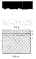
- the B-1 depleted, cobalt-enriched zone 2 overlies the normal cemented carbide phase 1, which contains some B-1 phase.
- the cobalt can be seen as the discrete white areas within the B-1 depleted zone in Fig. 2.
- B-1 phase-depleted zone is formed at sintering temperatures in the absence of nitrogen gas, that is, in an inert atmosphere, as discussed above, nitrogen gas is again introduced into the furnace at an elevated temperature in preparation for the formation of a B-1 phase enriched layer on the surface of the substrate adjacent the B-1 depleted zone.
- Temperatures for this step may range from the cobalt phase melting point (approximately 1300°C-1330°C) to about 1500°C, the preferred range being from about 1400°C to about 1440°C.
- Nitrogen pressure levels can also be varied from about 1 mm to about 1520 mm of Hg pressure.
- Nitrogen pressures greater than about 1520 mm of Hg may be used, and increased nitrogen pressures generally result in an increase in the depth of the B-1 enriched layer.
- the preferred pressure range for this step is from about 500 mm to about 700 mm of Hg.
- Holding times for this sintering step in the presence of nitrogen gas may vary from about 5 minutes to about 100 minutes, with the preferred holding time being in the range of about 20 minutes to about 80 minutes.
- some of the B-1 forming elements namely, Ti, Ta, and/or Nb which are dissolved in the cobalt phase, react with the nitrogen on the surface of the insert to form the corresponding nitride, that is, the B-1 nitride or carbonitride at the surface as shown in Fig.
- the B-1 enriched layer varies with N 2 pressure used in the sintering step, and is typically about 1 micron to about 5 microns deep, although the layer could be up to about 10 microns deep.
- the surface layer of the insert is oxidized by heating the surface for about 5 to about 40 minutes at about 800°C to about 1400°C in an atmosphere which is oxidizing to the B-1 phase, but not oxidizing to tungsten or cobalt.
- lower temperatures are utilized for longer times, and higher temperatures for shorter times.
- a typical oxidation process is described in United States Patent No. 4,018,631.
- the article is subjected to a hydrogen atmosphere containing about 20% by volume of carbon dioxide, and the carbides, nitrides and carbonitrides of the particular metals in the B-1 enriched surface layer become oxidized at the elevated temperature.
- the oxidized surface designated by the numeral 4 in Fig. 4, is perceptible as a thin, faint line of material above the B-1 enriched layer in Figure 3, and serves as a very receptive surface for the subsequently deposited oxide wear layer.
- an oxide wear layer is deposited on the oxidized surface of the article or insert.
- This layer designated by the numeral 5 in Fig. 4, imparts wear resistance to the insert.
- metal oxides are effective, for example, aluminum oxide (AI 2 0 3 ) and zirconium oxide (Zr0 2 ).
- aluminum oxide is the preferred oxide because of its superior wear resistance.
- the metal oxide wear layer is deposited on the insert surface in the manner described and claimed in US-A-3,736,107, incorporated herein by reference. In US-A-3,736,107, a coating layer of aluminum oxide is deposited on a cemented carbide substrate through an intermediate layer.
- FIG. 3 depicts a typical A1 2 0 3 -coated article having a B-1 enriched surface layer and a B-1 depleted subsurface layer.
- the area above the gray A1 2 0 3 layer beginning with the irregular black border at the top of the photomicrograph is simply the backing material used in the photomicrographing process and is not a part of the invention.
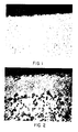
- the substrate having the composition described above is pretreated so as to produce only the B-1 enriched surface layer, as typically depicted in Figure 1.
- This alternative embodiment embraces a method of adhering an oxide coating on a B-1 phase enriched layer of a WC-based article which contains cobalt and at least one carbide, nitride or carbonitride of titanium, and at least one carbide, nitride or carbonitride of tantalum, niobium and/or mixtures thereof and comprises sintering the article in nitrogen gas at a temperature at or above the melting point of the cobalt phase for a period of time sufficient to cause the formation of a B-1 phase enriched layer on the surface of the sintered article; oxidizing the surface of the article; and depositing an oxide wear layer on the oxidized surface.
- the compacted substrate is optionally presintered in vacuum as described for the embodiment discussed above.
- the temperature for the presinter of the substrate is not critical and typically can range from about 400°C to about 600°C.
- the furnace temperature is raised and then the presintered insert is treated in a vacuum or in the presence of other suitable media such as hydrogen gas, argon gas and other inert gases, to eliminate contaminating gases, such as oxygen, which may be present within the insert.
- suitable media such as hydrogen gas, argon gas and other inert gases, to eliminate contaminating gases, such as oxygen, which may be present within the insert.
- Temperature levels are not critical and are typically from about 1000°C to about 1300°C, the preferred temperatures being about 1100°C-1250°C.
- Holding times can vary from about 1 minute to about 120 minutes, the preferred holding time being about 30 minutes-120 minutes.
- the insert is then sintered for about 45 minutes to about 100 minutes in nitrogen gas at or above the melting point of the cobalt phase to form a B-1 phase enriched layer on the surface of the sintered substrate, as shown in Figure 1.
- the temperature at which the substrate is heated to sinter the composition is about 1300°C to about 1500°C, and N 2 pressure levels generally vary from about 1 mm to about 1520 mm of Hg pressure.
- the B-1 phase enriched layer is about 1 to about 5 microns thick, although in certain embodiments the layer is up to about 10 microns thick.
- the melting point of the cobalt phase varies according to the alloying elements in the composition and may be, for example, from about 1300°C to about 1330°C.
- the substrate is oxidized and coated with a metal oxide wear layer as described above to produce the improved inserts useful as cutting tools in accordance with the present invention.
- the inserts prepared by this alternative method are suitable for less vigorous tool applications where the high breakage resistance gained with the inclusion of a B-1 depleted, cobalt-enriched zone is not required.
- An insert was mechanically pressed from powder containing 85.5% by weight tungsten carbide (WC), 6% by weight cobalt (Co), 6% by weight tantalum carbide (TaC) and 2.5% by weight titanium carbide (TiC).
- the insert was then placed in a furnace, and a 45 minute presinter at 500°C in a vacuum was followed by a 45 minute hold at 1236°C. Nitrogen gas was then injected into the furnace at 28 mm Hg and 1340°C. The temperature was steadily raised to 1432°C and the insert was sintered at that temperature for 100 minutes. The insert was then cooled.
- a B-1 phase enriched surface layer resulted with a thickness varying from about 1 micron to about 5 microns.
- the insert was then oxidized and coated with a layer of aluminum oxide (AI 2 0 3 ). The adherence of the A1 2 0 3 to the substrate was good.
- Figure 1 depicts the type of coated insert which typically results when the process set forth in this example is carried out.
- the insert was then contacted with nitrogen gas for 100 minutes at a pressure of 10 mm Hg and a temperature of 1430°C.
- the insert was then cooled.
- the modified surface was then oxidized and coated with AI 2 0 3 . The adherence of the A1 2 0 3 coating to the substrate was good.
- An insert was pressed from powder of the same composition as in Example 1, and then placed on an amorphous carbon coated shelf in a horizontal vacuum sintering furnace. The insert was then presintered at 455°C for 45 minutes in vacuum. Nitrogen (N 2 ) gas was added at the end of this cycle and the temperature was raised to 1260°C. The insert was exposed to N 2 gas for 45 minutes at 600 mm of Hg pressure, and the furnace was then evacuated. Argon (Ar) gas was introduced into the furnace as the temperature was raised to 1447°C. The insert was sintered at 1447°C in Ar gas for 80 minutes at 2 mm of Hg pressure, and Ar gas was replaced by N 2 gas at the end of this cycle. A final sinter was performed in N 2 gas for 20 minutes at 1423°C and 600 mm Hg pressure. The insert was then removed from the furnace and quickly cooled.
- Nitrogen (N 2 ) gas was added at the end of this cycle and the temperature was raised to 1260°C.
- the insert was exposed to N 2
- the resulting B-1 phase enriched surface layer was about 1 micron to 2 microns deep.
- the resulting B-1 phase-depleted, cobalt enriched subsurface layer was about 26 microns deep.
- Figure 2 depicts the type of uncoated insert which typically results when the process set forth in this example is carried out.
- the B-1 enriched phase covered 95% of the surface.
- the amount of coverage depends upon the carbon level of the powder used. A carbon level of 6.15% (prior to sintering) resulted in 95% surface coverage, whereas a carbon level of 6.23% produced about 50%-90% coverage.
- Example 2 An insert of the same composition as in Example 1 was treated to a sequence of steps similar to those in Example 3, except the final sinter was carried out for 80 minutes, rather than 20 minutes.
- Figure 4 is a schematic cross-sectional representation of a substrate which includes a B-1 phase-depleted cobalt-enriched zone 2 above the typical cemented carbide zone 1 having a B-1 phase material dispersed throughout.
- a B-1 enriched layer 3 overlies the B-1 phase-depleted layer 2, and a thin layer of oxidized B-1 phase 4 overlies the B-1 enriched layer 3.
- An oxide wear layer 5 is formed on the oxidized B-1 phase 4.
- Example 2 An insert of the same approximate composition as in Example 1 (with approximately a 6.10% carbon level) was presintered at 450°C for 45 minutes in vacuum. N 2 gas was added at the end of the presinter hold, and the temperature was raised to 1261°C. The insert was exposed to N 2 gas for 45 minutes at 600 mm of Hg pressure, and the furnace was then evacuated. Ar gas was introduced as the temperature was raised to 1444°C. The insert was sintered in the Ar gas for 80 minutes at 2 mm of Hg pressure, and Ar gas was replaced by N 2 gas at the end of this cycle. A final sinter was performed in N 2 gas for 80 minutes at 1427°C and 600 mm Hg pressure. The insert was then quickly cooled.
- Figure 5 illustrates levels of cobalt and titanium throughout the modified areas of an uncoated substrate having the B-1 enriched surface layer and a B-1 depleted, cobalt-enriched subsurface layer.
- the insert having the concentration of Co and Ti shown at the designated depths below the surface in the table below was treated according to the conditions of Example 5.
Landscapes
- Chemical & Material Sciences (AREA)
- Engineering & Computer Science (AREA)
- Materials Engineering (AREA)
- Organic Chemistry (AREA)
- Ceramic Engineering (AREA)
- Mechanical Engineering (AREA)
- Metallurgy (AREA)
- Chemical Kinetics & Catalysis (AREA)
- Structural Engineering (AREA)
- General Chemical & Material Sciences (AREA)
- Inorganic Chemistry (AREA)
- Powder Metallurgy (AREA)
- Ceramic Products (AREA)
- Physical Vapour Deposition (AREA)
- Chemically Coating (AREA)
- Application Of Or Painting With Fluid Materials (AREA)
- Laminated Bodies (AREA)
- Solid-Phase Diffusion Into Metallic Material Surfaces (AREA)
Claims (43)
Priority Applications (1)
| Application Number | Priority Date | Filing Date | Title |
|---|---|---|---|
| AT86105582T ATE44725T1 (de) | 1985-05-06 | 1986-04-23 | Verfahren zur haftverbesserung eines oxidueberzuges an einer mit kobalt angereicherten zone und nach dem genannten prozess hergestellte produkte. |
Applications Claiming Priority (2)
| Application Number | Priority Date | Filing Date | Title |
|---|---|---|---|
| US06/730,511 US4649084A (en) | 1985-05-06 | 1985-05-06 | Process for adhering an oxide coating on a cobalt-enriched zone, and articles made from said process |
| US730511 | 1985-05-06 |
Publications (2)
| Publication Number | Publication Date |
|---|---|
| EP0200991A1 EP0200991A1 (de) | 1986-11-12 |
| EP0200991B1 true EP0200991B1 (de) | 1989-07-19 |
Family
ID=24935667
Family Applications (1)
| Application Number | Title | Priority Date | Filing Date |
|---|---|---|---|
| EP86105582A Expired EP0200991B1 (de) | 1985-05-06 | 1986-04-23 | Verfahren zur Haftverbesserung eines Oxidüberzuges an einer mit Kobalt angereicherten Zone und nach dem genannten Prozess hergestellte Produkte |
Country Status (6)
| Country | Link |
|---|---|
| US (1) | US4649084A (de) |
| EP (1) | EP0200991B1 (de) |
| JP (1) | JPS621853A (de) |
| AT (1) | ATE44725T1 (de) |
| CA (1) | CA1278173C (de) |
| DE (1) | DE3664460D1 (de) |
Families Citing this family (30)
| Publication number | Priority date | Publication date | Assignee | Title |
|---|---|---|---|---|
| CA1313762C (en) * | 1985-11-19 | 1993-02-23 | Sumitomo Electric Industries, Ltd. | Hard sintered compact for a tool |
| CH670874A5 (de) * | 1986-02-04 | 1989-07-14 | Castolin Sa | |
| JPS6379777A (ja) * | 1986-09-24 | 1988-04-09 | 科学技術庁金属材料技術研究所長 | セラミツクス基板上への被覆体の製造法 |
| US4990410A (en) * | 1988-05-13 | 1991-02-05 | Toshiba Tungaloy Co., Ltd. | Coated surface refined sintered alloy |
| FR2635773B1 (fr) * | 1988-08-31 | 1992-02-14 | Aerospatiale | Materiau composite a fibres de renforcement en carbone et son procede de fabrication |
| DE3837006C3 (de) * | 1988-10-31 | 1993-11-18 | Krupp Widia Gmbh | Hartmetall |
| DE68910302T2 (de) * | 1989-02-23 | 1994-04-21 | Toshiba Tungaloy Co Ltd | Diamantbeschichteter Sinterkörper mit hervorragender Adhäsion und Verfahren zu seiner Herstellung. |
| US4923512A (en) * | 1989-04-07 | 1990-05-08 | The Dow Chemical Company | Cobalt-bound tungsten carbide metal matrix composites and cutting tools formed therefrom |
| US5066553A (en) * | 1989-04-12 | 1991-11-19 | Mitsubishi Metal Corporation | Surface-coated tool member of tungsten carbide based cemented carbide |
| JP2762745B2 (ja) * | 1989-12-27 | 1998-06-04 | 住友電気工業株式会社 | 被覆超硬合金及びその製造法 |
| US5181953A (en) * | 1989-12-27 | 1993-01-26 | Sumitomo Electric Industries, Ltd. | Coated cemented carbides and processes for the production of same |
| US5384201A (en) * | 1991-05-31 | 1995-01-24 | Robert Bosch Gmbh | Tool for treating surfaces of structural parts and carrier material for the same |
| SE9200530D0 (sv) * | 1992-02-21 | 1992-02-21 | Sandvik Ab | Haardmetall med bindefasanrikad ytzon |
| CA2092932C (en) * | 1992-04-17 | 1996-12-31 | Katsuya Uchino | Coated cemented carbide member and method of manufacturing the same |
| SE505425C2 (sv) * | 1992-12-18 | 1997-08-25 | Sandvik Ab | Hårdmetall med bindefasanrikad ytzon |
| SE9300376L (sv) * | 1993-02-05 | 1994-08-06 | Sandvik Ab | Hårdmetall med bindefasanriktad ytzon och förbättrat eggseghetsuppförande |
| DE69425459T2 (de) * | 1993-05-25 | 2001-04-12 | Ngk Spark Plug Co., Ltd. | Substrat auf Keramikbasis und Verfahren zu dessen Herstellung |
| SE501913C2 (sv) * | 1993-10-21 | 1995-06-19 | Sandvik Ab | Skär för skärande verktyg |
| SE517474C2 (sv) * | 1996-10-11 | 2002-06-11 | Sandvik Ab | Sätt att tillverka hårdmetall med bindefasanrikad ytzon |
| EP0960219B1 (de) * | 1996-12-24 | 2002-06-19 | Widia GmbH | Verbundkörper, bestehend aus einem hartmetall-, cermet- oder keramiksubstratkörper und verfahren zu seiner herstellung |
| DE19845376C5 (de) * | 1998-07-08 | 2010-05-20 | Widia Gmbh | Hartmetall- oder Cermet-Körper |
| RU2266346C2 (ru) * | 2000-03-24 | 2005-12-20 | Кеннаметал Инк | Металлокерамический резец и способ его изготовления |
| US6638474B2 (en) | 2000-03-24 | 2003-10-28 | Kennametal Inc. | method of making cemented carbide tool |
| SE527173C2 (sv) * | 2003-07-25 | 2006-01-17 | Sandvik Intellectual Property | Sätt att tillverka en finkorning hårdmetall |
| SE529590C2 (sv) * | 2005-06-27 | 2007-09-25 | Sandvik Intellectual Property | Finkorniga sintrade hårdmetaller innehållande en gradientzon |
| DE102006018947A1 (de) * | 2006-04-24 | 2007-10-25 | Tutec Gmbh | Verfahren zur Herstellung eines Hartmetallkörpers, Pulver zur Herstellung eines Hartmetalls und Hartmetallkörper |
| US8252435B2 (en) * | 2006-08-31 | 2012-08-28 | Kyocera Corporation | Cutting tool, process for producing the same, and method of cutting |
| GB201100966D0 (en) * | 2011-01-20 | 2011-03-02 | Element Six Holding Gmbh | Cemented carbide article |
| CN110284038B (zh) * | 2019-04-26 | 2020-07-28 | 中南大学 | 一种具有强(111)织构的pvd涂层及其制备方法 |
| CN121131759A (zh) * | 2025-09-02 | 2025-12-16 | 北京优材百慕航空器材有限公司 | 一种离合器齿面耐磨性强化方法 |
Family Cites Families (22)
| Publication number | Priority date | Publication date | Assignee | Title |
|---|---|---|---|---|
| US32111A (en) * | 1861-04-23 | Apparatus for making roofing-cloth | ||
| US3736107A (en) * | 1971-05-26 | 1973-05-29 | Gen Electric | Coated cemented carbide product |
| US3971656A (en) * | 1973-06-18 | 1976-07-27 | Erwin Rudy | Spinodal carbonitride alloys for tool and wear applications |
| US4063938A (en) * | 1974-03-30 | 1977-12-20 | Gerd Weissman | Method for producing a nitride based hard metal powder |
| US4049876A (en) * | 1974-10-18 | 1977-09-20 | Sumitomo Electric Industries, Ltd. | Cemented carbonitride alloys |
| US4018631A (en) * | 1975-06-12 | 1977-04-19 | General Electric Company | Coated cemented carbide product |
| US4150195A (en) * | 1976-06-18 | 1979-04-17 | Sumitomo Electric Industries, Ltd. | Surface-coated cemented carbide article and a process for the production thereof |
| DE2717842C2 (de) * | 1977-04-22 | 1983-09-01 | Fried. Krupp Gmbh, 4300 Essen | Verfahren zur Oberflächenbehandlung von gesinterten Hartmetallkörpern |
| US4239536A (en) * | 1977-09-09 | 1980-12-16 | Sumitomo Electric Industries, Ltd. | Surface-coated sintered hard body |
| JPS5487719A (en) * | 1977-12-23 | 1979-07-12 | Sumitomo Electric Industries | Super hard alloy and method of making same |
| SE425003B (sv) * | 1978-02-28 | 1982-08-23 | Sandvik Ab | Modifikation av molybden-volfram-karbonitrid enligt kraven i patentet 7800756-4 |
| SE417818B (sv) * | 1979-09-03 | 1981-04-13 | Sandvik Ab | Keramisk legering vesentligen omfattande aluminiumoxid samt nitrider och/eller karbonitrider av en eller flera metaller tillhorande grupperna iv b, v b och vi b i periodiska systemet samt en eller flera ... |
| IL58548A (en) * | 1979-10-24 | 1983-07-31 | Iscar Ltd | Sintered hard metal products having a multi-layer wearresistant coating |
| US4350528A (en) * | 1980-06-12 | 1982-09-21 | Trw Inc. | Method for diffusion bonding workpieces and article fabricated by same |
| JPS5716161A (en) * | 1980-07-02 | 1982-01-27 | Ngk Spark Plug Co Ltd | Preparation of coating tip for cutting |
| US4357382A (en) * | 1980-11-06 | 1982-11-02 | Fansteel Inc. | Coated cemented carbide bodies |
| USRE32111E (en) | 1980-11-06 | 1986-04-15 | Fansteel Inc. | Coated cemented carbide bodies |
| CA1174438A (en) * | 1981-03-27 | 1984-09-18 | Bela J. Nemeth | Preferentially binder enriched cemented carbide bodies and method of manufacture |
| US4501786A (en) * | 1981-12-16 | 1985-02-26 | General Electric Company | Coated product with oxide wear layer |
| US4548786A (en) * | 1983-04-28 | 1985-10-22 | General Electric Company | Coated carbide cutting tool insert |
| US4497874A (en) * | 1983-04-28 | 1985-02-05 | General Electric Company | Coated carbide cutting tool insert |
| US4556607A (en) * | 1984-03-28 | 1985-12-03 | Sastri Suri A | Surface coatings and subcoats |
-
1985
- 1985-05-06 US US06/730,511 patent/US4649084A/en not_active Expired - Lifetime
-
1986
- 1986-04-23 EP EP86105582A patent/EP0200991B1/de not_active Expired
- 1986-04-23 AT AT86105582T patent/ATE44725T1/de not_active IP Right Cessation
- 1986-04-23 DE DE8686105582T patent/DE3664460D1/de not_active Expired
- 1986-04-25 CA CA000507564A patent/CA1278173C/en not_active Expired - Lifetime
- 1986-05-01 JP JP61099536A patent/JPS621853A/ja active Pending
Also Published As
| Publication number | Publication date |
|---|---|
| EP0200991A1 (de) | 1986-11-12 |
| US4649084A (en) | 1987-03-10 |
| ATE44725T1 (de) | 1989-08-15 |
| DE3664460D1 (en) | 1989-08-24 |
| JPS621853A (ja) | 1987-01-07 |
| CA1278173C (en) | 1990-12-27 |
Similar Documents
| Publication | Publication Date | Title |
|---|---|---|
| EP0200991B1 (de) | Verfahren zur Haftverbesserung eines Oxidüberzuges an einer mit Kobalt angereicherten Zone und nach dem genannten Prozess hergestellte Produkte | |
| US4548786A (en) | Coated carbide cutting tool insert | |
| US4497874A (en) | Coated carbide cutting tool insert | |
| JP2598791B2 (ja) | チップフォーミング工作用焼結体 | |
| EP0603143B1 (de) | Carbid-Metall-Verbundstoff mit einer in der Oberfläche angereicheten Binderphase | |
| EP0438916B2 (de) | Beschichteter Hartmetallkörper und Verfahren zu seiner Herstellung | |
| US3999954A (en) | Hard metal body and its method of manufacture | |
| US5310605A (en) | Surface-toughened cemented carbide bodies and method of manufacture | |
| EP0337696B1 (de) | Oberflächenbeschichtetes, zementiertes Carbid | |
| JP3934160B2 (ja) | 結合相富化した表面領域を有する超硬合金の製造方法 | |
| USRE35538E (en) | Sintered body for chip forming machine | |
| KR100835694B1 (ko) | 초경합금 공구 및 그 제조방법 | |
| US5283030A (en) | Coated cemented carbides and processes for the production of same | |
| US20080251962A1 (en) | Multicomponent ceramics powder, method of manufacturing multicomponent ceramics powder, sintered body, and method of manufacturing sintered body | |
| US20090011267A1 (en) | Sintered Cemented Carbides Using Vanadium as Gradient Former | |
| JP2005529236A (ja) | 硬質金属支持体およびその製造方法 | |
| US5856032A (en) | Cermet and process for producing it | |
| US20080224344A1 (en) | Method of making a cemented carbide body | |
| JP4170402B2 (ja) | 窒化された表面領域を備えたチタニウム基炭窒化物合金 | |
| JP2000336451A (ja) | 改質焼結合金、被覆焼結合金及びその製造方法 | |
| JP2828511B2 (ja) | 表面被覆TiCN基サーメット | |
| JP2828512B2 (ja) | 被覆TiCN基サーメット | |
| JP2771336B2 (ja) | 被覆TiCN基サーメット | |
| JP2004517207A (ja) | 加工用刃具およびその製造方法 | |
| CA1256274A (en) | Coated carbide cutting tool insert |
Legal Events
| Date | Code | Title | Description |
|---|---|---|---|
| PUAI | Public reference made under article 153(3) epc to a published international application that has entered the european phase |
Free format text: ORIGINAL CODE: 0009012 |
|
| AK | Designated contracting states |
Kind code of ref document: A1 Designated state(s): AT BE CH DE FR GB IT LI SE |
|
| 17P | Request for examination filed |
Effective date: 19870428 |
|
| 17Q | First examination report despatched |
Effective date: 19880511 |
|
| RAP1 | Party data changed (applicant data changed or rights of an application transferred) |
Owner name: CARBOLOY INC. |
|
| 17Q | First examination report despatched |
Effective date: 19880511 |
|
| GRAA | (expected) grant |
Free format text: ORIGINAL CODE: 0009210 |
|
| AK | Designated contracting states |
Kind code of ref document: B1 Designated state(s): AT BE CH DE FR GB IT LI SE |
|
| PG25 | Lapsed in a contracting state [announced via postgrant information from national office to epo] |
Ref country code: LI Effective date: 19890719 Ref country code: CH Effective date: 19890719 Ref country code: BE Effective date: 19890719 Ref country code: AT Effective date: 19890719 |
|
| REF | Corresponds to: |
Ref document number: 44725 Country of ref document: AT Date of ref document: 19890815 Kind code of ref document: T |
|
| REF | Corresponds to: |
Ref document number: 3664460 Country of ref document: DE Date of ref document: 19890824 |
|
| ET | Fr: translation filed | ||
| ITF | It: translation for a ep patent filed | ||
| REG | Reference to a national code |
Ref country code: CH Ref legal event code: PL |
|
| PG25 | Lapsed in a contracting state [announced via postgrant information from national office to epo] |
Ref country code: SE Effective date: 19900201 |
|
| PLBE | No opposition filed within time limit |
Free format text: ORIGINAL CODE: 0009261 |
|
| STAA | Information on the status of an ep patent application or granted ep patent |
Free format text: STATUS: NO OPPOSITION FILED WITHIN TIME LIMIT |
|
| 26N | No opposition filed | ||
| ITTA | It: last paid annual fee | ||
| REG | Reference to a national code |
Ref country code: GB Ref legal event code: IF02 |
|
| PGFP | Annual fee paid to national office [announced via postgrant information from national office to epo] |
Ref country code: FR Payment date: 20050408 Year of fee payment: 20 |
|
| PGFP | Annual fee paid to national office [announced via postgrant information from national office to epo] |
Ref country code: GB Payment date: 20050420 Year of fee payment: 20 |
|
| PGFP | Annual fee paid to national office [announced via postgrant information from national office to epo] |
Ref country code: DE Payment date: 20050421 Year of fee payment: 20 |
|
| PGFP | Annual fee paid to national office [announced via postgrant information from national office to epo] |
Ref country code: IT Payment date: 20050430 Year of fee payment: 20 |
|
| PG25 | Lapsed in a contracting state [announced via postgrant information from national office to epo] |
Ref country code: GB Free format text: LAPSE BECAUSE OF EXPIRATION OF PROTECTION Effective date: 20060422 |
|
| REG | Reference to a national code |
Ref country code: GB Ref legal event code: PE20 |