EP0200437A2 - Mécanisme élévateur à commande par pression fluidique - Google Patents
Mécanisme élévateur à commande par pression fluidique Download PDFInfo
- Publication number
- EP0200437A2 EP0200437A2 EP86302940A EP86302940A EP0200437A2 EP 0200437 A2 EP0200437 A2 EP 0200437A2 EP 86302940 A EP86302940 A EP 86302940A EP 86302940 A EP86302940 A EP 86302940A EP 0200437 A2 EP0200437 A2 EP 0200437A2
- Authority
- EP
- European Patent Office
- Prior art keywords
- piston
- ram
- piston rod
- cylinder
- package
- Prior art date
- Legal status (The legal status is an assumption and is not a legal conclusion. Google has not performed a legal analysis and makes no representation as to the accuracy of the status listed.)
- Granted
Links
- 239000012530 fluid Substances 0.000 claims abstract description 16
- 230000033001 locomotion Effects 0.000 claims abstract description 6
- 230000000694 effects Effects 0.000 abstract description 3
- 238000004804 winding Methods 0.000 description 12
- 239000004753 textile Substances 0.000 description 5
- RRLHMJHRFMHVNM-BQVXCWBNSA-N [(2s,3r,6r)-6-[5-[5-hydroxy-3-(4-hydroxyphenyl)-4-oxochromen-7-yl]oxypentoxy]-2-methyl-3,6-dihydro-2h-pyran-3-yl] acetate Chemical compound C1=C[C@@H](OC(C)=O)[C@H](C)O[C@H]1OCCCCCOC1=CC(O)=C2C(=O)C(C=3C=CC(O)=CC=3)=COC2=C1 RRLHMJHRFMHVNM-BQVXCWBNSA-N 0.000 description 4
- 230000008878 coupling Effects 0.000 description 3
- 238000010168 coupling process Methods 0.000 description 3
- 238000005859 coupling reaction Methods 0.000 description 3
- 238000007789 sealing Methods 0.000 description 3
- 230000006835 compression Effects 0.000 description 2
- 238000007906 compression Methods 0.000 description 2
- 229910001209 Low-carbon steel Inorganic materials 0.000 description 1
- 229910000831 Steel Inorganic materials 0.000 description 1
- 238000006073 displacement reaction Methods 0.000 description 1
- 238000000926 separation method Methods 0.000 description 1
- 229910001220 stainless steel Inorganic materials 0.000 description 1
- 239000010935 stainless steel Substances 0.000 description 1
- 239000010959 steel Substances 0.000 description 1
Images
Classifications
-
- D—TEXTILES; PAPER
- D01—NATURAL OR MAN-MADE THREADS OR FIBRES; SPINNING
- D01H—SPINNING OR TWISTING
- D01H9/00—Arrangements for replacing or removing bobbins, cores, receptacles, or completed packages at paying-out or take-up stations ; Combination of spinning-winding machine
-
- B—PERFORMING OPERATIONS; TRANSPORTING
- B65—CONVEYING; PACKING; STORING; HANDLING THIN OR FILAMENTARY MATERIAL
- B65H—HANDLING THIN OR FILAMENTARY MATERIAL, e.g. SHEETS, WEBS, CABLES
- B65H54/00—Winding, coiling, or depositing filamentary material
- B65H54/02—Winding and traversing material on to reels, bobbins, tubes, or like package cores or formers
- B65H54/40—Arrangements for rotating packages
- B65H54/52—Drive contact pressure control, e.g. pressing arrangements
-
- B—PERFORMING OPERATIONS; TRANSPORTING
- B65—CONVEYING; PACKING; STORING; HANDLING THIN OR FILAMENTARY MATERIAL
- B65H—HANDLING THIN OR FILAMENTARY MATERIAL, e.g. SHEETS, WEBS, CABLES
- B65H54/00—Winding, coiling, or depositing filamentary material
- B65H54/70—Other constructional features of yarn-winding machines
-
- B—PERFORMING OPERATIONS; TRANSPORTING
- B65—CONVEYING; PACKING; STORING; HANDLING THIN OR FILAMENTARY MATERIAL
- B65H—HANDLING THIN OR FILAMENTARY MATERIAL, e.g. SHEETS, WEBS, CABLES
- B65H63/00—Warning or safety devices, e.g. automatic fault detectors, stop-motions ; Quality control of the package
- B65H63/02—Warning or safety devices, e.g. automatic fault detectors, stop-motions ; Quality control of the package responsive to reduction in material tension, failure of supply, or breakage, of material
- B65H63/024—Warning or safety devices, e.g. automatic fault detectors, stop-motions ; Quality control of the package responsive to reduction in material tension, failure of supply, or breakage, of material responsive to breakage of materials
- B65H63/036—Warning or safety devices, e.g. automatic fault detectors, stop-motions ; Quality control of the package responsive to reduction in material tension, failure of supply, or breakage, of material responsive to breakage of materials characterised by the combination of the detecting or sensing elements with other devices, e.g. stopping devices for material advancing or winding mechanism
- B65H63/0364—Warning or safety devices, e.g. automatic fault detectors, stop-motions ; Quality control of the package responsive to reduction in material tension, failure of supply, or breakage, of material responsive to breakage of materials characterised by the combination of the detecting or sensing elements with other devices, e.g. stopping devices for material advancing or winding mechanism by lifting or raising the package away from the driving roller
-
- B—PERFORMING OPERATIONS; TRANSPORTING
- B65—CONVEYING; PACKING; STORING; HANDLING THIN OR FILAMENTARY MATERIAL
- B65H—HANDLING THIN OR FILAMENTARY MATERIAL, e.g. SHEETS, WEBS, CABLES
- B65H2701/00—Handled material; Storage means
- B65H2701/30—Handled filamentary material
- B65H2701/31—Textiles threads or artificial strands of filaments
Definitions
- the present invention relates to an improved fluid power-operated ram.
- One application for a fluid power-operated ram is in the lifting of a yarn package out of contact with its drive roll in textile winding machinery.
- the diameter of the build-up of yarn on the support core of the package increases and consequently if the drive roll is in a fixed position, which is normally the case, the package support axis of rotation moves relative to the axis of the drive roll.
- the present invention provides a fluid power-operated drive ram comprising a cylinder, a piston slidable in the cylinder, and a piston rod extending through one end of the cylinder and through the piston, characterised by means for selectively engaging the piston rod with either the piston or the cylinder for fluid pressure-operated actuation of relative movement between the piston and the cylinder, and by the fact that the piston rod is freely slidable with respect to the other of the piston and cylinder.
- the drive ram has two separate conditions, one in which the piston rod is movable relative to both the piston and the cylinder, and the other in which the piston rod is locked relative to either the piston or the cylinder but movable relative to the other of those two components.
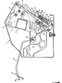
- a textile winding machine 1 has a pair of quadrants 2 (only one of which can be seen in the drawing) each fixed on a spindle 3 allowing rotation of the quadrants about the axis of rotation of the spindle, the two quadrants supporting, between them, a square-section channel beam 4 which supports the conventional package arms (not shown) of the winder. Since the manner in which the package arms engage the freely rotatable support core for a yarn package to be wound, is conventional, the drawing has been simplified by omission of those components in order to allow a better appreciation of the important elemei of the present invention.
- the two quadrants 2 are to be rotated in the clockwise direction through a given incremental angle which is just sufficient to draw the surface of the package, which may be conical or cylindrical, out of contact with the friction drive roll to a position which is always at a given constant spacing from the friction drive roll.
- winding ceases and no further increase in the package diameter occurs.
- the package When winding is to resume, the package is lowered into contact with the friction drive roll to impart driving rotation to the package at machine speed.
- the re-acceleration of the package may occur either through resumed frictional drive contact with the drive roll (not shown) or through engagement with a separate drive roll which serves only to accelerate the package to machine speed.
- Clockwise rotation of the segments 2 is achieved by virtue of a drive ram in accordance with the present invention, generally designated 5.
- the piston rod 6 of such drive ram is pinned, at 7 to a bracket 8 of one of the quadrants and thus the application of fluid pressure to the ram 5 by way of a quick-fit fluid pressure coupling 9 results in descent of the piston rod 6 through the desired travel.
- the drawing also shows the exterior of a vibration damper 10 which may, for example, incorporate a preloading spring and will normally bias the quadrants in the clockwise direction to hold the package in contact with the friction drive roll under a given contact force. Furthermore, the damper 10 will prevent bouncing of the package out of contact with its friction drive roll during the highspeed rotation of the package taking place upon yarn winding.
- a vibration damper may, for example, be of the type disclosed and claimed in our European Patent Application No. 85303173.0.
- the piston rod 6 is freely slidable relative to the piston 11, by virtue of the fact that a washer 16 of the ram has its internal diameter just large enough to clear the external surface of the piston rod 6 but as a very close fit therewith.
- the top end of the cylinder 22 of the ram is closed by a plug member 17 held captive by means of a circlip 18 and having an extension 17a which abuts the washer 16 and is surrounded by a further washer 19 whose axially opposite faces are not parallel to one another, so that in effect the washer 19 forms a wedge.
- the washer 19 is held in place by a further circlip housed in an internal groove of the piston 11.
- the constant thickness (i.e. parallel-faced) washer 16 which will hereafter be referred to as the locking washer is biased towards the plug 17 closing the ram cylinder 22, by virtue of a helical compression spring 23.
- the piston 11 is itself urged towards the closing plug 17 by way of a separate, stronger helical compression spring 20.
- the cylinder 22 of the ram includes a slot 21 to accommodate the movable free end of the drive arm 12 for the yarn bridge arm 13.
- seals in the ram for example one sealing the piston rod 6 relative to the closing plug 17, a further sealing the exterior of the closing plug 17 relative to the internal wall of the cylinder 22, yet another sealing the exterior of the piston 11 relative to the internal wall of the cylidner, and a last seal at the end of the piston 11 remote from the closing plug 17 to seal the pist6n with respect to the piston rod 6.
- the piston will press the locking washer 16 flat against the lower end face of the closing plug 17, restoring the locking washer 16 to a configuration in which it is exactly perpendicular to the longitudinal axis of the piston rod 6, thereby allowing the piston rod 6 to slide freely once more during growth of the build-up of yarn on the package.
- the locking member 16 is carried by the piston 11 of the ram
- the cylinder it would alternatively be possible for the cylinder to be the ram component which carries the locking member 16, in which case the orientation of the ram would advantageously be changed so that longitudinal axis of the piston rod 6 is now upwardly divergent leftwardly (rather than rightwardly as shown in the drawing) relative to the vertical and operation of the ram pushes the piston rod to pivot the quadrants 2 clockwise, rather than pulling them as shown in the drawing.
- the precise pivoting mechanism used to tip the locking washer 16 may vary from that shown in the drawing.
- a projection for example a radially extending peg
- the washer may be stepped rather than being wedge-shaped as in the drawing.
- the piston rod may be of a steel rod, for example of stainless steel, and the washer may be of case-hardened mild steel.
Landscapes
- Engineering & Computer Science (AREA)
- Textile Engineering (AREA)
- Mechanical Engineering (AREA)
- Quality & Reliability (AREA)
- Replacing, Conveying, And Pick-Finding For Filamentary Materials (AREA)
- Winding Filamentary Materials (AREA)
Applications Claiming Priority (2)
| Application Number | Priority Date | Filing Date | Title |
|---|---|---|---|
| GB8511390 | 1985-05-03 | ||
| GB08511390A GB2174455B (en) | 1985-05-03 | 1985-05-03 | Improved fluid-operated ram |
Publications (3)
| Publication Number | Publication Date |
|---|---|
| EP0200437A2 true EP0200437A2 (fr) | 1986-11-05 |
| EP0200437A3 EP0200437A3 (en) | 1988-03-30 |
| EP0200437B1 EP0200437B1 (fr) | 1990-03-07 |
Family
ID=10578660
Family Applications (1)
| Application Number | Title | Priority Date | Filing Date |
|---|---|---|---|
| EP86302940A Expired EP0200437B1 (fr) | 1985-05-03 | 1986-04-18 | Mécanisme élévateur à commande par pression fluidique |
Country Status (4)
| Country | Link |
|---|---|
| US (1) | US4684074A (fr) |
| EP (1) | EP0200437B1 (fr) |
| DE (1) | DE3669301D1 (fr) |
| GB (1) | GB2174455B (fr) |
Cited By (1)
| Publication number | Priority date | Publication date | Assignee | Title |
|---|---|---|---|---|
| EP0249381A1 (fr) * | 1986-06-12 | 1987-12-16 | Hollingsworth (U.K.) Limited | Amortisseur de vibrations |
Families Citing this family (6)
| Publication number | Priority date | Publication date | Assignee | Title |
|---|---|---|---|---|
| FR2621304B1 (fr) * | 1987-10-02 | 1990-02-02 | Granger Maurice | Dispositif de regulation de la distribution de bandes de materiaux enroules |
| JP2627648B2 (ja) * | 1988-08-22 | 1997-07-09 | 株式会社ナブコ | 駆動装置及びその駆動装置を用いたブレーキ装置 |
| DE19515601A1 (de) * | 1995-04-28 | 1996-10-31 | Fritz Stahlecker | Einrichtung zum Dämpfen von Schwingungen einer Auflaufspule an Spinn-, Zwirn- oder Spulmaschinen |
| IT1319229B1 (it) * | 2000-10-20 | 2003-09-26 | Savio Macchine Tessili Spa | Dispositivo portarocche perfezionato per avvolgimento di filato conpressione regolata, particolarmente per ritorcitoi a doppia torsione. |
| DE10060237A1 (de) * | 2000-12-05 | 2002-06-06 | Schlafhorst & Co W | Verfahren zum Betreiben einer Kreuzspulen herstellenden Textilmaschine |
| CN102586962A (zh) * | 2012-01-22 | 2012-07-18 | 经纬纺织机械股份有限公司 | 转杯纺纱机阻尼装置 |
Family Cites Families (11)
| Publication number | Priority date | Publication date | Assignee | Title |
|---|---|---|---|---|
| US1816352A (en) * | 1927-09-21 | 1931-07-28 | Universal Winding Co | Winding machine |
| US1958060A (en) * | 1930-12-06 | 1934-05-08 | Foster Machine Co | Stop motion |
| US2866662A (en) * | 1953-05-08 | 1958-12-30 | Nemeth George | Clamp holder and clamp for pipe pushers |
| GB1330154A (en) * | 1970-12-09 | 1973-09-12 | Westinghouse Brake & Signal | Fluid-pressure actuators |
| GB1391267A (en) * | 1971-08-06 | 1975-04-16 | Plessey Co Ltd | Step-by-step linear adjustment devices |
| US4195790A (en) * | 1975-09-27 | 1980-04-01 | W. Schlafhorst & Co. | Method and device for discontinuing operation of a winding device after a thread break occurs |
| US4090643A (en) * | 1976-09-17 | 1978-05-23 | The Terrell Corporation | Hot melt applicator |
| US4165829A (en) * | 1977-11-09 | 1979-08-28 | Fedorov Stanislav G | Method of feeding electrode wire and apparatus for performing same |
| IT1124200B (it) * | 1979-10-12 | 1986-05-07 | Ultraflex Di Aldo & Giorgio Ga | Martinetto a doppio effetto con mezzi di arresto per le due posizionei di fine corsa agenti anche in assenza di pressione del fluido motore |
| DE3235789C2 (de) * | 1982-09-28 | 1989-05-18 | Saurer-Allma Gmbh, 8960 Kempten | Schwenkbarer Spulenhalter |
| GB2134183B (en) * | 1983-01-24 | 1986-02-05 | Automotive Products Plc | A fluid-operable actuator for an aircraft undercarriage |
-
1985
- 1985-05-03 GB GB08511390A patent/GB2174455B/en not_active Expired
-
1986
- 1986-04-18 EP EP86302940A patent/EP0200437B1/fr not_active Expired
- 1986-04-18 DE DE8686302940T patent/DE3669301D1/de not_active Expired - Fee Related
- 1986-04-30 US US06/857,267 patent/US4684074A/en not_active Expired - Fee Related
Cited By (1)
| Publication number | Priority date | Publication date | Assignee | Title |
|---|---|---|---|---|
| EP0249381A1 (fr) * | 1986-06-12 | 1987-12-16 | Hollingsworth (U.K.) Limited | Amortisseur de vibrations |
Also Published As
| Publication number | Publication date |
|---|---|
| EP0200437A3 (en) | 1988-03-30 |
| EP0200437B1 (fr) | 1990-03-07 |
| DE3669301D1 (de) | 1990-04-12 |
| US4684074A (en) | 1987-08-04 |
| GB2174455B (en) | 1988-09-28 |
| GB2174455A (en) | 1986-11-05 |
| GB8511390D0 (en) | 1985-06-12 |
Similar Documents
| Publication | Publication Date | Title |
|---|---|---|
| US5029762A (en) | Yarn winding apparatus and method | |
| KR0174295B1 (ko) | 엘리베이터용 조속기 | |
| EP0200437A2 (fr) | Mécanisme élévateur à commande par pression fluidique | |
| KR900003084B1 (ko) | 평행추나 리프트케이지를 위한 캐치장치(catch device) | |
| US3941320A (en) | Braking device in coil support frame or cradle | |
| NO304181B1 (no) | Sikkerhetsanordning for heiser | |
| EP0249381A1 (fr) | Amortisseur de vibrations | |
| DE3238376C2 (de) | Fadenspeicher | |
| DE2528067A1 (de) | Geschwindigkeitsbegrenzer fuer aufzuege | |
| KR910009600B1 (ko) | 자동조절장치를 갖춘 원판 브레이크 | |
| GB1249247A (en) | Method of and apparatus for winding a yarn in which the yarn tension is controlled | |
| US3934830A (en) | Spooling mechanism | |
| US5447301A (en) | Governor foot assembly for cyclically sensing the height of a feeder sheet pile | |
| US2046550A (en) | Thread winding mechanism | |
| DE3235789C2 (de) | Schwenkbarer Spulenhalter | |
| CN1296544C (zh) | 用于探纱的具有弹簧止动件的纱线喂给装置 | |
| DE3403733A1 (de) | Vorrichtung zum steuern einer packmittelbremse | |
| US4576342A (en) | Apparatus for lifting a wound yarn package | |
| CN86108224A (zh) | 汽车鼓式制动器 | |
| US6254028B1 (en) | Device for damping oscillations of a winding bobbin in spinning, twisting or winding machines | |
| DE1952726B2 (de) | Spulvorrichtung | |
| JPS62238846A (ja) | 織機における経糸送り出し異常検出方法 | |
| US4164859A (en) | Wire accumulator | |
| DE3827345A1 (de) | Entlang einer spinnmaschine verfahrbares wartungsgeraet mit mitteln zum suchen eines fadens von einer spule | |
| JPH076102B2 (ja) | ストップ装置 |
Legal Events
| Date | Code | Title | Description |
|---|---|---|---|
| PUAI | Public reference made under article 153(3) epc to a published international application that has entered the european phase |
Free format text: ORIGINAL CODE: 0009012 |
|
| AK | Designated contracting states |
Kind code of ref document: A2 Designated state(s): CH DE FR IT LI |
|
| PUAL | Search report despatched |
Free format text: ORIGINAL CODE: 0009013 |
|
| AK | Designated contracting states |
Kind code of ref document: A3 Designated state(s): CH DE FR IT LI |
|
| 17P | Request for examination filed |
Effective date: 19880518 |
|
| 17Q | First examination report despatched |
Effective date: 19880913 |
|
| GRAA | (expected) grant |
Free format text: ORIGINAL CODE: 0009210 |
|
| AK | Designated contracting states |
Kind code of ref document: B1 Designated state(s): CH DE FR IT LI |
|
| ITF | It: translation for a ep patent filed | ||
| REF | Corresponds to: |
Ref document number: 3669301 Country of ref document: DE Date of ref document: 19900412 |
|
| ET | Fr: translation filed | ||
| PLBE | No opposition filed within time limit |
Free format text: ORIGINAL CODE: 0009261 |
|
| STAA | Information on the status of an ep patent application or granted ep patent |
Free format text: STATUS: NO OPPOSITION FILED WITHIN TIME LIMIT |
|
| 26N | No opposition filed | ||
| PGFP | Annual fee paid to national office [announced via postgrant information from national office to epo] |
Ref country code: FR Payment date: 19920309 Year of fee payment: 7 |
|
| PGFP | Annual fee paid to national office [announced via postgrant information from national office to epo] |
Ref country code: DE Payment date: 19920318 Year of fee payment: 7 Ref country code: CH Payment date: 19920318 Year of fee payment: 7 |
|
| ITTA | It: last paid annual fee | ||
| PG25 | Lapsed in a contracting state [announced via postgrant information from national office to epo] |
Ref country code: LI Effective date: 19930430 Ref country code: CH Effective date: 19930430 |
|
| PG25 | Lapsed in a contracting state [announced via postgrant information from national office to epo] |
Ref country code: FR Effective date: 19931229 |
|
| REG | Reference to a national code |
Ref country code: CH Ref legal event code: PL |
|
| PG25 | Lapsed in a contracting state [announced via postgrant information from national office to epo] |
Ref country code: DE Effective date: 19940101 |
|
| REG | Reference to a national code |
Ref country code: FR Ref legal event code: ST |
|
| PG25 | Lapsed in a contracting state [announced via postgrant information from national office to epo] |
Ref country code: IT Free format text: LAPSE BECAUSE OF NON-PAYMENT OF DUE FEES;WARNING: LAPSES OF ITALIAN PATENTS WITH EFFECTIVE DATE BEFORE 2007 MAY HAVE OCCURRED AT ANY TIME BEFORE 2007. THE CORRECT EFFECTIVE DATE MAY BE DIFFERENT FROM THE ONE RECORDED. Effective date: 20050418 |