EP0200375B1 - Support pour gouverne d'un bateau à moteur - Google Patents
Support pour gouverne d'un bateau à moteur Download PDFInfo
- Publication number
- EP0200375B1 EP0200375B1 EP86302430A EP86302430A EP0200375B1 EP 0200375 B1 EP0200375 B1 EP 0200375B1 EP 86302430 A EP86302430 A EP 86302430A EP 86302430 A EP86302430 A EP 86302430A EP 0200375 B1 EP0200375 B1 EP 0200375B1
- Authority
- EP
- European Patent Office
- Prior art keywords
- steering
- shaft
- positioning
- steering handle
- tiltable member
- Prior art date
- Legal status (The legal status is an assumption and is not a legal conclusion. Google has not performed a legal analysis and makes no representation as to the accuracy of the status listed.)
- Expired
Links
Images


Classifications
-
- B—PERFORMING OPERATIONS; TRANSPORTING
- B63—SHIPS OR OTHER WATERBORNE VESSELS; RELATED EQUIPMENT
- B63H—MARINE PROPULSION OR STEERING
- B63H25/00—Steering; Slowing-down otherwise than by use of propulsive elements; Dynamic anchoring, i.e. positioning vessels by means of main or auxiliary propulsive elements
- B63H25/06—Steering by rudders
- B63H25/08—Steering gear
- B63H25/10—Steering gear with mechanical transmission
Definitions
- the present invention relates to a small-sized watercraft having a seat on the rearward position of the hull and a steering handle disposed on the hull forwardly of the seat and particularly to a unit for supporting the steering handle.
- an operator may take the seat and manipulate the steering handle to operate or drive the watercraft.
- the watercraft includes a steering handle which is not tiltable for an operator to take an attitude compatible with his physical features or preferences.
- US-A-3 487 712 discloses a steering wheel assembly for controlling a rudder or drive unit of a watercraft.
- the assembly includes a tubular member or steering column having the steering shaft rotatably disposed therein.
- the shaft is turned within the column by means of the steering wheel, the hub of which is secured on the end of the shaft.
- Actuating means for a flexible push-pull cable connected to the rudder or drive unit includes a pinion secured on the end of the shaft opposite from the steering wheel.
- the pinion is rotatable with the shaft to drive a rack carrying a movable member of the cable.
- a mounting bracket assembly supports the steering wheel assembly for pivotal tilt movement about a transverse axis through a given range in a generally vertical plane.
- the bracket assembly is secured to a supporting structure such as the transversely extending dashboard of the watercraft.
- Locking means comprising a transversely extending lever engageable with any one of a plurality of notches on a quadrant projecting downwardly from the steering column, is provided for locking the steering wheel assembly in any one of a plurality of positions.
- US-A-2 829 090 discloses a boat steering control comprising a mounting bracket rigidly secured to the rearward face of the dashboard, a steering column extending between vertical ears of the bracket, and a steering shaft extending axially through the steering column.
- An intermediate tube portion of the steering column has a horizontal bore through which a pivot and clamping bolt extends.
- the steering column is swingable in a vertical plane about the pivot bolt and is held in angularly adjusted position by another bolt.
- the projecting lower end of the steering shaft carries thereon an actuator in the form of a double-sheave winding drum, tiller ropes being wound around the drum.
- DE-C-348 872 discloses a steering arrangement for motor boats in which the bearing for the steering column is carried on a quadrant-like member pivotable about a horizontal axis.
- the pivotable quadrant-like member carrying the steering column bearing includes an arcuate slot centred on the axis through which a clamping bolt passes to secure the member in a chosen position and the member is commonly journalled with an second pivotable quadrant-like member linking the end of the steering column to the remainder of the steering mechanism.
- the linkage to the remainder of the steering mechanism includes a clamping bolt passing through an arcuate slot, centred on the common axis, in the second quadrant-like member.
- the present invention provides a steering handle supporting unit suitable for use in a watercraft, said unit comprising a steering column mounted in a mounting wall; a steering shaft rotatably supported in said steering column, a tiltable member supported by said steering shaft and carrying a steering handle, said tiltable member being angularly adjustable about a pivot shaft in the fore-and-aft direction of the hull of the watercraft; and manually-operable unlocking means and positioning means (24) for locking said tiltable member at a selected angular position, characterized in that, for use in a watercraft comprising a hull, a seat on the rearward portion of said hull and a mounting wall disposed in said hull forwardly of said seat, the tiltable member is pivotally connected to the steering shaft by way of the pivot shaft, and in that the manually-operable unlocking means is disposed between said tiltable member and said steering shaft.
- Figure 1 is a left-hand side view of a small-sized watercraft incorporating a tiltable steering handle which is one embodiment of the present invention.
- Figure 2 is a back elevational view of the watercraft shown in Figure 1.
- Figure 3 is an enlarged cross-sectional view of the primary parts of a unit for supporting the tiltable steering handle.
- Figure 4 is a back elevational view of the unit shown in Figure 3.
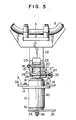
- Figure 5 is a front elevational view of a modification of the unit for supporting the tiltable steering handle.
- a watercraft having a hull 1 which comprises a lower hull portion 2 and an upper deck portion 3.
- the lower and upper portions 2 and 3 are made of a fiber reinforced plastic (FRP) and sealingly joined with each other at their peripheral flanges 4.
- FRP fiber reinforced plastic
- the deck portion 3 extends from the bow of the hull to the stern of the same and an openable hood 5 provided on the forward portion of the deck to cover an engine (not shown) which is mounted within the hull 1.
- Behind the hood 5 is an upright wall, shown by broken line 5A in Figure 1, which has its lower end sealingly mounted on a mounting wall 3A formed integrally with a top wall facing the rearward portion of the hood 5.
- a steering unit S is mounted in the mounting wall 3A.
- the portion of the deck 3 extending rearwardly from the steering unit S is formed integrally with a seat mount 7 having a central raised part and foot rests 8 located on the opposite sides of the seat mount 7 at a lowered level, as best seen from Figure 2.
- a seat 9 is rigidly supported on the top of the seat mount 7.
- the rearward portion of the seat 9 extends rearwardly and downwardly to form a riding slope 10.
- the steering unit S comprises a steering column 12 extending through an opening 11 in the mounting wall 3A.
- the steering column 12 is of a hollow cylinder configuration and includes an outwardly extending flange 13 formed integrally thereon about the outer periphery thereof.
- the steering column 12 is inserted upwardly into the opening 11 of the mounting wall 3A and then the flange 13 thereof is applied and attached to the bottom face of the mounting wall 3A by means of any suitable fastening means such as bolts 14.
- the flange 13 is positioned on the steering column 12 at a central position between the opposite ends thereof.
- the steering column 12 will have its upwardly and downwardly extending portions of substantially the same length about the mounting wall 3A.
- a steering shaft 15 Prior to the mounting of the steering column 12 on the mounting wall 3A, a steering shaft 15 is passed through the hollow portion of the steering column 12.
- the steering shaft 15 is rotatably supported within flanged bearing bushings 16 which are disposed within the upper and lower ends of the hollow steering column 12, respectively.
- the steering shaft 15 has a support flange 17 formed thereon at a position adjacent to the upper bearing bushing 16 and a cylinder-shaped support boss 18 upwardly extending from the support flange 17.
- the support boss 18 includes a transverse bore 19 formed therein within which flanged pivot bushings 20 are rigidly supported at the opposite ends of the bore 19.
- Pivot shaft means (bolt-nut means) 21 extends through the transverse bore 19 of the support boss 18 and rotatably supported by the pivot bushings 20 therein.
- the pivot shaft means 21 supports a tiltable member 22 which is preferably of aluminium and which can angularly be positioned about the pivot shaft means 21 in the fore-and-aft direction of the hull.
- the top of the tiltable member 22 detachably supports a bar-like steering handle 6.
- each of the pivot bushings 20 is disposed outwardly of the bore 19 in the support boss 18 and engaged at its outer face by the inner face of each of bifurcated legs 23 on the tiltable member 22.
- the tiltable member 22 can be locked at an angular position by positioning means 24 which comprises a positioning stopper 25, a positioning pin 26 and a set spring 27.
- the positioning stopper 25 is a plate-shaped member which upwardly extends from and welded to the top face of the support boss 18 at one side.
- the positioning stopper 25 includes a plurality of tapered positioning apertures 28 (three in the illustrated embodiment) which is arranged on a circle having a center on the pivot shaft 21.
- the central one of the tapered positioning apertures 28 serves to position the tiltable member 22 at its neutral location and the remaining apertures 28 are used to position the tiltable member 22 at its forwardly and rearwardly tilted locations, respectively.
- the positioning pin 26 includes an inner tapered end 29 adapted to penetrate into one of the tapared positioning apertures 28 in the positioning stopper 25 and an outer unlocking end 30 manually operated by an operator.
- the positioning pin 26 movably passes through a pin aperture 31 formed in the tiltable member 22.
- the set spring 27 is located within a spring receiver 32 which is mounted on the tiltable member 22 at one side and outwardly extends therefrom.
- the set spring 27 has one end engaged by the outer end of the spring receiver 32 which the other end thereof seated on an intermediate flange 33 on the positioning pin 26.
- the positioning pin 26 is resiliently biased against the stopper 25 under the action of the set spring 27 such that the inner end 29 of the positioning pin 26 can positively be held in one of the positioning apertures 28 in the positioning stopper 25.
- the steering shaft 15 downwardly extends beyond the lower end of the steering column 12 which is located downwardly of the mounting wall 3A.
- the downwardly extending portion of the steering shaft 15 includes a square-shaped boss 34 which is fitted into the corresponding opening of a rotatable plate-shaped steering force transmitting member 35.
- a lock nut 36 is threadingly engaged onto the lowermost threaded end of the steering shaft 15 and then tightened against the rotatable member 35 such that the latter can be rotated with the steering shaft 15.
- the rotatable member 35 includes a rotary piece 37 extending downwardly from the bottom thereof, which piece 37 is connected with one end of a steering force transmitting relay member 38 in the form of a cable for converting a rotational movement into a linear movement.
- the rotatable steering force transmitting member 35 includes two engagement lugs 39 spaced away from each other about the outer periphery of the member 35. Between these engagement lugs 39 is received a stopper 40 which extends downwardly from the mounting flange 13 of the steering column 12.
- the other end of the relay member 38 may be connected with steering nozzle means (not shown) on the stern of the hull and used to change the direction of the moving watercraft.
- the outer unlocking end 30 of the positioning pin 26 is manually pulled out against the action of the set spring 27 to disengage the inner end 29 of the positioning pin 26 from the positioning aperture 28.
- the positioning pin 26 is simply released to penetrate its inner end 29 into a selected one of the positioning apertures 28 under the action of the set spring 27, so that the tiltable member 22 and thus the steering handle 6 can automatically be locked at the desired angular position. In such a manner, the operator can take an optimum attitude for the steering handle 6, depending on his physical features or preferences.
- FIG. 5 there is shown a modification of the embodiment shown in Figures 1 to 4, in which the pivot shaft 21 is disposed above the positioning means 24.
- the steering handle 6 can less be moved to provide the same amount of tilt. This leads to a reduced size in the tiltable steering unit.
- the structure shown in Figure 4 includes the positioning pin 26 on the tiltable member 22 and the positioning apertures 28 in the steering shaft 15, the positioning pin 26 and positioning apertures 28 may be provided respectively on the steering shaft 15 and tiltable member 22, as shown in Figure 5.
- the present invention provides a tiltable steering unit which can angularly be adjusted depending on the operator's physical features or preferences by manually unlocking the positioning means to adjust the steering handle into a desired angular position and thereafter automatically locking the steering handle at that desired angular position.
Landscapes
- Chemical & Material Sciences (AREA)
- Engineering & Computer Science (AREA)
- Combustion & Propulsion (AREA)
- Mechanical Engineering (AREA)
- Ocean & Marine Engineering (AREA)
- Steering Devices For Bicycles And Motorcycles (AREA)
- Steering Controls (AREA)
Claims (8)
- Ensemble de support de poignée de gouverne propre a être utilisé dans un canot automobile, cet ensemble comprenant une colonne de direction (12) montée dans une paroi de montage (3A), un arbre de direction (15) monté à rotation dans ladite colonne de direction (12), un élément inclinable (22) supporté par ledit arbre de direction (15) et portant une poignée de gouverne (6), la position angulaire dudit élément inclinable (22) étant réglable autour d'un boulon d'articulation (21) dans la direction avant-arrière de la coque (1) du canot automobile, et des moyens de déverrouillage manuel (30) ainsi que des moyens de positionnement (24) pour verrouiller ledit élément inclinable (22) dans une position angulaire choisie, caractérisé en ce qu'en vue de son utilisation dans un canot automobile comprenant une coque (1) un siège (9) dans la partie arrière de cette coque et une paroi de montage (3A) disposée dans la coque en avant dudit siège, l'élément inclinable (22) est raccordé de façon pivotante à l'arbre de direction (15) au moyen du boulon d'articulation (21), et en ce que les moyens de déverrouillage manuel (30) sont disposés entre ledit élément inclinable (22) et ledit arbre de direction (15).
- Ensemble de support de poignée de gouverne selon la revendication 1, dans lequel une collerette de support (17) est formée sur l'arbre de direction (15), un moyeu de support de forme cylindrique (18) s'étend vers le haut à partir de la collerette de support (17), une forure transversale (19) est formée dans le moyeu de support (18), forure (19) aux extrémités opposées de laquelle sont montées rigidement des douilles de pivotement à bride (20), et la bride de chacune des douilles de pivotement (20) est disposée en dehors de la forure (19) dans le moyeu de support (18) et est en contact par sa face externe avec la face interne de l'une associée de deux branches de bifurcation (23) de l'élément inclinable (22).
- Ensemble de support de poignée de gouverne selon la revendication 1 ou 2, dans lequel les moyens de positionnement (24) comprennent un arrêt de positionnement (25) pourvu de plusieurs ouvertures coniques de positionnement (28), une cheville de positionnement (26) et un ressort d'enclenchement (27).
- Ensemble de support de poignée de gouverne selon la revendication 3, dans lequel la cheville de positionnement (26) est située sur l'arbre de direction (15).
- Ensemble de support de poignée de gouverne selon l'une quelconque des revendications 1 à 4, dans lequel les moyens de positionnement (24) sont disposés au-dessous du boulon d'articulation (21) et au-dessus de la colonne de direction (12).
- Ensemble de support de poignée de gouverne selon l'une quelconque des revendications 1 à 3, dans lequel le boulon d'articulation (21) est disposé au-dessous desdits moyens de positionnement (24).
- Ensemble de support de poignée de gouverne selon la revendication 6 considérée sous la dépendance de la revendication 3, dans lequel l'arrêt de positionnement (25) est disposé sur l'arbre de direction (15).
- Ensemble de support de poignée de gouverne selon la revendication 6 considérée sous la dépendance de la revendication 3, dans lequel la cheville de positionnement (26) est située sur l'élément inclinable (22).
Applications Claiming Priority (2)
| Application Number | Priority Date | Filing Date | Title |
|---|---|---|---|
| JP70516/85 | 1985-04-03 | ||
| JP60070516A JPS61229690A (ja) | 1985-04-03 | 1985-04-03 | 小型滑走艇のハンドル支持装置 |
Publications (2)
| Publication Number | Publication Date |
|---|---|
| EP0200375A1 EP0200375A1 (fr) | 1986-12-10 |
| EP0200375B1 true EP0200375B1 (fr) | 1991-07-03 |
Family
ID=13433770
Family Applications (1)
| Application Number | Title | Priority Date | Filing Date |
|---|---|---|---|
| EP86302430A Expired EP0200375B1 (fr) | 1985-04-03 | 1986-04-02 | Support pour gouverne d'un bateau à moteur |
Country Status (4)
| Country | Link |
|---|---|
| US (1) | US4726311A (fr) |
| EP (1) | EP0200375B1 (fr) |
| JP (1) | JPS61229690A (fr) |
| DE (1) | DE3680020D1 (fr) |
Families Citing this family (21)
| Publication number | Priority date | Publication date | Assignee | Title |
|---|---|---|---|---|
| JPH0645435Y2 (ja) * | 1988-07-23 | 1994-11-24 | 川崎重工業株式会社 | 小型滑走艇のステアリング装置 |
| JP2772423B2 (ja) * | 1988-08-29 | 1998-07-02 | スズキ株式会社 | ウォータビークルのステアリング装置 |
| US4941421A (en) * | 1988-09-23 | 1990-07-17 | Suzuki Jidosha Kogyo Kabushiki Kaisha | Steering mechanism for aquatic vehicle |
| US5048444A (en) * | 1989-01-11 | 1991-09-17 | Moore John E | Adjustable wheel for yacht pedestal steerer |
| US5136894B1 (en) * | 1990-08-31 | 1996-10-15 | Bankers Trust Co | Tiltable marine steering helm |
| US5282437A (en) * | 1992-08-21 | 1994-02-01 | Avillez De Basto Luiz J | Personal marine transport |
| US5527004A (en) * | 1993-02-24 | 1996-06-18 | Helix Air, Inc. | Control system for aircraft |
| US5427336A (en) * | 1993-02-24 | 1995-06-27 | Haggerty; Matthew K. | Dual control mechanism for aircraft |
| US5622132A (en) * | 1995-12-29 | 1997-04-22 | Mardikian 1991 Irrevocable Trust | Shock-absorbing steering system for personal watercraft |
| JP3904286B2 (ja) * | 1996-11-29 | 2007-04-11 | ヤマハ発動機株式会社 | 小型船艇のステアリング装置 |
| FR2762823B1 (fr) * | 1997-04-30 | 1999-07-30 | Marcel Bellens | Engin de loisir nautique motorise |
| JP3904290B2 (ja) * | 1997-06-26 | 2007-04-11 | ヤマハ発動機株式会社 | 小型船舶の操舵装置 |
| JP3454728B2 (ja) | 1998-10-08 | 2003-10-06 | 川崎重工業株式会社 | 小型滑走艇のステアリング構造 |
| JP3860015B2 (ja) * | 2001-10-30 | 2006-12-20 | 本田技研工業株式会社 | 小型艇の操舵装置 |
| JP2005212569A (ja) | 2004-01-28 | 2005-08-11 | Kawasaki Heavy Ind Ltd | 小型滑走艇 |
| US7559576B1 (en) | 2004-07-07 | 2009-07-14 | Polaris Industries Inc. | Vehicle with adjustable steering |
| US20060017273A1 (en) * | 2004-07-26 | 2006-01-26 | Woerman Gary R | Steering control handle bars |
| CN101021733B (zh) * | 2007-02-07 | 2010-05-26 | 浙江诺力机械股份有限公司 | 手柄位置调整机构 |
| US8037781B2 (en) * | 2008-07-23 | 2011-10-18 | Yamaha Motor Manufacturing Corporation Of America | Telescoping steering system and water vehicle including the same |
| TW201408542A (zh) * | 2012-08-21 | 2014-03-01 | Joy Ride Technology Co Ltd | 衝浪板轉向裝置 |
| USD726632S1 (en) * | 2013-08-28 | 2015-04-14 | Kawasaki Jukogyo Kabushiki Kaisha | Steering handle holder for watercraft |
Family Cites Families (15)
| Publication number | Priority date | Publication date | Assignee | Title |
|---|---|---|---|---|
| US756670A (en) * | 1903-07-27 | 1904-04-05 | Walter L Marr | Steering-gear for automobiles. |
| DE348872C (de) * | 1920-11-21 | 1922-02-18 | Aeg | Steuervorrichtung fuer Motorboote u. dgl. |
| US1785783A (en) * | 1928-03-08 | 1930-12-23 | Mohr Julius | Toy vehicle |
| US2826090A (en) * | 1955-01-27 | 1958-03-11 | Supreme Foundry Inc | Boat steering controls |
| US3168156A (en) * | 1962-01-11 | 1965-02-02 | Yale & Towne Inc | Steering and control handle |
| US3092857A (en) * | 1962-04-23 | 1963-06-11 | Fred L Churchman | Water sled |
| US3395930A (en) * | 1966-03-07 | 1968-08-06 | Int Harvester Co | Tiltable steering wheel |
| US3487712A (en) * | 1967-09-25 | 1970-01-06 | Brunswick Corp | Steering control means for watercraft |
| US3559611A (en) * | 1968-03-14 | 1971-02-02 | Tucker Martin | Amphibious vehicle |
| GB1291904A (en) * | 1970-08-08 | 1972-10-04 | Scooter Ski Ltd | Improvements in and relating to propulsion units for water craft |
| JPS493755U (fr) * | 1972-04-17 | 1974-01-12 | ||
| CA1015222A (en) * | 1972-09-06 | 1977-08-09 | Hiroshi Ono | Aquatic vehicle |
| US3948206A (en) * | 1974-09-06 | 1976-04-06 | Still Water Properties, N.V. | Jet powered watercraft |
| JPS5753730U (fr) * | 1980-09-16 | 1982-03-29 | ||
| US4481838A (en) * | 1982-04-19 | 1984-11-13 | Douglas Components Corporation | Adjustable steering shaft |
-
1985
- 1985-04-03 JP JP60070516A patent/JPS61229690A/ja active Pending
-
1986
- 1986-04-02 US US06/847,249 patent/US4726311A/en not_active Expired - Lifetime
- 1986-04-02 EP EP86302430A patent/EP0200375B1/fr not_active Expired
- 1986-04-02 DE DE8686302430T patent/DE3680020D1/de not_active Expired - Lifetime
Also Published As
| Publication number | Publication date |
|---|---|
| EP0200375A1 (fr) | 1986-12-10 |
| DE3680020D1 (de) | 1991-08-08 |
| US4726311A (en) | 1988-02-23 |
| JPS61229690A (ja) | 1986-10-13 |
Similar Documents
| Publication | Publication Date | Title |
|---|---|---|
| EP0200375B1 (fr) | Support pour gouverne d'un bateau à moteur | |
| US12377947B2 (en) | Outboard motor that is removable from transom clamp bracket | |
| US6146221A (en) | Steering lock for outboard motor | |
| US6352456B1 (en) | Marine propulsion apparatus with adjustable tiller handle | |
| US7267587B2 (en) | Steering system of outboard motor | |
| US7311571B1 (en) | Hydraulic steering device for a marine propulsion system | |
| AU4412089A (en) | Sail-wing and controls for a sail craft | |
| US6283806B1 (en) | Locking mechanism for an outboard motor | |
| JPH04266590A (ja) | 舶用装置 | |
| US6758705B1 (en) | Foot pedal kit for trolling motor | |
| US6684803B1 (en) | Watercraft steering apparatus with joystick | |
| US5056450A (en) | Personal watercraft with extendable handlebar | |
| US3889620A (en) | Symmetrical sail assembly | |
| US5030145A (en) | Manually operable boat propeller | |
| US5868591A (en) | Swivel lock for outboard motor | |
| US5207170A (en) | Marine propulsion unit control system | |
| US3659475A (en) | Remote throttle and steering control unit | |
| US6776671B2 (en) | Trolling motor steering linkage system | |
| US3799102A (en) | Boat propulsion system | |
| US4402675A (en) | Outboard motor tilt mechanism | |
| US5358434A (en) | Mounting apparatus for trolling motor | |
| US4348193A (en) | Foot steering apparatus for outboard motor boats | |
| JP2000053088A (ja) | 船外機の操舵角固定装置 | |
| US3251333A (en) | Outboard motor steering bracket | |
| US3559612A (en) | Stick steering kit for boats |
Legal Events
| Date | Code | Title | Description |
|---|---|---|---|
| PUAI | Public reference made under article 153(3) epc to a published international application that has entered the european phase |
Free format text: ORIGINAL CODE: 0009012 |
|
| AK | Designated contracting states |
Kind code of ref document: A1 Designated state(s): DE GB |
|
| PUAB | Information related to the publication of an a document modified or deleted |
Free format text: ORIGINAL CODE: 0009199EPPU |
|
| PUAF | Information related to the publication of a search report (a3 document) modified or deleted |
Free format text: ORIGINAL CODE: 0009199SEPU |
|
| R17D | Deferred search report published (corrected) |
Effective date: 19861210 |
|
| RA1 | Application published (corrected) |
Date of ref document: 19861210 Kind code of ref document: A1 |
|
| 17P | Request for examination filed |
Effective date: 19870310 |
|
| 17Q | First examination report despatched |
Effective date: 19880524 |
|
| GRAA | (expected) grant |
Free format text: ORIGINAL CODE: 0009210 |
|
| AK | Designated contracting states |
Kind code of ref document: B1 Designated state(s): DE GB |
|
| REF | Corresponds to: |
Ref document number: 3680020 Country of ref document: DE Date of ref document: 19910808 |
|
| PLBE | No opposition filed within time limit |
Free format text: ORIGINAL CODE: 0009261 |
|
| STAA | Information on the status of an ep patent application or granted ep patent |
Free format text: STATUS: NO OPPOSITION FILED WITHIN TIME LIMIT |
|
| 26N | No opposition filed | ||
| REG | Reference to a national code |
Ref country code: GB Ref legal event code: IF02 |
|
| PGFP | Annual fee paid to national office [announced via postgrant information from national office to epo] |
Ref country code: GB Payment date: 20020327 Year of fee payment: 17 |
|
| PGFP | Annual fee paid to national office [announced via postgrant information from national office to epo] |
Ref country code: DE Payment date: 20020410 Year of fee payment: 17 |
|
| PG25 | Lapsed in a contracting state [announced via postgrant information from national office to epo] |
Ref country code: GB Free format text: LAPSE BECAUSE OF NON-PAYMENT OF DUE FEES Effective date: 20030402 |
|
| PG25 | Lapsed in a contracting state [announced via postgrant information from national office to epo] |
Ref country code: DE Free format text: LAPSE BECAUSE OF NON-PAYMENT OF DUE FEES Effective date: 20031101 |
|
| GBPC | Gb: european patent ceased through non-payment of renewal fee |
Effective date: 20030402 |