EP0198547B1 - Fahrerhaus - Google Patents
Fahrerhaus Download PDFInfo
- Publication number
- EP0198547B1 EP0198547B1 EP86200606A EP86200606A EP0198547B1 EP 0198547 B1 EP0198547 B1 EP 0198547B1 EP 86200606 A EP86200606 A EP 86200606A EP 86200606 A EP86200606 A EP 86200606A EP 0198547 B1 EP0198547 B1 EP 0198547B1
- Authority
- EP
- European Patent Office
- Prior art keywords
- operator
- cab
- post
- station
- glazing
- Prior art date
- Legal status (The legal status is an assumption and is not a legal conclusion. Google has not performed a legal analysis and makes no representation as to the accuracy of the status listed.)
- Expired
Links
- 238000001125 extrusion Methods 0.000 claims description 13
- 230000014759 maintenance of location Effects 0.000 claims description 12
- 230000004438 eyesight Effects 0.000 claims description 10
- 230000000694 effects Effects 0.000 claims description 2
- 238000003306 harvesting Methods 0.000 description 17
- 239000011521 glass Substances 0.000 description 16
- 238000004378 air conditioning Methods 0.000 description 3
- 239000000463 material Substances 0.000 description 2
- 230000000717 retained effect Effects 0.000 description 2
- 230000000007 visual effect Effects 0.000 description 2
- 239000011358 absorbing material Substances 0.000 description 1
- 238000010276 construction Methods 0.000 description 1
- 238000009429 electrical wiring Methods 0.000 description 1
- 230000007613 environmental effect Effects 0.000 description 1
- 230000004313 glare Effects 0.000 description 1
- 238000009434 installation Methods 0.000 description 1
- 238000007789 sealing Methods 0.000 description 1
Images


Classifications
-
- B—PERFORMING OPERATIONS; TRANSPORTING
- B60—VEHICLES IN GENERAL
- B60J—WINDOWS, WINDSCREENS, NON-FIXED ROOFS, DOORS, OR SIMILAR DEVICES FOR VEHICLES; REMOVABLE EXTERNAL PROTECTIVE COVERINGS SPECIALLY ADAPTED FOR VEHICLES
- B60J1/00—Windows; Windscreens; Accessories therefor
- B60J1/02—Windows; Windscreens; Accessories therefor arranged at the vehicle front, e.g. structure of the glazing, mounting of the glazing
-
- B—PERFORMING OPERATIONS; TRANSPORTING
- B62—LAND VEHICLES FOR TRAVELLING OTHERWISE THAN ON RAILS
- B62D—MOTOR VEHICLES; TRAILERS
- B62D33/00—Superstructures for load-carrying vehicles
- B62D33/06—Drivers' cabs
- B62D33/0617—Drivers' cabs for tractors or off-the-road vehicles
Definitions
- the present invention relates generally to operator's cabs such as mounted on self-propelled crop harvesting machines, such as combines, and, more particularly, to improvements in the construction of the operator's cab to maximize the operator's vision of the crop harvesting operation.
- Modern self-propelled crop harvesting machines are generally equipped with an enclosed operator's cab in which the operator is seated to control the harvesting operation of his machine.
- Such operator's cabs are generally provided with environmental controls, such as air conditioning and sound absorbing materials, to improve the quality of the work environment for the operator.
- Operator cabs are generally mounted at an elevated position on the crop harvesting machine to afford the operator a field of view of the harvesting operation relating to the gathering of crop material from the field in which he is operating.
- the cab enclosure is provided with a number of transparent panels, normally glass, supported from vertical posts extending between the floor member and the roof member of the cab.
- the glass panels are supported from rubber glazing elements that encircle each panel of glass.
- Each glazing element is supported from one of the vertical posts or other portions of the cab housing to completely encircle the perimeter of the transparent panels.
- each joint between adjacent glass panels is provided with two glazing elements plus a structural element of the cab separating and supporting the adjacent glazing elements. While this approach offers easy assembly and serviceability, a great amount of visual obstruction is encountered. Accordingly, it would be desirable to provide an operator's cab, such as for a self-propelled crop harvesting machine, that provides glass support having minimal visual obstruction without loss of structural strength of the structural elements.
- DE-A-2.060.371 has already proposed to provide a support post with an angled extension and a glazing element attached thereto at a location generally within the width of the obstructing dimension of this post, i.e. the dimension extending generally perpendicular to the line of sight from the operator's station.
- This extension and the corresponding glazing element thereby are hidden from the operator behind said post whereby they do not obstruct the field of view of the operator.
- This arrangement permits the glazing element to engage and support one transparent panel but fails to provide the same advantageous solution when a pair of adjacent transparent panels have to be supported and retained by one support post.
- the present invention is in the form of an operator's cab which provides a field of view to an operator positioned at an operator's station within the cab; which includes support posts and an enclosure with transparent panels supported at least partially by said posts; and of which at least one of said posts is positioned within said field of view and has an obstructing dimension extending generally perpendicular to the line of sight from the operator's station; said at least one post being provided with a glazing element disposed substantially within the width of said obstructing dimension when seen in the direction of said line of sight and comprising an elongated extrusion having an attachment portion engageable with said post to effect attachment therewith and further also comprising a panel retention portion;
- this cab being characterized in that the panel retention portion is engageable with a pair of corresponding transparent panels for support and retention thereof; and the extrusion is constructed such that said corresponding transparent panels are positionally fixed without any portion of the corresponding support post being positioned therebetween.
- the glazing elements are positioned behind the corresponding support posts so that they are substantially completely hidden from the operator behind said support posts whereby they do not detract from the operator's field of vision.
- said obstructing width of each support post extending perpendicular to the line of sight of the operator is less than the eye spacing of the operator to permit full vision of the harvesting operation at a resonable distance outside the cab.
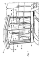
- a perspective view of the operator's cab mounted on a self-propelled crop harvesting machine commonly referred to as a combine
- Any left and right references are used as a matter of convenience and are determined by standing at the rear of the machine, facing the forward end, the direction of travel.
- the self-propelled crop harvesting machine 10 is fragmentarily shown and represents a conventional combine harvester; however, one skilled in the art will readily realize that the principles of the instant invention will not be limited to the type of machine on which the operator's cab is mounted.
- the operator's cab according to the present invention may be used on a wide variety of machines, inclusive on tractors and on machines other than agricultural machines.
- the cab according to the invention even may be used on pull-type machines in the exceptional situation where pull-type machines are equipped with their own cab, although clearly the operator's cab according to the invention will be used most commonly on self-propelled machines.
- the cab 12 includes a floor member 14, a roof member 16 vertically spaced above the floor member 14 and an enclosure 18 extending around and encompassing an operator's station 20, shown in the form of a seat, steering wheel, etc. Supporting the roof member 16 above the floor member 14 and at least partially supporting the enclosure 18, the operator's cab 12 is provided with a plurality of support posts; namely, a right rear support post 22, a right side post 24, two front support posts 25, a left side post 26 and a left rear support post 28, spaced around the periphery of the enclosure 18.
- the operator 30 positioned at the operator's station 20 is provided with a field of vision extending radially from the right rear support post 22 to the left rear support post 28.
- the enclosure 18 includes a right side window 31 supported between the right rear support post 22 and the right side post 24, a right side transparent panel 33 (typically glass) supported between the right side post 24 and the right front post 25a, a large curved front transparent panel 35 supported between the right front post 25a and the left front post 25b, a left side transparent panel 37 supported between the left front post 25b and the left side post 26, and a transparent access door 40 pivotally supported for movement about a hinge axis 42 mounted on the left side post 26 and closing against the left rear support post 28.
- a hinge axis 42 mounted on the left side post 26 and closing against the left rear support post 28.
- the enclosure 18 can optionally incorporate a rear window 39 supported between the right rear post 22 and the left rear post 28.
- the support posts forwardly of the operator's station 20, namely, the right side post 24, the two front posts 25 and the left side post 26, are oriented to minimize the obstruction to the field of view of the operator 30.
- the obstructing dimension D i.e., the dimension of the support posts perpendicular to the line of sight L of the operator 30, for each forward support post 24,25,26 is less than the eye spacing of the operator 30.
- the glazing elements 45,65 supporting and retaining the respective transparent panels are located on the opposing side of the respective support posts from the operator's station 20 in such a manner that the glazing elements 45,65 are hidden behind the respective support posts and, thereby, do not further detract from the operator's field of vision.
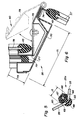
- FIG. 3 shows that the right rear support post 22 is constructed as a generally hollow box- like member, permitting the passage of wiring, heater hoses, air conditioning hoses, etc. between the roof member 16 and the floor member 14.
- the oblong glazing element 45 supporting the rear window 39 is attached to a leg 47 formed in the support post 22.
- the left rear support post 28 is constructed as a mirror image of the right rear support post 22 with the left rear post 28 having a seal for the closure of the access door 40 instead of the window 31.
- Both rear posts 22,28 are generally vertically oriented.
- the right side support post 24 can best be seen.
- the forward support posts 24,25,26 are inclined forwardly and/or outwardly with respect to a vertical line to locate the respective transparent panels 33,35,37 at an angle to reduce glare problems.
- the right side post 24 is formed into an oblong hollow beam 50 having a major dimension 51 greater than a minor dimension 53.
- the beam 50 is oriented such that the major dimension 51 is parallel to the line of sight L of the operator 30 and, therefore, the minor dimension 53 becomes the obstructing dimension D.
- the leg 56 of the post 24 supports a seal 49 for the side window 31.
- Another leg 58 permits attachment of the oblong glazing element 45 at a position behind the beam 50 to permit the support and retention of the right side transparent panel 33 without exposing the glazing element 45 to the line of sight L of the operator 30.
- the width of the oblong glazing element 45 is less than the minor dimension 53, permitting the glazing element 45 to be hid entirely behind the post 24 and out of the field of vision of the operator 30.
- the hollow beam 50 can permit the passage of wiring, etc. between the floor member 14 and the roof member 16.
- Each support post 25 is formed as a generally U-shaped channel 60 having inwardly directed legs 62.
- the obstructing dimension D is again smaller than the eye spacing of the operator 30 to permit a full view of the harvesting operation at a reasonable distance beyond the enclosure 18.
- a glazing extrusion 65 engages the channel member 60 and supports and retains adjacent glass panels 33,35. While Fig. 5 depicts the right front post 25a, the right front post 25a and the left front post 25b are constructed identically, except that the left front post 25b is provided with a glazing extrusion 65 that supports and retains adjacent transparent panels 35,37.
- the glazing extrusion 65 is formed in two integral portions, an attachment portion 66 and a glass retention portion 68.
- the somewhat bulbous attachment portion 66 is adapted to be received within the channel member 60 and retained in position by the inwardly directed legs 62.
- a hole 67 extends axially through the attachment portion 66. Since the glazing extrusion 65 extends between the roof member 16 and floor member 14, the hole 67 in the attachment portion 66 could be utilized as a drain tube for air conditioning condensate or the like.
- the glass retention portion 68 projects outwardly from the channel member 60 and is adapted to receive and retain the edges of the adjacent glass panels 33,35 or 35,37, respectively. As best seen in Fig.
- the glazing extrusion 65 supports the glass panels 33,35 from the support post 25a without the need of a structural member extending therebetween. Since the size of the glass retention portion 68 is smaller than the obstructing dimension D of the channel member 60, the glazing extrusion 65 can be hid out of the line of sight L of the operator 30 behind the channel member 60 as is best seen in Fig. 2.
- the left side post 26 is formed as an elongated member 70 having a major dimension 71 greater than a minor dimension 73.
- the elongated member 70 is oriented such that the major dimension 71 is positioned parallel to the line of sight L of the operator 30 and, hence, the minor dimension 73 becomes the obstructing dimension D.
- the left side post 26 comprises, as seen in cross-section, a pair of box-like members which are spaced apart generally in the direction of the line of sight L and which have a width corresponding to the obstructing dimension D.
- the innermost box-like member is generally rectangular in cross-section while that the outermost box-like member is generally triangular in cross-section.
- the box-like members are interconnected by a connecting member of reduced width as seen in a direction perpendicular to the line of sight L and which is positioned generally at one side of the generally elongate cross-sectional configuration 70 thus defining a recess between the box-like members and the connecting members.
- the outermost box-like member of the left side post 26 is provided with a leg 74 at the opposing side thereof from the operator's station 20 and to which is attached the oblong glazing element 45 for the support and retention of the left side panel 37.
- the leg 74 and the glazing element 45 are positioned substantially within the width of the minor dimension 73 and generally behind the support post 26 when seen in the direction of the line of sight L from the operator's station.
- the access door 40 is pivotally supported by a hinge assembly 75 attached to the outermost box-like member of the left side post 26 and defining the hinge axis 42.
- the door 40 is formed by a channel like frame 77 extending around the periphery of the door 40 and supporting a glazing element 45 for retaining a glass panel 78 to permit visibility through the door 40.
- a seal 79 is affixed to the innermost box-like member of the left side post 26 at the opposing side thereof from the operator's station 20, i.e. generally within the recess defined between the innermost and outermost box-like members and the connecting member.
- a further seal 79 is also provided to the left rear support post 28. Both seals 79 permit a sealing of the door 40 when in the closed position.
- the hinge assembly 75 and the one side member of the generally rectangular door frame 77 to which the hinge assembly 75 is attached are positioned, as can be best seen in Fig. 6, substantially within the recess defined between the innermost and outermost box-like members and the connecting member of the left side support 26 when the access door 40 is in the closed position. Furthermore, when the door 40 is in said closed position, said components, i.e. the hinge assembly 75 and the one door side member also are substantially positioned within the width of the obstructing dimension D as seen in the direction of the line of sight L.
- the forward support posts 24,25,26 can be inclined out of a vertical orientation to angle the glass panels 33,35,37 for functional improvement, as well as to provide an asthetically pleasing appearance.
- the instant invention provides enclosed passages for hoses and electrical wiring to improve the aesthetic appearance of the cab 12 from both the inside and the outside. It further is also an advantage of this invention that firm support for the glass panels is provided without stress points and that installation and removal of glass panels can be easily accomplished.
- the operator's cab subject of the invention may be used on all sorts of machines inclusive on all sorts of harvesting machines.
- the operator's station on a variety of machines may be designed such as to be able to receive a single standardized operator's cab, which thus can be utilized in a universal application on a plurality of machines.
- Such a cab thus may be offered on the market as an independent structure for mounting on any machine designed to receive such a cab.
Landscapes
- Engineering & Computer Science (AREA)
- Mechanical Engineering (AREA)
- Chemical & Material Sciences (AREA)
- Combustion & Propulsion (AREA)
- Transportation (AREA)
- Body Structure For Vehicles (AREA)
- Harvester Elements (AREA)
Claims (5)
- Fahrerhaus (12), das einem an einer Fahrerstation (20) in dem Fahrerhaus (12) befindlichen Fahrer ein Sichtfeld bietet und Stützsäulen (25ab) und eine Umschließung (18) mit transparenten Scheiben (33,35,37) einschließt, die zumindestens teilweise durch die Säulen (25ab) gehaltert sind, wobei zumindestens eine der Säulen (25ab) in dem Sichtfeld angeordnet ist und eine Verdeckungsabmessung (D) aufweist, die sich allgemein senkrecht zur Sichtlinie (L) von der Fahrerstation (20) aus erstreckt und wobei die zumindestens eine Säule (25ab) mit einem Verglasungselement (65) versehen ist, das im wesentlichen innerhalb der Breite der Verdeckungsabmessung (D) bei Betrachtung in der Richtung der Sichtlinie (L) angeordnet ist und ein langgestrecktes Stangpreßteil umfaßt, das einen Befestigungsabschnitt (66), der mit der Säule (25ab) zu seiner Befestigung hieran in Eingriff bringbar ist, und weiterhin einen Scheibenhalteabschnitt (68) umfaßt,
dadurch gekennzeichnet, daß
der Scheibenhalteabschnitt (68) mit zwei entsprechenden transparenten Scheiben (33,35;35,37) zu deren Abstützung und Halterung in Eingriff bringbar ist, und
das Strangpreßteil derart ausgebildet ist, daß die genannten entsprechenden transparenten Scheiben (33,35;35,37) positionsmäßig festgelegt sind, ohne daß irgend ein Teil der entsprechenden Stützsäule (25ab) zwischen diesen Scheiben angeordnet ist. - Fahrerhaus (12) nach Anspruch 1,
dadurch gekennzeichnet, daß das
Verglasungselement (65) auf der der Fahrerstation (20) entgegengesetzten Seite der entsprechenden Stützsäule (25ab) angeordnet ist, so daß das Verglasungselement (65) im wesentlichen vollständig für den Fahrer hinter der Säule (25ab) verdeckt ist, wodurch dieses Verglasungselement (65) das Sichtfeld des Fahrers nicht versperrt. - Fahrerhaus (12) nach Anspruch 1 oder 2,
dadurch gekennzeichnet, daß der Befestigungsabschnitt (66) des Verglasungs-Strangpreßteils eine Öffnung (67) aufweist, die sich in Axialrichtung durch dieses Strangpreßteil hindurch erstreckt, um eine Verformung des Befestigungsabschnittes zu ermöglichen und dessen Eingriff mit der entsprechenden Stützsäule (25ab) zu erleichtern. - Fahrerhaus (12) nach einem der vorhergehenden Ansprüche,
dadurch gekennzeichnet, daß der Befestigungsabschnitt (66) und der Scheibenhalteabschnitt (68) einstückig in dem Verglasungs-Strangpreßteil ausgebildet sind. - Fahrerhaus (12) nach einem der vorhergehenden Ansprüche,
dadurch gekennzeichnet, daß die Verdeckungsabmessung (D) geringer als der Augenabstand des an der Fahrerstation (20) befindlichen Fahrers ist, so daß die zumindestens eine in dem Sichtfeld angeordnete stützsäule (25ab) eine vollständige Sicht des Fahrers an der Fahrerstation (20) in einer vorgegebenen Entfernung jenseits der Umschließung (18) ermöglicht.
Applications Claiming Priority (2)
| Application Number | Priority Date | Filing Date | Title |
|---|---|---|---|
| US06/723,425 US4605259A (en) | 1985-04-15 | 1985-04-15 | Operator's cab for crop harvesting machine |
| US723425 | 1985-04-15 |
Publications (3)
| Publication Number | Publication Date |
|---|---|
| EP0198547A2 EP0198547A2 (de) | 1986-10-22 |
| EP0198547A3 EP0198547A3 (en) | 1988-09-21 |
| EP0198547B1 true EP0198547B1 (de) | 1991-12-18 |
Family
ID=24906211
Family Applications (1)
| Application Number | Title | Priority Date | Filing Date |
|---|---|---|---|
| EP86200606A Expired EP0198547B1 (de) | 1985-04-15 | 1986-04-10 | Fahrerhaus |
Country Status (4)
| Country | Link |
|---|---|
| US (1) | US4605259A (de) |
| EP (1) | EP0198547B1 (de) |
| CA (1) | CA1267179A (de) |
| DE (1) | DE3682930D1 (de) |
Cited By (1)
| Publication number | Priority date | Publication date | Assignee | Title |
|---|---|---|---|---|
| DE4340246A1 (de) * | 1993-11-26 | 1995-06-01 | Maehdrescherwerke Ag | Fahrerkabine |
Families Citing this family (38)
| Publication number | Priority date | Publication date | Assignee | Title |
|---|---|---|---|---|
| US4957324A (en) * | 1989-07-13 | 1990-09-18 | J.I. Case Company | Combination guide rail door handle |
| CA2105465A1 (en) * | 1991-04-09 | 1993-04-15 | Clark Simpson | Container transporter |
| USD348678S (en) | 1991-11-22 | 1994-07-12 | Claas Ohg | Vehicle cab |
| US5273340A (en) * | 1992-10-19 | 1993-12-28 | Caterpillar Inc. | Cab assembly |
| USD366267S (en) | 1994-04-06 | 1996-01-16 | Schmidt Engineering & Equipment, Inc. | Cab for vehicle |
| US5695311A (en) * | 1995-03-24 | 1997-12-09 | Marvin B. Miguel | Apparatus for pressing arrangements of units such as tiers of hay bales and method of stabilizing the same |
| USD394069S (en) | 1996-07-05 | 1998-05-05 | Tamrock Oy | Cabin for a drilling machine |
| DE69721445T2 (de) | 1996-11-12 | 2003-11-20 | Cnh Belgium N.V., Zedelgem | Auslegung einer Kabine für Getreide- Mähdrescher mit verbesserter Sicht, Wartung und Raumausnutzung |
| US5906411A (en) * | 1997-06-20 | 1999-05-25 | New Holland North America, Inc. | Combine harvester cab layout for visibility, serviceability and space |
| DE19815126A1 (de) * | 1998-04-03 | 1999-10-07 | Still Gmbh | Kabine eines Staplers |
| RU2160680C2 (ru) * | 1998-05-20 | 2000-12-20 | ООО ППФ "Автодизайн" | Кабина транспортного средства |
| EP1026071A1 (de) * | 1999-02-05 | 2000-08-09 | Alusuisse Technology & Management AG | Strukturträger |
| US6247746B1 (en) | 1999-12-02 | 2001-06-19 | Caterpillar Inc. | Door assembly for a cab of an agricultural tractor |
| US6325449B1 (en) * | 2000-06-08 | 2001-12-04 | Deere & Company | ROPS structure for work vehicle |
| DE60001403T2 (de) * | 2000-07-28 | 2003-10-30 | Same Deutz-Fahr S.P.A., Treviglio | Kabinerahmen für landwirtschaftliche Maschine |
| GB2366822B (en) | 2000-09-13 | 2004-01-28 | Bamford Excavators Ltd | Support means for a window |
| JP4397147B2 (ja) * | 2002-07-10 | 2010-01-13 | 株式会社小松製作所 | 作業車両の運転室 |
| US7175520B2 (en) * | 2003-07-15 | 2007-02-13 | Cnh America Llc | Cab arrangement for harvesting combine |
| KR100812273B1 (ko) * | 2003-09-09 | 2008-03-13 | 가부시키가이샤 고마쓰 세이사쿠쇼 | 건설기계의 캐브 |
| US7243982B2 (en) * | 2004-06-22 | 2007-07-17 | Caterpillar Inc | Operator's cab for a work machine |
| US7228931B2 (en) * | 2004-07-01 | 2007-06-12 | Cnh America Llc | Agricultural applicator configuration for enhanced visibility |
| FR2879131B1 (fr) * | 2004-12-14 | 2010-12-17 | Saint Gobain | Vitrage complexe constitue d'au moins deux elements vitres contigus et procede de realisation de ce vitrage complexe. |
| FR2881995B1 (fr) * | 2005-02-11 | 2010-06-18 | Peugeot Citroen Automobiles Sa | Ensemble de vitrages encapsules pour un vehicule automobile, procede de pose d'un tel ensemble de vitrages encapsules et vehicule automobile comportant un tel ensemble de vitrages encapsules |
| US7347488B2 (en) * | 2005-08-31 | 2008-03-25 | Caterpillar Inc. | Vehicle cab including centrally-located “A post” |
| JP2007106286A (ja) * | 2005-10-14 | 2007-04-26 | Kobelco Contstruction Machinery Ltd | 作業機械のキャブ |
| US7677646B2 (en) * | 2006-03-13 | 2010-03-16 | Kubota Corporation | Vehicle frame for work vehicle and method for manufacturing same |
| JP2008056139A (ja) * | 2006-08-31 | 2008-03-13 | Shin Caterpillar Mitsubishi Ltd | キャブ窓ガラスの固定構造 |
| JP5731304B2 (ja) * | 2011-07-15 | 2015-06-10 | 株式会社クボタ | コンバイン |
| JP2013021930A (ja) * | 2011-07-15 | 2013-02-04 | Kubota Corp | コンバイン |
| US8978308B2 (en) * | 2012-08-29 | 2015-03-17 | Caterpillar Inc. | Door structure |
| US8668255B1 (en) | 2012-11-27 | 2014-03-11 | Caterpillar Inc. | Stamped roof panel for a utility vehicle cab |
| US8702154B1 (en) * | 2013-02-07 | 2014-04-22 | Caterpillar Inc. | Cab frame with integrated rollover protective structure |
| ITMO20130161A1 (it) * | 2013-06-04 | 2014-12-05 | Cnh Italia Spa | Cabina per un veicolo. |
| US9279234B1 (en) * | 2015-02-20 | 2016-03-08 | Caterpillar Inc. | Door system for a machine |
| US10041226B2 (en) | 2015-08-26 | 2018-08-07 | Deere & Company | Operator cabin post configuration in work vehicle |
| JP6632332B2 (ja) * | 2015-11-02 | 2020-01-22 | 三菱ロジスネクスト株式会社 | フォークリフトのキャビン |
| DE102019125614A1 (de) * | 2019-09-24 | 2021-03-25 | Claas Tractor Sas | Landwirtschaftliche Arbeitsmaschine |
| JP2022184398A (ja) * | 2021-06-01 | 2022-12-13 | キャタピラー エス エー アール エル | 収納装置、キャブ、および、作業機械 |
Family Cites Families (5)
| Publication number | Priority date | Publication date | Assignee | Title |
|---|---|---|---|---|
| US2061788A (en) * | 1926-03-01 | 1936-11-24 | Edward A Wright | Automobile body |
| DE2060371A1 (de) * | 1970-12-08 | 1972-06-22 | Fritzmeier Kg Georg | Scheibeneinfassung fuer Fahrerkabinen von Arbeitsmaschinen |
| US3802530A (en) * | 1972-04-26 | 1974-04-09 | Deere & Co | Tractor cab |
| US3998489A (en) * | 1974-01-03 | 1976-12-21 | Sperry Rand Corporation | Cab for a harvesting machine |
| NZ194573A (en) * | 1979-08-31 | 1984-07-06 | Massey Ferguson Services Nv | Cab for agricultural industrial or construction vehicle:door hinge axis inclined |
-
1985
- 1985-04-15 US US06/723,425 patent/US4605259A/en not_active Expired - Lifetime
-
1986
- 1986-03-19 CA CA000504523A patent/CA1267179A/en not_active Expired
- 1986-04-10 DE DE8686200606T patent/DE3682930D1/de not_active Expired - Lifetime
- 1986-04-10 EP EP86200606A patent/EP0198547B1/de not_active Expired
Cited By (1)
| Publication number | Priority date | Publication date | Assignee | Title |
|---|---|---|---|---|
| DE4340246A1 (de) * | 1993-11-26 | 1995-06-01 | Maehdrescherwerke Ag | Fahrerkabine |
Also Published As
| Publication number | Publication date |
|---|---|
| US4605259A (en) | 1986-08-12 |
| DE3682930D1 (de) | 1992-01-30 |
| CA1267179A (en) | 1990-03-27 |
| EP0198547A2 (de) | 1986-10-22 |
| EP0198547A3 (en) | 1988-09-21 |
Similar Documents
| Publication | Publication Date | Title |
|---|---|---|
| EP0198547B1 (de) | Fahrerhaus | |
| EP0198546B1 (de) | Zugangstür für Fahrerhaus | |
| US4221274A (en) | Lift truck cab with movable back wall portion | |
| US4159144A (en) | Vehicle body sunroof | |
| EP1147947B1 (de) | Fahrgastzelle für den Fahrer eines Ackerschleppers | |
| US5280386A (en) | Windsheild deflector sheild with lens and/or rearview mirrors | |
| US5738179A (en) | Hood mechanism for a work vehicle | |
| JP3694472B2 (ja) | ボンネットアセンブリ | |
| US4836598A (en) | Insect screen attachment apparatus for vehicles | |
| US5127700A (en) | Rear view mirror and sun visor assembly for a vehicle | |
| US20030075370A1 (en) | Tractor grille and grille guard hood | |
| EP0639493B1 (de) | Fenster für Fahrerkabine mit Zugangsmöglichkeit für externe Bedienung | |
| US3278222A (en) | Cab enclosure for agricultural implements | |
| US4039221A (en) | Safety wind deflector | |
| US6419303B1 (en) | Cab enclosure for a self-propelled earth moving machine | |
| JP3152110B2 (ja) | 自動車用サンルーフのフレーム構造 | |
| EP1764243A2 (de) | Schlepperkabine | |
| US4185867A (en) | Harvester with a laterally extending visor structure | |
| EP0456952A1 (de) | Regenablaufschild für Kraftfahrzeuge | |
| US6206120B1 (en) | Work vehicle windshield | |
| GB1587248A (en) | Vehicle grille assemblies | |
| GB2302558A (en) | Vehicle window assembly | |
| EP0830964A1 (de) | Abdeckeinrichtung für einen Teil einer Kraftfahrzeugtür | |
| JP2554588Y2 (ja) | ベンチレータの内外気切替えダンパの構造 | |
| JPH07108831A (ja) | 自動車用サイドドアの三角窓構造 |
Legal Events
| Date | Code | Title | Description |
|---|---|---|---|
| PUAI | Public reference made under article 153(3) epc to a published international application that has entered the european phase |
Free format text: ORIGINAL CODE: 0009012 |
|
| 17P | Request for examination filed |
Effective date: 19860410 |
|
| AK | Designated contracting states |
Kind code of ref document: A2 Designated state(s): DE FR GB IT |
|
| PUAL | Search report despatched |
Free format text: ORIGINAL CODE: 0009013 |
|
| RAP1 | Party data changed (applicant data changed or rights of an application transferred) |
Owner name: FORD NEW HOLLAND, INC. (A DELAWARE CORP.) |
|
| AK | Designated contracting states |
Kind code of ref document: A3 Designated state(s): DE FR GB IT |
|
| 17Q | First examination report despatched |
Effective date: 19900705 |
|
| GRAA | (expected) grant |
Free format text: ORIGINAL CODE: 0009210 |
|
| AK | Designated contracting states |
Kind code of ref document: B1 Designated state(s): DE FR GB IT |
|
| PG25 | Lapsed in a contracting state [announced via postgrant information from national office to epo] |
Ref country code: IT Free format text: LAPSE BECAUSE OF FAILURE TO SUBMIT A TRANSLATION OF THE DESCRIPTION OR TO PAY THE FEE WITHIN THE PRE;WARNING: LAPSES OF ITALIAN PATENTS WITH EFFECTIVE DATE BEFORE 2007 MAY HAVE OCCURRED AT ANY TIME BEFORE 2007. THE CORRECT EFFECTIVE DATE MAY BE DIFFERENT FROM THE ONE RECORDED.SCRIBED TIME-LIMIT Effective date: 19911218 |
|
| REF | Corresponds to: |
Ref document number: 3682930 Country of ref document: DE Date of ref document: 19920130 |
|
| ET | Fr: translation filed | ||
| PLBE | No opposition filed within time limit |
Free format text: ORIGINAL CODE: 0009261 |
|
| STAA | Information on the status of an ep patent application or granted ep patent |
Free format text: STATUS: NO OPPOSITION FILED WITHIN TIME LIMIT |
|
| 26N | No opposition filed | ||
| REG | Reference to a national code |
Ref country code: GB Ref legal event code: IF02 |
|
| REG | Reference to a national code |
Ref country code: GB Ref legal event code: 732E |
|
| REG | Reference to a national code |
Ref country code: FR Ref legal event code: TP Ref country code: FR Ref legal event code: CD |
|
| PGFP | Annual fee paid to national office [announced via postgrant information from national office to epo] |
Ref country code: GB Payment date: 20050321 Year of fee payment: 20 |
|
| PGFP | Annual fee paid to national office [announced via postgrant information from national office to epo] |
Ref country code: FR Payment date: 20050322 Year of fee payment: 20 |
|
| PGFP | Annual fee paid to national office [announced via postgrant information from national office to epo] |
Ref country code: DE Payment date: 20050401 Year of fee payment: 20 |
|
| REG | Reference to a national code |
Ref country code: GB Ref legal event code: PE20 |
|
| PG25 | Lapsed in a contracting state [announced via postgrant information from national office to epo] |
Ref country code: GB Free format text: LAPSE BECAUSE OF EXPIRATION OF PROTECTION Effective date: 20060409 |