EP0197367A2 - Dispositif pour le stockage d'objets de façon indépendante, par exemple des toiles - Google Patents
Dispositif pour le stockage d'objets de façon indépendante, par exemple des toiles Download PDFInfo
- Publication number
- EP0197367A2 EP0197367A2 EP86103591A EP86103591A EP0197367A2 EP 0197367 A2 EP0197367 A2 EP 0197367A2 EP 86103591 A EP86103591 A EP 86103591A EP 86103591 A EP86103591 A EP 86103591A EP 0197367 A2 EP0197367 A2 EP 0197367A2
- Authority
- EP
- European Patent Office
- Prior art keywords
- profile
- lever
- stop
- scissor
- levers
- Prior art date
- Legal status (The legal status is an assumption and is not a legal conclusion. Google has not performed a legal analysis and makes no representation as to the accuracy of the status listed.)
- Granted
Links
Images




Classifications
-
- B—PERFORMING OPERATIONS; TRANSPORTING
- B65—CONVEYING; PACKING; STORING; HANDLING THIN OR FILAMENTARY MATERIAL
- B65G—TRANSPORT OR STORAGE DEVICES, e.g. CONVEYORS FOR LOADING OR TIPPING, SHOP CONVEYOR SYSTEMS OR PNEUMATIC TUBE CONVEYORS
- B65G1/00—Storing articles, individually or in orderly arrangement, in warehouses or magazines
- B65G1/02—Storage devices
- B65G1/14—Stack holders or separators
Definitions
- the invention relates to a device for storing parts at a distance from one another, in particular for storing sheet metal or sheet metal parts, with at least one column or the like is pivoted into its working position and at the same time the lever arranged next to it from its rest position into its receiving position.
- each lever consists of a control arm and a support arm, the gravitational torque of the control arm exceeding the torque acting in the opposite direction of the support arm by so much that each lever when lifting the load by the predominant torque of the control arm from the working position to the receiving position is moved.
- Such a device has a constant stacking distance, which cannot be varied in the case of goods of different thicknesses. Furthermore, it is not possible in the known device to change the stack height - that is to say the total number of stacked goods stacked on top of one another.
- the object of the present invention is to be able to vary the stack spacing and the stack height in a device of the type mentioned at the outset, the device making it possible to store parts both in the horizontal and in the vertical direction.
- a substantially closed support profile which has only a narrow passage opening for the levers, enables the stops or control parts to be covered, so that the device according to the invention is protected against damage from the stored goods.
- the edge protection can be increased by suitable formation of the carrier profile with rubber or bumper strips.
- levers can be replaced without dismantling the carrier profile. This is done through the narrow passage opening using simple tools. Locking the levers in the loaded state enables the parts to be securely stored even under vibrating loads.
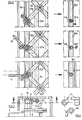
- Fig. 1 the control scheme is shown using three superposed levers 1a, 1b, 1c. While the chain wheels 2a, 2b, 2c are firmly connected to the levers 1a, 1b, 1c, the chain wheels 5a, 5b, 5c can be rotated relative to the lever and to the fixed chain wheel. The angle of rotation is limited by control stops 3a, 3b, 3c which are arranged on the fixed chain wheels 2a, 2b, 2c and which engage in control grooves 6a, 6b, 6c of the loose chain wheels 5a, 5b, 5c.
- Deflection wheels 15a, b are also located between the levers, which are connected to timing chains 29, 30 with the associated loose and fixed chain wheels 2, 5.
- Fig. 2 now shows the positioning of the individual levers 1a, 1b, 1c within the stacking column. This is done via scissor links 9a, b, c; 10a, b, c, which slide in guide grooves 16.
- the associated position of the stop profile is shown. In the rest position, the stop profile 21a is located below the bearing pin 4a. It is supported against the guide groove 16a. In the receiving position, the stop profile 21b is approximately at the same level with the bearing pin 4b. In the working position, the stop profile 21c is supported against the guide groove 16c, so that the control parts are relieved of the torque.
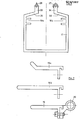
- Fig. 4 shows two views of the stop profile 21 and the support profile 20 from the lever 1. It can be seen that the octagonal design of the bore guarantees a torsion-proof attachment of the support profile and the stop profile on the bearing pin 4.
- All other parts located on the bearing pin 7b correspond to the structure already explained above on the bearing pin 4a.
- the deflection roller 15 is also via a timing chain with the loose sprocket 5b connected on the shaft 4b.
- Other parts such as the bearing bush, spacer and retaining rings correspond to the previously described structure of the shafts 4a and 7b.
- the scissor links 8d, the support profile 20 and the stop profile 39 can also be seen on the shaft 4c.
- Fig. 6 shows a cross section through the support profile 17 with guide grooves 16a, 16b and two angular webs, each fastened to the open side of the profile with an angle end 31, 32 'and in each case in the other outwardly directed leg end 33, 34 a passage opening for form the lever 1.
- the leg ends 33, 34 can additionally be equipped with an edge protector 27, 28.
- the support arm 19 is detachably connected to the support profile 20 via a screw, in such a way that a change of the support arm 19 is possible from the passage opening of the support profile 17.
- the groove 16b arranged in the carrier profile 17 serves as a stop for the stop profile 39.
- the pivoting movement of the lever 1 is made possible via chain wheels 40 and deflection rollers 15.
- the lever 1b in the receiving position is pivoted into its rest position by pulling up the stored goods.
- spring force e.g. caused by torsion springs.
- F ig. 10 shows a multi-part stacking column, consisting of the base column 24 and the attachment 25. Parallel to the guide groove 16, locking profiles 22a, 22b can be seen which have an eccentric 23.
- Fig. 11 the multi-part stacking column is shown in the assembled state. A rotationally secure connection between the locking profiles 22a, b is ensured by the plug-on axis 26.
- FIG. 12 shows a partial cross section through the base column 24 with the locking profile 22 and the eccentric 23.
- the eccentric instead of the eccentric, other types of locking, non-positive or positive can be used.
- the levers 1, the carrier profile 17, the cover 18, the leg ends 31, 33, 34 and the tension screw 13 with the tension nut 14 can be seen. These serve to relieve strain on the scissor links.
- the individual parts of the device according to the invention can be produced from metal, in particular aluminum, but also from plastic and combinations of plastic-metal. When using aluminum, extruded profiles and levers are preferably used.
Landscapes
- Engineering & Computer Science (AREA)
- Mechanical Engineering (AREA)
- Warehouses Or Storage Devices (AREA)
- Conveying Record Carriers (AREA)
- Automatic Tape Cassette Changers (AREA)
- Vending Machines For Individual Products (AREA)
Priority Applications (1)
| Application Number | Priority Date | Filing Date | Title |
|---|---|---|---|
| AT86103591T ATE43553T1 (de) | 1985-04-12 | 1986-03-17 | Vorrichtung zum lagern von teilen im abstand voneinander insbesondere zum lagern von blechen oder blechformteilen. |
Applications Claiming Priority (2)
| Application Number | Priority Date | Filing Date | Title |
|---|---|---|---|
| DE3513160 | 1985-04-12 | ||
| DE19853513160 DE3513160A1 (de) | 1985-04-12 | 1985-04-12 | Vorrichtung zum lagern von teilen im abstand uebereinander, insbesondere zum lagern von blechen oder blechformteilen |
Publications (3)
| Publication Number | Publication Date |
|---|---|
| EP0197367A2 true EP0197367A2 (fr) | 1986-10-15 |
| EP0197367A3 EP0197367A3 (en) | 1987-06-03 |
| EP0197367B1 EP0197367B1 (fr) | 1989-05-31 |
Family
ID=6267848
Family Applications (1)
| Application Number | Title | Priority Date | Filing Date |
|---|---|---|---|
| EP86103591A Expired EP0197367B1 (fr) | 1985-04-12 | 1986-03-17 | Dispositif pour le stockage d'objets de façon indépendante, par exemple des toiles |
Country Status (3)
| Country | Link |
|---|---|
| EP (1) | EP0197367B1 (fr) |
| AT (1) | ATE43553T1 (fr) |
| DE (2) | DE3513160A1 (fr) |
Family Cites Families (3)
| Publication number | Priority date | Publication date | Assignee | Title |
|---|---|---|---|---|
| US3231103A (en) * | 1962-09-10 | 1966-01-25 | Fruehauf Corp | Container stacking system |
| FR2086216B3 (fr) * | 1970-04-21 | 1974-02-15 | Grenzebach Rudolf | |
| DE2930053C2 (de) * | 1979-07-25 | 1989-06-29 | Bayerische Motoren Werke AG, 8000 München | Vorrichtung zum Lagern von Teilen annähernd gleicher Form und Größe im Abstand übereinander, insbesondere zum Lagern von Blechen oder Blechformteilen |
-
1985
- 1985-04-12 DE DE19853513160 patent/DE3513160A1/de not_active Withdrawn
-
1986
- 1986-03-17 AT AT86103591T patent/ATE43553T1/de not_active IP Right Cessation
- 1986-03-17 DE DE8686103591T patent/DE3663648D1/de not_active Expired
- 1986-03-17 EP EP86103591A patent/EP0197367B1/fr not_active Expired
Also Published As
| Publication number | Publication date |
|---|---|
| EP0197367A3 (en) | 1987-06-03 |
| EP0197367B1 (fr) | 1989-05-31 |
| ATE43553T1 (de) | 1989-06-15 |
| DE3663648D1 (en) | 1989-07-06 |
| DE3513160A1 (de) | 1986-10-16 |
Similar Documents
| Publication | Publication Date | Title |
|---|---|---|
| EP0670123A1 (fr) | Table de travail à hauteur modifiable | |
| DE1611809C3 (de) | Gewichtsausgleichsvorrichtung für einen höhenverstellbaren Zeichentisch | |
| DE2159534A1 (de) | Einrichtung zum Auflagern und Abgeben gestapelter Gegenstände, die sich stets selbsttätig auf die richtige Höhe einstellt | |
| DE3014325C2 (de) | Vorrichtung zum Verriegeln einer Arbeitsplatte o.dgl. in unterschiedlichen Neigungsstellungen | |
| DE19963057C1 (de) | Tenderlift zur Anbringung an einem Wasserfahrzeug | |
| DE3916594A1 (de) | Tisch mit einstellbarer woelbung fuer abkantpressen, richtplatten und aehnliche vorrichtungen | |
| DE3828469A1 (de) | Legebarrenlagerung fuer kettenwirkmaschinen | |
| DE69730077T2 (de) | Anlage mit beweglichen Klinken mit Rückstell-Unterstützung zum Lagern in allen Stellungen, insbesondere für im wesentlichen flache Gegenstände mit relativ grossen Abmessungen | |
| DE19644010B4 (de) | Fördervorrichtung | |
| EP0197367B1 (fr) | Dispositif pour le stockage d'objets de façon indépendante, par exemple des toiles | |
| EP0070422A2 (fr) | Table de travail, en particulier bureau | |
| DE2529430C2 (de) | Demonstrationstafel (Flip-chart) | |
| EP1475493A2 (fr) | Ajustement en hauteur de plateau de podium | |
| DE102018119744A1 (de) | Transportwagen | |
| CH693161A5 (de) | Ausziehvorrichtung eines Hochschrankes. | |
| EP0042465B1 (fr) | Dispositif de transport pour matériau de construction en travaux de couvreur | |
| DE2216438A1 (de) | Fotografisches stativ | |
| DE3037375A1 (de) | Hoehenverstellbarer objekttraeger | |
| DE3533991C2 (fr) | ||
| EP0422254B1 (fr) | Plafond filtrant spécialement pour chambres de pulvérisation | |
| WO1997039658A1 (fr) | Repose-pied reglable en hauteur, notamment pour tables de montage | |
| DE69600296T2 (de) | Anordnung zur Blattzuführung von einem Blattbündel | |
| DE9013505U1 (de) | Sicherungselement zur Sicherung einer an eine ortsfeste Dachrinne o.dgl. angelehnten Leiter | |
| DE9310090U1 (de) | Freitragendes Schiebetor | |
| DE2815845A1 (de) | Vorrichtung zum leichteren loesen festsitzender radschrauben und -muttern |
Legal Events
| Date | Code | Title | Description |
|---|---|---|---|
| PUAI | Public reference made under article 153(3) epc to a published international application that has entered the european phase |
Free format text: ORIGINAL CODE: 0009012 |
|
| AK | Designated contracting states |
Kind code of ref document: A2 Designated state(s): AT BE CH DE FR GB IT LI LU NL SE |
|
| PUAL | Search report despatched |
Free format text: ORIGINAL CODE: 0009013 |
|
| AK | Designated contracting states |
Kind code of ref document: A3 Designated state(s): AT BE CH DE FR GB IT LI LU NL SE |
|
| 17P | Request for examination filed |
Effective date: 19870731 |
|
| 17Q | First examination report despatched |
Effective date: 19871103 |
|
| GRAA | (expected) grant |
Free format text: ORIGINAL CODE: 0009210 |
|
| AK | Designated contracting states |
Kind code of ref document: B1 Designated state(s): AT BE CH DE FR GB IT LI LU NL SE |
|
| REF | Corresponds to: |
Ref document number: 43553 Country of ref document: AT Date of ref document: 19890615 Kind code of ref document: T |
|
| ITF | It: translation for a ep patent filed | ||
| REF | Corresponds to: |
Ref document number: 3663648 Country of ref document: DE Date of ref document: 19890706 |
|
| GBT | Gb: translation of ep patent filed (gb section 77(6)(a)/1977) | ||
| ET | Fr: translation filed | ||
| PLBE | No opposition filed within time limit |
Free format text: ORIGINAL CODE: 0009261 |
|
| STAA | Information on the status of an ep patent application or granted ep patent |
Free format text: STATUS: NO OPPOSITION FILED WITHIN TIME LIMIT |
|
| 26N | No opposition filed | ||
| PGFP | Annual fee paid to national office [announced via postgrant information from national office to epo] |
Ref country code: GB Payment date: 19910225 Year of fee payment: 6 |
|
| PGFP | Annual fee paid to national office [announced via postgrant information from national office to epo] |
Ref country code: AT Payment date: 19910228 Year of fee payment: 6 |
|
| PGFP | Annual fee paid to national office [announced via postgrant information from national office to epo] |
Ref country code: FR Payment date: 19910307 Year of fee payment: 6 |
|
| PGFP | Annual fee paid to national office [announced via postgrant information from national office to epo] |
Ref country code: BE Payment date: 19910311 Year of fee payment: 6 |
|
| PGFP | Annual fee paid to national office [announced via postgrant information from national office to epo] |
Ref country code: SE Payment date: 19910318 Year of fee payment: 6 Ref country code: LU Payment date: 19910318 Year of fee payment: 6 |
|
| ITTA | It: last paid annual fee | ||
| PGFP | Annual fee paid to national office [announced via postgrant information from national office to epo] |
Ref country code: NL Payment date: 19910331 Year of fee payment: 6 |
|
| PGFP | Annual fee paid to national office [announced via postgrant information from national office to epo] |
Ref country code: DE Payment date: 19910413 Year of fee payment: 6 |
|
| PGFP | Annual fee paid to national office [announced via postgrant information from national office to epo] |
Ref country code: CH Payment date: 19910415 Year of fee payment: 6 |
|
| EPTA | Lu: last paid annual fee | ||
| PG25 | Lapsed in a contracting state [announced via postgrant information from national office to epo] |
Ref country code: LU Free format text: LAPSE BECAUSE OF NON-PAYMENT OF DUE FEES Effective date: 19920317 Ref country code: GB Effective date: 19920317 Ref country code: AT Effective date: 19920317 |
|
| PG25 | Lapsed in a contracting state [announced via postgrant information from national office to epo] |
Ref country code: SE Effective date: 19920318 |
|
| PG25 | Lapsed in a contracting state [announced via postgrant information from national office to epo] |
Ref country code: LI Effective date: 19920331 Ref country code: CH Effective date: 19920331 Ref country code: BE Effective date: 19920331 |
|
| BERE | Be: lapsed |
Owner name: VEREINIGTE ALUMINIUM-WERKE A.G. Effective date: 19920331 |
|
| PG25 | Lapsed in a contracting state [announced via postgrant information from national office to epo] |
Ref country code: NL Effective date: 19921001 |
|
| GBPC | Gb: european patent ceased through non-payment of renewal fee | ||
| NLV4 | Nl: lapsed or anulled due to non-payment of the annual fee | ||
| PG25 | Lapsed in a contracting state [announced via postgrant information from national office to epo] |
Ref country code: FR Effective date: 19921130 |
|
| REG | Reference to a national code |
Ref country code: CH Ref legal event code: PL |
|
| PG25 | Lapsed in a contracting state [announced via postgrant information from national office to epo] |
Ref country code: DE Effective date: 19921201 |
|
| REG | Reference to a national code |
Ref country code: FR Ref legal event code: ST |
|
| EUG | Se: european patent has lapsed |
Ref document number: 86103591.3 Effective date: 19921005 |
|
| PG25 | Lapsed in a contracting state [announced via postgrant information from national office to epo] |
Ref country code: IT Free format text: LAPSE BECAUSE OF NON-PAYMENT OF DUE FEES;WARNING: LAPSES OF ITALIAN PATENTS WITH EFFECTIVE DATE BEFORE 2007 MAY HAVE OCCURRED AT ANY TIME BEFORE 2007. THE CORRECT EFFECTIVE DATE MAY BE DIFFERENT FROM THE ONE RECORDED. Effective date: 20050317 |