EP0196887A2 - Vermi-Kompostierungssystem - Google Patents
Vermi-Kompostierungssystem Download PDFInfo
- Publication number
- EP0196887A2 EP0196887A2 EP86302302A EP86302302A EP0196887A2 EP 0196887 A2 EP0196887 A2 EP 0196887A2 EP 86302302 A EP86302302 A EP 86302302A EP 86302302 A EP86302302 A EP 86302302A EP 0196887 A2 EP0196887 A2 EP 0196887A2
- Authority
- EP
- European Patent Office
- Prior art keywords
- container
- floor
- charge
- waste
- elongate member
- Prior art date
- Legal status (The legal status is an assumption and is not a legal conclusion. Google has not performed a legal analysis and makes no representation as to the accuracy of the status listed.)
- Withdrawn
Links
- 238000009265 vermicomposting Methods 0.000 title claims description 16
- 239000002699 waste material Substances 0.000 claims description 48
- 239000000463 material Substances 0.000 claims description 35
- 238000010438 heat treatment Methods 0.000 claims description 7
- 239000012190 activator Substances 0.000 claims description 4
- 238000013461 design Methods 0.000 abstract description 11
- 238000009264 composting Methods 0.000 abstract description 6
- 239000002361 compost Substances 0.000 abstract description 3
- 238000009368 vermiculture Methods 0.000 abstract description 3
- 208000028659 discharge Diseases 0.000 description 22
- 229910000831 Steel Inorganic materials 0.000 description 9
- 239000010959 steel Substances 0.000 description 9
- 238000010276 construction Methods 0.000 description 5
- XLYOFNOQVPJJNP-UHFFFAOYSA-N water Substances O XLYOFNOQVPJJNP-UHFFFAOYSA-N 0.000 description 5
- 230000015556 catabolic process Effects 0.000 description 4
- 241001465754 Metazoa Species 0.000 description 3
- 230000000712 assembly Effects 0.000 description 3
- 238000000429 assembly Methods 0.000 description 3
- 230000000694 effects Effects 0.000 description 3
- 239000002689 soil Substances 0.000 description 3
- 239000007787 solid Substances 0.000 description 3
- 230000009286 beneficial effect Effects 0.000 description 2
- 238000007599 discharging Methods 0.000 description 2
- 238000006073 displacement reaction Methods 0.000 description 2
- 238000001704 evaporation Methods 0.000 description 2
- 230000008020 evaporation Effects 0.000 description 2
- 210000003608 fece Anatomy 0.000 description 2
- 239000010871 livestock manure Substances 0.000 description 2
- 230000014759 maintenance of location Effects 0.000 description 2
- 238000004519 manufacturing process Methods 0.000 description 2
- 230000004048 modification Effects 0.000 description 2
- 238000012986 modification Methods 0.000 description 2
- 238000012545 processing Methods 0.000 description 2
- 238000010008 shearing Methods 0.000 description 2
- 241000283690 Bos taurus Species 0.000 description 1
- 241000282887 Suidae Species 0.000 description 1
- 230000009471 action Effects 0.000 description 1
- 238000005273 aeration Methods 0.000 description 1
- 239000003674 animal food additive Substances 0.000 description 1
- 238000006731 degradation reaction Methods 0.000 description 1
- 238000001035 drying Methods 0.000 description 1
- 230000006872 improvement Effects 0.000 description 1
- 238000009413 insulation Methods 0.000 description 1
- 230000007246 mechanism Effects 0.000 description 1
- 239000002184 metal Substances 0.000 description 1
- 238000000034 method Methods 0.000 description 1
- 230000000813 microbial effect Effects 0.000 description 1
- 238000002156 mixing Methods 0.000 description 1
- 239000010815 organic waste Substances 0.000 description 1
- 238000013021 overheating Methods 0.000 description 1
- 239000002245 particle Substances 0.000 description 1
- 239000011236 particulate material Substances 0.000 description 1
- 238000009372 pisciculture Methods 0.000 description 1
- 244000144977 poultry Species 0.000 description 1
- 230000008569 process Effects 0.000 description 1
- 230000000750 progressive effect Effects 0.000 description 1
- 238000011084 recovery Methods 0.000 description 1
- 230000000717 retained effect Effects 0.000 description 1
- 230000002441 reversible effect Effects 0.000 description 1
- 238000000926 separation method Methods 0.000 description 1
- 239000010802 sludge Substances 0.000 description 1
- 239000002002 slurry Substances 0.000 description 1
- 238000003756 stirring Methods 0.000 description 1
- 239000010902 straw Substances 0.000 description 1
- 230000003442 weekly effect Effects 0.000 description 1
Images


Classifications
-
- C—CHEMISTRY; METALLURGY
- C05—FERTILISERS; MANUFACTURE THEREOF
- C05F—ORGANIC FERTILISERS NOT COVERED BY SUBCLASSES C05B, C05C, e.g. FERTILISERS FROM WASTE OR REFUSE
- C05F17/00—Preparation of fertilisers characterised by biological or biochemical treatment steps, e.g. composting or fermentation
- C05F17/05—Treatments involving invertebrates, e.g. worms, flies or maggots
-
- Y—GENERAL TAGGING OF NEW TECHNOLOGICAL DEVELOPMENTS; GENERAL TAGGING OF CROSS-SECTIONAL TECHNOLOGIES SPANNING OVER SEVERAL SECTIONS OF THE IPC; TECHNICAL SUBJECTS COVERED BY FORMER USPC CROSS-REFERENCE ART COLLECTIONS [XRACs] AND DIGESTS
- Y02—TECHNOLOGIES OR APPLICATIONS FOR MITIGATION OR ADAPTATION AGAINST CLIMATE CHANGE
- Y02P—CLIMATE CHANGE MITIGATION TECHNOLOGIES IN THE PRODUCTION OR PROCESSING OF GOODS
- Y02P20/00—Technologies relating to chemical industry
- Y02P20/141—Feedstock
- Y02P20/145—Feedstock the feedstock being materials of biological origin
-
- Y—GENERAL TAGGING OF NEW TECHNOLOGICAL DEVELOPMENTS; GENERAL TAGGING OF CROSS-SECTIONAL TECHNOLOGIES SPANNING OVER SEVERAL SECTIONS OF THE IPC; TECHNICAL SUBJECTS COVERED BY FORMER USPC CROSS-REFERENCE ART COLLECTIONS [XRACs] AND DIGESTS
- Y02—TECHNOLOGIES OR APPLICATIONS FOR MITIGATION OR ADAPTATION AGAINST CLIMATE CHANGE
- Y02W—CLIMATE CHANGE MITIGATION TECHNOLOGIES RELATED TO WASTEWATER TREATMENT OR WASTE MANAGEMENT
- Y02W30/00—Technologies for solid waste management
- Y02W30/40—Bio-organic fraction processing; Production of fertilisers from the organic fraction of waste or refuse
Definitions
- the present invention relates to a solids discharge device and in particular, but not exclusively, to one for discharging friable and/or particulate material from a container e.g. as part of a vermicomposting system for commercial scale vermiculture.
- the aim of vermicomposting is the improvement of wastes into a useful or marketable product
- the production of worms is another result of the process as these have a high protein content and when separated from the processed waste, can be used as a feed additive, e.g. for fish farming, or for pigs or poultry.
- Machines which use one or more augers for discharging compost from a compost bin but such arrangements are expensive for large-area bins and also less than satisfactory in a vermicomposting system, for example, where, ideally, worked material should be extracted from the lowermost layers of the charge with only negligible disturbance of the upper worm-containing layers of material.
- Commonly used equipment comprises a hopper with vertical or near-vertical sides astride a very heavy duty belt conveyor of the roller bed type, with massive drive and idler drums powered by a very high torque variable speed drive. Flow rate is determined by a combination of belt speed and restriction of the hopper front aperture. Flow of material through the aperture requires massive shearing forces to be generated.
- An object of the present invention is to provide a discharge device by which the disadvantages outlined above for existing systems may be avoided or at least significantly reduced.
- Another object of the patent invention is to provide a continuous vermicomposting system rather than the batch systems referred to above.
- a discharge device e.g. for a friable and/or paniculate material, comprises a container having an apertured floor, one or more material-displacing members engaging with or lying adjacent to the upper surface of the floor, and drive means for moving the one or more members bodily across the floor thereby to urge material in the container downwardly through the apertures in the floor.
- the container is square or rectangular when viewed in plan, the one or more material-displacing members comprising an elongate member lying parallel to the length or width dimension of the container, and the drive means is operative to move the elongate member in directions parallel to the other of these two dimensions.
- the elongate member spans or substantially spans the container.
- the elongate member has a rectangular or domed cross-section.
- the elongate member inclines upwardly at each end.
- the elongate member includes one or more vertical tines.
- the or each tine comprises a flat e.g. triangular, vertical projection having its main plane aligned with the direction of movement of the elongate member through the container.
- the or each tine is apertured and the device includes aerating means for supplying air to these apertures.
- the aerating means comprises an air-supply tube through which air from a pump is provided to the tines e.g. via an air-supply reel.
- the elongate member referred to above comprises a first such member and the one or more material-displacing members includes a second elongate member arranged at right angles to the first member.
- the first and second material-displacing members are arranged so as in plan view to provide a simple cruciform structure, preferably unbraced.
- the overall length of the second elongate member is not less than about two thirds the overall length of the first elongate member.
- the second elongate member inclines upwardly at each end.
- the drive means comprises a winch or chain and sprocket system e.g. with the cable or chain, as the case may be, attached to either end of the second elongate member (when present).
- the drive means may comprise one or more rams or other linear activators.
- the invention also includes a vermicomposting system incorporating a device according to the present invention and in particular, but not exclusively, a continuous vermicomposting apparatus comprising a container for a charge of worm-containing waste material, feed means for adding further amounts of said material to the top of the charge and discharge means according to the present invention for removing from the bottom of the charge quantities of the material processed by the worms in the container.
- the floor of the container is apertured and the discharge means operates by forcing worm-processed material through the apertures in the container floor.
- the discharge means comprises an elongate member adapted to traverse the upper surface of the container floor laterally.
- the floor of the container may comprise a plurality of longitudinally finned or otherwise shaped elements of non-circular cross-section co-operating to provide a floor to the container and rotatable about their longitudinal axes to encourage material from the container to pass through the container floor.
- the elements are spaced apart to provide the container with an apertured floor and rotation of the elements about their axes encourages material to pass through the apertures in the container floor.
- the apparatus includes drive means operative to rotate the elements in a to and fro motion.
- the apparatus includes fan means operative to provide a flow of aerating and/or heating air to the undersurface of the charge.
- the apparatus includes means for supplying supplementary heating to the middle and/or upper layers of the charge.
- the apparatus includes feed means operative to break up lumps in a supply of unprocessed material before loading it onto the upper surface of the charge.
- the apparatus includes means for watering the upper layers of the charge.
- the apparatus includes enclosure means operative to prevent overwetting of the charge by rain when the apparatus is installed in the open air and to discourage the excessive evaporation of water from the charge in dry conditions.
- the invention further includes a bedding system for animals, or a feed hopper, when incorporating a discharge device according to the present invention.
- a continuous vermicomposting apparatus comprises a container for a charge of worm-containing waste material, feed means for adding further amounts of said material to the top of the charge and discharge means according to the present invention for removing from the bottom of the charge quantities of the material processed by the worms in the container.
- Figures 1 to 3 show three alternative designs of apertured floor for the container of a continuous vermicomposting system, namely a grid 10 (Figure 1) a mesh 12 ( Figure 2), and a slanting bar construction 14 ( Figure 3).
- the spacing between adjacent floor members would typically be of a value of from 75 mm up to 200 mm, say.
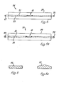
- Figure 4 shows a simple form of breaker bar unit 16 comprising two elongate members 18, 19 arranged in a simple unbraced cruciform construction.
- Lugs 21, 22 extending upwardly from member 18 allow the construction to be pulled in a direction parallel to this member across the floor of the container.
- the cross-member 19 is dimensioned so as to span or substantially span the container and the length of member 18 is preferably not less than about two thirds of the length of member 19.
- the separation I of each lug 21, 22 from the adjacent edge of cross-member 19 was designed to be not more than one third the length w of the member 18.
- both members 18, 19 incline upwardly at either end e.g. at about 30° to the horizontal.
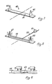
- Figures 5 and 5a show alternative designs of drive system for use in a layer composting system of, say, 50 to 75 square metres (corresponding respectively to containers of 20 metres to 30 metres length, say).
- a simple hydraulic ram or similar linear activator may be employed e.g. as shown in the arrangement of Figure 3 to be described hereinafter.
- a modified ram or linear activator system may be used to drive intermediate size soil-displacement units, such as shown, for example, in Figures 8 to 10 still to be described in detail below.
- thiks latter type of drive system will be hereinafter described with reference to Figure 16.
- the drive system 24 comprises, in essence, a winch 26 and idler pulley 27, one at either end of the container 29.
- a steel cable 31 attached to lug 21 passes around the winch 26 and then underneath the container floor 33 and back around the idler pulley 27 for attachment to the second lug 22.
- the steel cable 31 is replaced by a chain 37 and the winch 26 and idler pulley 27 are replaced by a sprocket drive 39, 40.
- both rotary supports can be driven.
- a force of around 3000-400ON per metre width w of the cross-member 19 will be required to draw the soil-displacement unit horizontally across the perforated floor of the container and discharge material therethrough without becoming obstructed by any small stones etc. present in the soil.
- Waste rests on the perforated floor of the container because of its characteristic tendency to bridge, and the size of the perforations is chosen as the minimum required to ensure the support of the material. On the initial loading, inevitably some material will pass straight through.
- the breaker-bar unit In operation, when drawn over the container floor beneath the waste layers in a vermicomposting system, the breaker-bar unit will set up shearing of waste along a line forward of itself. The waste lying below this line is disturbed and its movement results in a localised breakdown of the bridging by which it is supported on the container floor, hence the terminology 'breaker' bar. Waste above the line of shear remains substantially undisturbed so that worm activity is unaffected. However, there is a 'heaving' effect as the bar passes through and this causes some fissuring of settled waste which is beneficial for maintaining aerobicity of the waste. Vetical leading edges of the bar are essential but the bar may be flat topped ( Figure 6) or crowned ( Figure 6 a) to give more heaving. Because the bar operates in both directions it must always be of uniform cross-section.
- FIG 7 shows a breaker bar 42 particularly suited for this different environment insofar as vertical triangular tines 44, 45 are now provided to entrain air into the waste.
- hollow tines 47, 48 with internal air feed are used to give localised forced aeration on every breaker pass as shown in Figure 8 where reference numerals 50, 51 respectively indicate a tube and air-supply reel for supplying air to the tines.
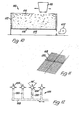
- Figure 9 illustrates another possible use for the equipment.
- accumulating layers of bedding make the use of fixed height feeders and waterers impossible.
- a breaker bar 53 of massive construction running on a large grid floor 55 e.g. 200 x 200 mm could break out the lower layers of farmyard manure leaving stock on a pleasant insulating and well drained layer of the manure.
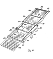
- a continuous vermicomposting apparatus 110 comprises a container 112 for a charge of worm-containing organic farmyard waste 114.
- the organic waste is loaded or fed to the top of the container in thin layers (typically 20 mm) by a gantry-mounted manure-spreading trolley 116 extending across the full width of the container and able to traverse it from one end to the other.
- the trolley also serves to break up any lumps initially present in the material.
- the container 112 is loaded from the discharge floor of a reception vessel e.g. in the form of a travelling hopper, positioned over the top of the container.
- Reference numeral 118 indicates the floor of the container. This is preferably of an open mesh construction as best seen from Figure 11. Typically, for example, the floor might be provided by a 50 mm square or 75 mm square galvanised steel mesh through which processed waste can be discharged by a chain-drawn breaker bar 20 (shown only in Figure 11).
- the bar 120 extends across the width dimension of the container floor and, in operation, winch units (not shown) will move it transversely from end to end of the floor, typically at about 1000 cm per minute.
- the breaker bar might typically be formed from flat steel bar of 50 mm x 6 mm cross-section.
- the corresponding bar cross-section might typically be 40 mm x 12 mm, say.
- closely spaced parallel bars may be used instead if desired.
- the container floor 1.18 must be raised above ground level to provide a collection space 119 for material forced through the mesh by bar 120.
- at least the lower layers of material in the container can be aerated, and optionally also dried to some extent, by a fan 122 adapted to provide a blast of cold or hot air beneath the floor 118. This will also be effective in drying out previously discharged matter prior to its removal from beneath the container.
- Supplementary heating is also possible if desired, e.g. by electric cables (not shown) mounted at a mid or upper position in the container. Conveniently, these heating cables will be wound around tensioned steel support cables passing from side to side and/or end to end of the container.
- the apparatus is completed by thermal insulation and an enclosure (not shown) to prevent overwetting when the container is installed in the open air.
- the presence of the enclosure will also discourage excessive evaporation of water from the waste in dry weather though a spinkler system (not shown) is also preferably provided as a safeguard to water the upper layers of waste 114 should conditions require. In the event of excess water being provided, this can freely drain through the floor mesh of the container.
- the container 112 In operation of the apparatus, the container 112 is loaded with worm-containing waste as described and the temperature, aerobicity and dampness of the material waste is adjusted if required for optimum conditions.
- the high population of worms within the container (typically 3 to 6 Kg of worms per square metre of material) will continually refine the waste, breaking it down to a smaller particle size.
- the worms will continually move upward to new layers of waste as the previous layers become exhausted. Discharge of processed waste through the floor of the container takes place at substantially similar intervals to those at which new waste is added to the top, maintaining a fixed amount of continually renewed waste for processing in the container.
- the processed waste will be substantially worm-free and can be discharged through the floor as already discussed for recovery by scraper, conveyor, skip or other suitable means.
- the aim is always to maintain a high population of worms and achieve maximum throughput of waste.
- a typical weekly output of vermicompost when using separated solids waste derived from cattle slurry is about 0.08 cubic meters per square metre of floor space of the apparatus.
- Figure 12 shows an alternative design of discharge mechanism in which the container floor consists of finned metal square-section elements 124 spanning the base of the container and able to rotate clockwise and anti-clockwise (e.g. through 90 0 ) to obtain through-floor discharge of the contents of the container.
- the elements 124 will be steel tubes or rolled hollow sections to which the fins have been welded.
- the optimum centre spacings of elements 124 will depend on the bridging properties of the material to be discharged but a centre spacing of around 150 mm would be typical.
- the fins may not be necessary for effective discharge to occur, the fins are nevertheless found to result in a more positive discharge and hence their presence is to be preferred. In the illustrated embodiment, the fins might project by about 25 mm, say, from the upper three corners of the square-section elements 124.
- Rotation of the sections 124 in a to and fro motion is by an actuator device 126 in which a common linear actuator 130 is linked to the various sections by a,series of crank arms.
- apparatus according to the present invention could also find application in the discharge of materials such as municipal sludge or materials presenting severe bridging or other flow problems.
- FIG. T3 One such apparatus is shown in Figure T3 and consists of a hopper 140 with vertical sides and a floor 142 constructed of a steel grid or mesh. The optimum dimensions of the hopper are determined by the type of material to be fed.
- a framework 144 supporting a number of members 146 which span the width of the hopper.
- Members 146 comprise breaker bars of any of the designs illustrated in the previous Figures and they serve to cause localised breakdown of the bridging effect by which the material rests on the floor 142. To achieve this end, the members 146 are caused to reciprocate slowly (say, 100 mm/sec) by, for example, a variable-speed electric screw type linear actuator 148. This causes a controlled and even discharge over the whole hopper floor area and has the beneficial effect of breaking down lumps and structures within the material.
- a simple light duty belt conveyor 150 to collect the discharge and transport it to a delivery point.
- This conveyor is lightly loaded and its speed is not critical as it does not serve as a metering device. Metering is done by the discharge floor 142 and flow rate is adjusted by the rate at which the linear actuator 148 reciprocates the breaker bar members 146.
- the breaker bars form part of a motor-driven chain loop conveyor but this detracts from the simplicity and serviceability of a simple reciprocating breaker bar framework.
- a rotary (e.g. propeller) breaker is driven by a high torque motor in a suitably proportioned cylindrical hopper having a perforated circular discharge floor.
- FIGS 14 and 15 show an underfloor scaper 160 for collecting waste 162 which has been forced through the apertured floor (not shown) of the container by the scaper bars to accumulate on collecting surface 164.
- the scraper 160 comprises a frame 166 running in U-channel tracks 168, 169 and supporting a number of pivoted scraper blade assemblies 171 which lift on rearward movement of the frame 166 wherever they contact a pile of waste 162 on surface 164. In their forward movement, however, pivoting of the blade assemblies is prevented by contact between the lower surface of the frame 166 and abutment plates 173 mounted on the scapers.
- the structure of the hinges (174) is such that they will be unaffected by falling waste (see, e.g. Figure 15).
- a double-acting hydraulic ram 175 with auto-shuttle valve acts on one of the cross-members of the frame 166 to drive the frame in a reciprocatory motion under the container floor.
- the scraper assemblies are held against rotation by the action of plates 173 and act to deliver waste in the direction shown by the arrow in Figure 14.
- the blades are free to pivot and ride over the accumulated waste as shown in the dotted line position on the left of this Figure.
- this illustrates a breaker drive system comprising two pairs of double-acting rams 180, 181 arranged in opposition between ground anchors 183, 184 and transverse cross-bars 185, 186 of the breaker frame 188 so as to maintain the latter in tension at all times. It will be appreciated that the leading rams are extending with full piston-face forces.
- the drive system of Figure 16 is intended principally as an alternative to the winched arrangements of the earlier Figures for containers up to 10 metres length, say, beyond which the power requiremens may become excessive.
- the breaker bars 190 are flat steel bars of 2.5 metres width and 40 x . 12 mm cross-section.
- a typical ram stroke 191 and breaker bar centre-to-centre distance would be 2.5 metres and the steel mesh floor 192 of the container would typically have an aperture size of 75 x 75 mm, say.
Landscapes
- Chemical & Material Sciences (AREA)
- Life Sciences & Earth Sciences (AREA)
- Health & Medical Sciences (AREA)
- Chemical Kinetics & Catalysis (AREA)
- Tropical Medicine & Parasitology (AREA)
- Engineering & Computer Science (AREA)
- Biochemistry (AREA)
- Biotechnology (AREA)
- Insects & Arthropods (AREA)
- General Chemical & Material Sciences (AREA)
- Microbiology (AREA)
- Molecular Biology (AREA)
- Organic Chemistry (AREA)
- Processing Of Solid Wastes (AREA)
- Fertilizers (AREA)
- Greenhouses (AREA)
Applications Claiming Priority (4)
| Application Number | Priority Date | Filing Date | Title |
|---|---|---|---|
| GB858508264A GB8508264D0 (en) | 1985-03-29 | 1985-03-29 | Vermicomposting system |
| GB8508264 | 1985-03-29 | ||
| GB8523691 | 1985-09-25 | ||
| GB858523691A GB8523691D0 (en) | 1985-09-25 | 1985-09-25 | Solids discharge device |
Publications (2)
| Publication Number | Publication Date |
|---|---|
| EP0196887A2 true EP0196887A2 (de) | 1986-10-08 |
| EP0196887A3 EP0196887A3 (de) | 1987-05-27 |
Family
ID=26289062
Family Applications (1)
| Application Number | Title | Priority Date | Filing Date |
|---|---|---|---|
| EP19860302302 Withdrawn EP0196887A3 (de) | 1985-03-29 | 1986-03-27 | Vermi-Kompostierungssystem |
Country Status (2)
| Country | Link |
|---|---|
| EP (1) | EP0196887A3 (de) |
| GB (1) | GB2174079B (de) |
Cited By (15)
| Publication number | Priority date | Publication date | Assignee | Title |
|---|---|---|---|---|
| US5484362A (en) * | 1989-06-19 | 1996-01-16 | Life Fitness | Exercise treadmill |
| GB2326638A (en) * | 1997-06-27 | 1998-12-30 | Simon Taylor | Conversion of waste material by worms |
| WO1999051545A1 (en) * | 1998-04-06 | 1999-10-14 | Vermitech Pty. Ltd. | Treatment of waste materials |
| EP0887328A3 (de) * | 1997-06-27 | 2000-01-05 | Simon Taylor | Umwandeln von Abfallstoffen durch Einsatz von Erdwürmern |
| WO2002020429A1 (en) * | 2000-09-05 | 2002-03-14 | Tryton Group Pty Ltd | Method and apparatus for the treatment of waste |
| US6436008B1 (en) | 1989-06-19 | 2002-08-20 | Brunswick Corporation | Exercise treadmill |
| WO2004035509A1 (en) * | 2002-10-17 | 2004-04-29 | Vermitech Limited | Apparatus for use in vermiculture |
| US7018831B2 (en) * | 2001-09-26 | 2006-03-28 | Biosystem Solutions, Inc. | Composting apparatus and method |
| FR2913007A1 (fr) * | 2007-02-23 | 2008-08-29 | Centre Nat Machinisme Agricole | Dispositif d'extraction de compost au travers d'une grille de soutenement |
| FR2928359A1 (fr) * | 2008-03-07 | 2009-09-11 | Ct Nat De Machinisme Agricole | "dispositif d'extraction de compost au travers d'une grille de soutenement" |
| US7867396B2 (en) | 2004-07-09 | 2011-01-11 | Black & Grey Holdings Pty Ltd | Water treatment apparatus, method and system |
| EP2100866A3 (de) * | 2008-03-13 | 2011-11-16 | George Kolevris | Wurmkompostierungsbehälter |
| WO2015173804A1 (en) | 2014-05-12 | 2015-11-19 | Caesar Avraham | Worm harvesting apparatus |
| FR3145162A3 (fr) | 2023-01-25 | 2024-07-26 | Veragrow | Lombricomposteur comportant une cuve presentant un fond ajoure |
| IT202300008703A1 (it) * | 2023-05-03 | 2024-11-03 | Associazione Presente E Futuro Onlus Odv | Macchina di lombricoltura per la produzione di vermicompost |
Families Citing this family (2)
| Publication number | Priority date | Publication date | Assignee | Title |
|---|---|---|---|---|
| GB2350355B (en) * | 1999-05-28 | 2003-04-23 | Teg Environmental Plc | Partitioned composting cage |
| RU2363688C1 (ru) * | 2008-02-14 | 2009-08-10 | Государственное образовательное учреждение высшего профессионального образования "Пермский государственный университет" | Способ приготовления биогумуса и установка для его осуществления |
Family Cites Families (11)
| Publication number | Priority date | Publication date | Assignee | Title |
|---|---|---|---|---|
| GB315288A (en) * | 1928-04-10 | 1929-07-10 | James Kinmond Smith | Improvements in devices for sprinkling or distributing powdered material |
| GB374238A (en) * | 1931-05-19 | 1932-06-09 | Hugh Mcclelland | Improvements relating to flour dredgers and other containers for delivering powderedor granulated substances |
| GB430048A (en) * | 1934-02-27 | 1935-06-12 | Jones William | Improvements in manually actuated sifters for flour and the like |
| GB690190A (en) * | 1949-11-05 | 1953-04-15 | Albert Raymond Eugene Migeon | Plant for the automatic removal of soft and half-hardened potter's earth |
| US3152010A (en) * | 1960-07-05 | 1964-10-06 | Be Mo Machine Company | Apparatus for applying seasoning to potato chips |
| US3329318A (en) * | 1965-05-10 | 1967-07-04 | Rexall Drug Chemical | Combination blender-dispenser for powdered materials |
| DE1294282B (de) * | 1966-03-22 | 1969-04-30 | Andreae | Seilgezogenes, schrapperartiges Raeumgeraet, insbesondere Stallentmister |
| SE366289B (de) * | 1973-04-27 | 1974-04-22 | Johnson Construction Co Ab | |
| JPS55500969A (de) * | 1978-11-06 | 1980-11-20 | ||
| US4382863A (en) * | 1979-11-30 | 1983-05-10 | International Sludge Reduction Company | Sludge dewatering system |
| EP0091495A1 (de) * | 1982-04-08 | 1983-10-19 | Eco Impianti 2000 S.r.l. | Vorrichtung zum Umwandeln von flüssigen und festen Abfallstoffen und biologisch abbaubaren Schlämmen in Düngemittel, durch Einsatz von Erdwürmern |
-
1986
- 1986-03-27 GB GB8607710A patent/GB2174079B/en not_active Expired
- 1986-03-27 EP EP19860302302 patent/EP0196887A3/de not_active Withdrawn
Cited By (24)
| Publication number | Priority date | Publication date | Assignee | Title |
|---|---|---|---|---|
| US6923746B1 (en) | 1989-06-19 | 2005-08-02 | Brunswick Corporation | Exercise treadmill |
| US5752897A (en) * | 1989-06-19 | 1998-05-19 | Brunswick Corporation | Exercise treadmill |
| US6095951A (en) * | 1989-06-19 | 2000-08-01 | Brunswick Corporation | Exercise treadmill |
| US5484362A (en) * | 1989-06-19 | 1996-01-16 | Life Fitness | Exercise treadmill |
| US6436008B1 (en) | 1989-06-19 | 2002-08-20 | Brunswick Corporation | Exercise treadmill |
| GB2326638A (en) * | 1997-06-27 | 1998-12-30 | Simon Taylor | Conversion of waste material by worms |
| EP0887328A3 (de) * | 1997-06-27 | 2000-01-05 | Simon Taylor | Umwandeln von Abfallstoffen durch Einsatz von Erdwürmern |
| WO1999051545A1 (en) * | 1998-04-06 | 1999-10-14 | Vermitech Pty. Ltd. | Treatment of waste materials |
| EP1070030A4 (de) * | 1998-04-06 | 2003-03-12 | Vermitech Pty Ltd | Behandlung von abfällen |
| US6548294B1 (en) | 1998-04-06 | 2003-04-15 | Vermitech Pty Limited | Device for treatment of waste materials with harvester access zone |
| WO2002020429A1 (en) * | 2000-09-05 | 2002-03-14 | Tryton Group Pty Ltd | Method and apparatus for the treatment of waste |
| GB2383580A (en) * | 2000-09-05 | 2003-07-02 | Tryton Group Pty Ltd | Method and apparatus for the treatment of waste |
| US7018831B2 (en) * | 2001-09-26 | 2006-03-28 | Biosystem Solutions, Inc. | Composting apparatus and method |
| WO2004035509A1 (en) * | 2002-10-17 | 2004-04-29 | Vermitech Limited | Apparatus for use in vermiculture |
| US7422894B2 (en) | 2002-10-17 | 2008-09-09 | Vermitech Limited | Apparatus for use in vermiculture |
| US7867396B2 (en) | 2004-07-09 | 2011-01-11 | Black & Grey Holdings Pty Ltd | Water treatment apparatus, method and system |
| FR2913007A1 (fr) * | 2007-02-23 | 2008-08-29 | Centre Nat Machinisme Agricole | Dispositif d'extraction de compost au travers d'une grille de soutenement |
| WO2009115735A3 (fr) * | 2008-03-07 | 2009-12-03 | Centre National De Machinisme Agricole Du Génie Rural Des Eaux Et Des Forêts, Cemagref | Dispositif d'extraction de compost au travers d'une grille de soutènement |
| FR2928359A1 (fr) * | 2008-03-07 | 2009-09-11 | Ct Nat De Machinisme Agricole | "dispositif d'extraction de compost au travers d'une grille de soutenement" |
| EP2100866A3 (de) * | 2008-03-13 | 2011-11-16 | George Kolevris | Wurmkompostierungsbehälter |
| WO2015173804A1 (en) | 2014-05-12 | 2015-11-19 | Caesar Avraham | Worm harvesting apparatus |
| US10450238B2 (en) | 2014-05-12 | 2019-10-22 | Avraham CAESAR | Worm harvesting apparatus |
| FR3145162A3 (fr) | 2023-01-25 | 2024-07-26 | Veragrow | Lombricomposteur comportant une cuve presentant un fond ajoure |
| IT202300008703A1 (it) * | 2023-05-03 | 2024-11-03 | Associazione Presente E Futuro Onlus Odv | Macchina di lombricoltura per la produzione di vermicompost |
Also Published As
| Publication number | Publication date |
|---|---|
| GB2174079A (en) | 1986-10-29 |
| EP0196887A3 (de) | 1987-05-27 |
| GB2174079B (en) | 1989-06-28 |
| GB8607710D0 (en) | 1986-04-30 |
Similar Documents
| Publication | Publication Date | Title |
|---|---|---|
| EP0196887A2 (de) | Vermi-Kompostierungssystem | |
| KR20180122990A (ko) | 유기성폐기물의 퇴비화 발효조 및 가연성 생활쓰레기 고형연료화 설비의 건조조 교반설비의 에스컬레이터 | |
| US4597703A (en) | Bale handling and hay distributing apparatus | |
| KR101963750B1 (ko) | 유기성폐기물의 퇴비화 발효조 및 가연성 생활쓰레기 고형연료화 설비의 건조장치 | |
| US6391620B1 (en) | Method for bio-conversion of putrescent wastes | |
| CA2242185C (en) | High efficiency vermiculture process and apparatus | |
| KR0184018B1 (ko) | 분뇨 호기발효촉진장치 및 발효시스템 그리고 이것을 이용한 퇴비 | |
| AU646134B2 (en) | Combined hay processor and feed mixer | |
| DE69308021T2 (de) | Anlage zur kompostierung organischer stoffe | |
| KR20180082046A (ko) | 유기성폐기물의 퇴비화 발효조 및 가연성 생활쓰레기 고형연료화 설비의 건조조 교반설비의 에스컬레이터 | |
| US7185836B2 (en) | System for un-baling farm products | |
| KR100262149B1 (ko) | 음식물 찌꺼기를 이용한 지렁이 양식 및 분변토 수거 방법 및 그 장치 | |
| KR102190037B1 (ko) | 곤충 사육장치 | |
| US20020144658A1 (en) | Solids discharge device | |
| KR100283609B1 (ko) | 지렁이를 이용한 음식물쓰레기를 포함한 유기성슬러지 처리장치 | |
| NL2022866B1 (nl) | Inrichting voor het bewerken en homogeniseren van een massa los of weinig samenhangend materiaal | |
| JP2556961B2 (ja) | 発酵機および畜糞尿発酵処理設備 | |
| EP0091495A1 (de) | Vorrichtung zum Umwandeln von flüssigen und festen Abfallstoffen und biologisch abbaubaren Schlämmen in Düngemittel, durch Einsatz von Erdwürmern | |
| US4410142A (en) | Method and apparatus for composting waste | |
| KR200294434Y1 (ko) | 분변토 생산을 위한 지렁이 사육장치 | |
| JP5005452B2 (ja) | 発酵堆肥化処理法及び装置 | |
| GB2151948A (en) | Separation equipment | |
| KR20040082593A (ko) | 유기성폐기물 처리시스템 | |
| US6439164B1 (en) | Composting structure | |
| EP0097217B1 (de) | Verfahren und Einrichtung zum Kompostieren von Abfallstoffen |
Legal Events
| Date | Code | Title | Description |
|---|---|---|---|
| PUAI | Public reference made under article 153(3) epc to a published international application that has entered the european phase |
Free format text: ORIGINAL CODE: 0009012 |
|
| AK | Designated contracting states |
Kind code of ref document: A2 Designated state(s): DE FR IT NL |
|
| 17P | Request for examination filed |
Effective date: 19870109 |
|
| PUAL | Search report despatched |
Free format text: ORIGINAL CODE: 0009013 |
|
| AK | Designated contracting states |
Kind code of ref document: A3 Designated state(s): DE FR IT NL |
|
| 17Q | First examination report despatched |
Effective date: 19881130 |
|
| STAA | Information on the status of an ep patent application or granted ep patent |
Free format text: STATUS: THE APPLICATION IS DEEMED TO BE WITHDRAWN |
|
| 18D | Application deemed to be withdrawn |
Effective date: 19890411 |
|
| RIN1 | Information on inventor provided before grant (corrected) |
Inventor name: PHILLIPS, VICTOR ROGER Inventor name: PRICE, JAMES STANLEY Inventor name: FLETCHER, KEITH ERNEST Inventor name: WILKIN, ARTHUR LEONARD Inventor name: BILLINGTON, RICHARD STEPHEN |