EP0196443A2 - Cylindre d'impression en creux comportant un noyau et un manchon amovible - Google Patents
Cylindre d'impression en creux comportant un noyau et un manchon amovible Download PDFInfo
- Publication number
- EP0196443A2 EP0196443A2 EP86102237A EP86102237A EP0196443A2 EP 0196443 A2 EP0196443 A2 EP 0196443A2 EP 86102237 A EP86102237 A EP 86102237A EP 86102237 A EP86102237 A EP 86102237A EP 0196443 A2 EP0196443 A2 EP 0196443A2
- Authority
- EP
- European Patent Office
- Prior art keywords
- sleeve
- core
- layer
- gravure cylinder
- cylinder according
- Prior art date
- Legal status (The legal status is an assumption and is not a legal conclusion. Google has not performed a legal analysis and makes no representation as to the accuracy of the status listed.)
- Granted
Links
Images
Classifications
-
- B—PERFORMING OPERATIONS; TRANSPORTING
- B41—PRINTING; LINING MACHINES; TYPEWRITERS; STAMPS
- B41N—PRINTING PLATES OR FOILS; MATERIALS FOR SURFACES USED IN PRINTING MACHINES FOR PRINTING, INKING, DAMPING, OR THE LIKE; PREPARING SUCH SURFACES FOR USE AND CONSERVING THEM
- B41N1/00—Printing plates or foils; Materials therefor
- B41N1/16—Curved printing plates, especially cylinders
- B41N1/22—Curved printing plates, especially cylinders made of other substances
-
- B—PERFORMING OPERATIONS; TRANSPORTING
- B41—PRINTING; LINING MACHINES; TYPEWRITERS; STAMPS
- B41F—PRINTING MACHINES OR PRESSES
- B41F27/00—Devices for attaching printing elements or formes to supports
- B41F27/10—Devices for attaching printing elements or formes to supports for attaching non-deformable curved printing formes to forme cylinders
- B41F27/105—Devices for attaching printing elements or formes to supports for attaching non-deformable curved printing formes to forme cylinders for attaching cylindrical printing formes
Definitions
- the invention relates to a gravure cylinder, consisting of a core and a sleeve releasably connected thereto, the core being essentially solid and made of metal and provided with channels for guiding compressed air to its outer surface, and wherein the sleeve by means of a Compressed air generated air cushion can be pushed onto and removed from the core.
- Gravure cylinders of the type mentioned are known per se to the person skilled in the art in the field of printing press technology from tests in the relevant industry. Their purpose is to simplify the handling of the printing cylinders and to reduce the cost of transportation, since the cores remain in the printing shop and only the sleeves without a core are transported back and forth between the engraving shop and the printing shop.
- Such an intaglio cylinder offers the advantage that the inside diameter of the sleeve can be enlarged to a sufficient extent for being pulled onto the core and pulled off the core, and that at the same time the outside diameter and the outer shape of the sleeve are completely constant and constant.
- the sturdy sleeve ensures exact concentricity during the printing process and thus good print quality. Since the inner layer is only slightly elastic and slightly compressible, relative movements between the core and the sleeve can practically not occur with the pressure forces customary during printing. Due to the possible variation in the thickness of both the inner layer and the middle layer of the sleeve, sleeves with a wide variety of outer diameters or circumferences can be produced with the same inner diameter.
- a preferred material for the inner layer of the sleeve is rubber, because on the one hand it is freely adjustable in the required elasticity and on the other hand it can be machined with sufficient accuracy.
- the material of the inner layer of the sleeve is pore-free and that recesses are provided on the outside of the material which allow an enlargement of the inner diameter of the inner layer.
- the number, shape, depth and position of the cutouts allow the degree of compressibility of the inner layer and thus the degree of enlargeability of the inner diameter of the sleeve to be precisely determined.
- the arrangement of the recesses on the outside of the inner layer results in an advantageously smooth inner surface of the sleeve, which makes it easier to pull on and off and protects the inner layer from damage.
- a particularly favorable and advantageous shape of the cutouts on the outside of the inner layer of the sleeve is formed by at least one spiral-shaped, flat groove.
- This shape offers a particularly high shear stability of the inner layer, since the outside thereof is not divided into separate segments, but rather has a shape that is continuous in the circumferential direction.
- these recesses z. B. are relatively easy and precise to produce on a lathe.
- the inner layer of the sleeve including the recess is made on a nut core with the diameter of the core receiving the sleeve for the printing process.
- the thickness of the inner layer of the sleeve can be changed.
- the thickness of the inner layer of the sleeve is preferably between 3 and 30 mm. In this thickness range, both an adequate enlargement of the inside diameter and sufficient stability and accuracy of the printing cylinder are guaranteed.
- a preferred material for the middle layer of the sleeve which is responsible for producing the required stability, is glass fiber reinforced plastic. This material has a relatively low weight and offers very high mechanical stability and strength, even with low wall thicknesses, such as. B. is known from boat building. To further increase the stability, an additional reinforcement, preferably made of metal mesh or fabric, can be introduced into the material.
- a thin nickel layer is expediently applied to the outside of the middle layer.
- the application is preferably carried out by electroless nickel plating.
- the following copper layer can then e.g. B. are generated galvanically.
- Another material which can advantageously be used for the middle layer of the sleeve is metal, here preferably aluminum or steel. With this, an even higher stability and rigidity of the sleeve can be achieved, but this is associated with a higher weight of the sleeve. Which material is ultimately used in a specific case depends on the needs and requirements of the user and the size of the printing cylinder.
- a variation in the thickness of the middle layer of the sleeve can also be used to produce different outer diameters of the sleeve with a constant core diameter.
- the thickness of the middle layer of the sleeve is preferably between 3 and 50 mm. On the one hand, this range of thicknesses allows a very wide gradation of the core diameter and, on the other hand, ensures sufficient rigidity of the sleeve without its weight becoming too high for easy handling.
- a ring of electrically conductive material is arranged in the area of the inner and middle layer, the inner diameter of which is slightly larger than that of the inner layer and the outer diameter of which approximately corresponds to the outer diameter of the middle layer.
- These rings can be used to conduct current during the electroplating in a known manner.
- the end of the copper layer around the edges can also be applied to the outer surface of the rings, which improves the durability of the copper layer on the remaining part of the sleeve and thus the service life of the printing cylinder.
- the impression cylinder is painted.
- the present invention also provides that the core has circumferential flat grooves extending from the ends of the channels for guiding the compressed air on its outer surface. This ensures a uniform distribution of the compressed air and thus the forces generated by it on the inside of the sleeve. Forces of force on the sleeve, which lead to a deviation from the desired exact cylinder shape, are avoided.
- the number of channels or bores to be introduced into the core for guiding the compressed air to the outside of the core can be reduced in a cost-saving manner.
- FIG. 1 A preferred exemplary embodiment of the invention is explained in more detail below with reference to a drawing.
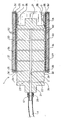
- the only figure in the drawing shows an intaglio cylinder. of the present invention in longitudinal section with the sleeve partially removed from the core.
- the illustrated embodiment of the intaglio cylinder essentially consists of a core 2 and a sleeve 3 surrounding it.
- the core 2 has the shape of a cylinder with end axles 21 for mounting the printing cylinder during the printing process.
- Inside the core 2, which otherwise consists of solid metal, generally steel, has a central air duct 22 and a number of air ducts 23 leading radially from the latter to the outer surface 25 of the core 2.
- the central air duct 22 is carried out on one side and is provided with a connecting piece 26 in the region of the end face of the one axle stub 21.
- a compressed air hose 4 can be connected to this connecting piece 26 by means of a suitable coupling 41.
- the sleeve 3 consists essentially of three layers, namely an inner layer 31, a middle layer 33 and an outer layer 34, which are each arranged concentrically to the axis of rotation of the printing cylinder 1.
- the inner layer 31 of the sleeve 3 consists of an elastic rubber material and has on its outside recesses 32 in the form of grooves running in the circumferential direction.
- the inside 36 of the inner layer 31, on the other hand, has a smooth surface.
- the middle layer 33 in the illustrated embodiment consists of a rigid material, here in the exemplary embodiment glass fiber reinforced plastic.
- a circumferential metal ring 35 which is connected to the two layers 31 and 33, for example by gluing, is arranged on the end face of the inner layer 31 and the middle layer 33.
- the rings 35 serve to transmit the electrical current required for the galvanic application of the outer layer 34.
- the outer layer 34 is - as is usual with gravure cylinders - a copper layer. This is also applied to the rings 35 on the end faces 34 'around the edges.
- the copper layer forming the outer layer 34 preferably has such a thickness since the edges in the region of the end faces 34 'can be rounded off in a sufficient manner.
- a nickel layer (not shown) can be applied between the middle layer 33 and the outer layer 34 to enable galvanic copper plating before the galvanization.
- the inner layer 31 and the middle layer 33 are preferably connected to one another by gluing, leaving the cutouts 32 free.
- the central air channel 22 is supplied with compressed air via the hose 4, which reaches the outside 25 of the core 2 via the radially extending channels 23.
- circumferential flat grooves 24 are arranged on the outside 25 of the core 2, through which the compressed air is distributed uniformly on the circumference of the core 2.
- the gap between the top 25 of the core 2 and the inside 36 of the sleeve 3 is shown exaggeratedly large; in practice, a gap of 0.1 mm or less is sufficient to be able to move the sleeve 3 relative to the core 2 with little effort.
- the inside 36 of the sleeve 3 engages intimately on the outside 25 of the core 2, whereby a sufficiently firm and dimensionally stable connection between the core 2 and the sleeve 3 is produced.
Priority Applications (1)
| Application Number | Priority Date | Filing Date | Title |
|---|---|---|---|
| AT86102237T ATE52965T1 (de) | 1985-03-29 | 1986-02-20 | Tiefdruckzylinder, bestehend aus einem kern und einer loesbar mit diesem verbundenen huelse. |
Applications Claiming Priority (3)
| Application Number | Priority Date | Filing Date | Title |
|---|---|---|---|
| DE3511530 | 1985-03-29 | ||
| DE19853511530 DE3511530A1 (de) | 1985-03-29 | 1985-03-29 | Tiefdruckzylinder |
| EP87101690A EP0278017A1 (fr) | 1987-02-07 | 1987-02-07 | Cylindre d'impression en creuse comportant un noyau et un manchon amovible |
Publications (3)
| Publication Number | Publication Date |
|---|---|
| EP0196443A2 true EP0196443A2 (fr) | 1986-10-08 |
| EP0196443A3 EP0196443A3 (en) | 1987-12-02 |
| EP0196443B1 EP0196443B1 (fr) | 1990-05-23 |
Family
ID=25830897
Family Applications (1)
| Application Number | Title | Priority Date | Filing Date |
|---|---|---|---|
| EP19860102237 Expired - Lifetime EP0196443B1 (fr) | 1985-03-29 | 1986-02-20 | Cylindre d'impression en creux comportant un noyau et un manchon amovible |
Country Status (1)
| Country | Link |
|---|---|
| EP (1) | EP0196443B1 (fr) |
Cited By (16)
| Publication number | Priority date | Publication date | Assignee | Title |
|---|---|---|---|---|
| EP0278017A1 (fr) * | 1987-02-07 | 1988-08-17 | Saueressig Gmbh & Co. | Cylindre d'impression en creuse comportant un noyau et un manchon amovible |
| EP0295319A1 (fr) * | 1987-06-19 | 1988-12-21 | Saueressig Gmbh & Co. | Cylindre gravé composé d'un noyau et d'une douille amovible |
| EP0546973A1 (fr) * | 1991-12-11 | 1993-06-16 | Jean Francille | Manchon porte-clichés pour cylindre d'impression flexographique |
| EP0683040A1 (fr) | 1994-05-19 | 1995-11-22 | Jean Francille | Procédé de fabrication d'un manchon pour machine d'impression et manchon obtenu |
| EP0704301A1 (fr) * | 1994-09-15 | 1996-04-03 | MAN Roland Druckmaschinen AG | Rouleau de pression pour la pression sans un canal |
| WO1997019793A1 (fr) * | 1995-11-30 | 1997-06-05 | Manuel Montenegro Criado | Enclume pour machines rotatives a rainurer et a decouper |
| US5840386A (en) * | 1996-02-22 | 1998-11-24 | Praxair S.T. Technology, Inc. | Sleeve for a liquid transfer roll and method for producing it |
| US5906149A (en) * | 1995-11-30 | 1999-05-25 | Montenegro Criado; Manuel | Anvil for rotary slotting and cutting machines |
| WO2000064675A1 (fr) * | 1999-04-23 | 2000-11-02 | Saueressig Gmbh & Co. | Couche extensible constituee d'un materiau compressible |
| FR2815572A1 (fr) * | 2000-10-24 | 2002-04-26 | Jean Francille | Manchon d'impression a montage par expansion radiale |
| US6905119B2 (en) * | 2002-06-19 | 2005-06-14 | Hewlett-Packard Development Company, L.P. | Pressurized roller |
| EP1745927A1 (fr) * | 2005-07-18 | 2007-01-24 | Hueck Folien GmbH & Co. KG | Cylindre d'impression comportant une chemise détachable |
| DE10039744B4 (de) * | 2000-08-16 | 2008-06-05 | Hueck Folien Gesellschaft M.B.H. | Spannzylinder zur Aufnahme und Befestigung einer zylindrischen Prägeform mit einer strukturierten Oberfläche |
| US8871431B2 (en) | 2011-08-08 | 2014-10-28 | Timothy Gotsick | Laminated flexographic printing sleeves and methods of making the same |
| RU2560321C2 (ru) * | 2010-09-24 | 2015-08-20 | Еуро-Композитс С.А. | Многослойная растяжимая гильза для цилиндра печатной машины, в частности для флексографической печати |
| CN107351519A (zh) * | 2017-08-22 | 2017-11-17 | 赣州彩盛印刷有限公司 | 一种凹版印刷机 |
Families Citing this family (3)
| Publication number | Priority date | Publication date | Assignee | Title |
|---|---|---|---|---|
| DE4341262C2 (de) * | 1993-01-22 | 1999-04-08 | Heidelberger Druckmasch Ag | Vorrichtung für die Reduzierung von Materialausbuchtungen auf einer rohrförmigen Druckhülse |
| DE10241800B4 (de) | 2002-09-06 | 2014-04-30 | Polywest Kunststofftechnik Saueressig & Partner Gmbh & Co. Kg | Hülse mit mehrschichtigem Aufbau für Druckmaschinen und Verfahren zu ihrer Herstellung |
| DE10345562B4 (de) * | 2003-10-01 | 2014-09-04 | Sächsische Walzengravur GmbH | Einweghülse zum lösbaren Befestigen entweder auf einer Trägerwalze oder auf einer Adapterhülse der Trägerwalze zum Drucken, Lackieren und Beschichten |
Citations (4)
| Publication number | Priority date | Publication date | Assignee | Title |
|---|---|---|---|---|
| US3015268A (en) * | 1958-04-04 | 1962-01-02 | Russell U Garrett | Laminated printing plate and process for making same |
| DE2700118A1 (de) * | 1976-01-08 | 1977-07-14 | Strachan & Henshaw Ltd | Druckwalze |
| EP0009360A1 (fr) * | 1978-09-13 | 1980-04-02 | Drg (Uk) Limited | Fabrication de douilles pour l'impression |
| GB2126689A (en) * | 1982-09-02 | 1984-03-28 | Saiag Spa | A roller having a covering of elastomer material |
-
1986
- 1986-02-20 EP EP19860102237 patent/EP0196443B1/fr not_active Expired - Lifetime
Patent Citations (4)
| Publication number | Priority date | Publication date | Assignee | Title |
|---|---|---|---|---|
| US3015268A (en) * | 1958-04-04 | 1962-01-02 | Russell U Garrett | Laminated printing plate and process for making same |
| DE2700118A1 (de) * | 1976-01-08 | 1977-07-14 | Strachan & Henshaw Ltd | Druckwalze |
| EP0009360A1 (fr) * | 1978-09-13 | 1980-04-02 | Drg (Uk) Limited | Fabrication de douilles pour l'impression |
| GB2126689A (en) * | 1982-09-02 | 1984-03-28 | Saiag Spa | A roller having a covering of elastomer material |
Cited By (21)
| Publication number | Priority date | Publication date | Assignee | Title |
|---|---|---|---|---|
| EP0278017A1 (fr) * | 1987-02-07 | 1988-08-17 | Saueressig Gmbh & Co. | Cylindre d'impression en creuse comportant un noyau et un manchon amovible |
| EP0295319A1 (fr) * | 1987-06-19 | 1988-12-21 | Saueressig Gmbh & Co. | Cylindre gravé composé d'un noyau et d'une douille amovible |
| US4864926A (en) * | 1987-06-19 | 1989-09-12 | Saueressig & Co. | Intaglio printing cylinder having a core and a sleeve releasably fastened thereto |
| EP0546973A1 (fr) * | 1991-12-11 | 1993-06-16 | Jean Francille | Manchon porte-clichés pour cylindre d'impression flexographique |
| FR2684924A1 (fr) * | 1991-12-11 | 1993-06-18 | Francille Jean | Manchon porte-cliches pour cylindre d'impression flexographique. |
| EP0683040A1 (fr) | 1994-05-19 | 1995-11-22 | Jean Francille | Procédé de fabrication d'un manchon pour machine d'impression et manchon obtenu |
| US6038975A (en) * | 1994-09-15 | 2000-03-21 | Man Roland Druckmaschinen Ag | Printing roller for channel-free printing |
| EP0704301A1 (fr) * | 1994-09-15 | 1996-04-03 | MAN Roland Druckmaschinen AG | Rouleau de pression pour la pression sans un canal |
| US5906149A (en) * | 1995-11-30 | 1999-05-25 | Montenegro Criado; Manuel | Anvil for rotary slotting and cutting machines |
| WO1997019793A1 (fr) * | 1995-11-30 | 1997-06-05 | Manuel Montenegro Criado | Enclume pour machines rotatives a rainurer et a decouper |
| US5840386A (en) * | 1996-02-22 | 1998-11-24 | Praxair S.T. Technology, Inc. | Sleeve for a liquid transfer roll and method for producing it |
| US6823787B1 (en) | 1999-04-23 | 2004-11-30 | Saueressig Gmbh & Co. | Expandable layer made of compressible material |
| WO2000064675A1 (fr) * | 1999-04-23 | 2000-11-02 | Saueressig Gmbh & Co. | Couche extensible constituee d'un materiau compressible |
| DE10039744B4 (de) * | 2000-08-16 | 2008-06-05 | Hueck Folien Gesellschaft M.B.H. | Spannzylinder zur Aufnahme und Befestigung einer zylindrischen Prägeform mit einer strukturierten Oberfläche |
| WO2002034522A1 (fr) * | 2000-10-24 | 2002-05-02 | Jean Francille | Manchon d"impression a montage par expansion radiale |
| FR2815572A1 (fr) * | 2000-10-24 | 2002-04-26 | Jean Francille | Manchon d'impression a montage par expansion radiale |
| US6905119B2 (en) * | 2002-06-19 | 2005-06-14 | Hewlett-Packard Development Company, L.P. | Pressurized roller |
| EP1745927A1 (fr) * | 2005-07-18 | 2007-01-24 | Hueck Folien GmbH & Co. KG | Cylindre d'impression comportant une chemise détachable |
| RU2560321C2 (ru) * | 2010-09-24 | 2015-08-20 | Еуро-Композитс С.А. | Многослойная растяжимая гильза для цилиндра печатной машины, в частности для флексографической печати |
| US8871431B2 (en) | 2011-08-08 | 2014-10-28 | Timothy Gotsick | Laminated flexographic printing sleeves and methods of making the same |
| CN107351519A (zh) * | 2017-08-22 | 2017-11-17 | 赣州彩盛印刷有限公司 | 一种凹版印刷机 |
Also Published As
| Publication number | Publication date |
|---|---|
| EP0196443A3 (en) | 1987-12-02 |
| EP0196443B1 (fr) | 1990-05-23 |
Similar Documents
| Publication | Publication Date | Title |
|---|---|---|
| EP0196443B1 (fr) | Cylindre d'impression en creux comportant un noyau et un manchon amovible | |
| DE19524707C2 (de) | Verfahren zur Herstellung einer nahtlosen Druckhülse, insbesondere für einen Flexodruckzylinder | |
| EP0819550B1 (fr) | Manchon à base de caoutchouc pour machines rotatives offset | |
| DE3511530A1 (de) | Tiefdruckzylinder | |
| EP0295319B1 (fr) | Cylindre gravé composé d'un noyau et d'une douille amovible | |
| DE1292958B (de) | Walze, insbesondere Druckereiwalze fuer den Textil- und Papierdruck | |
| EP0812686B1 (fr) | Procédé et dispositif pour mettre en place d'une plaque plane sur un cylindre porte-plaque arrangé en porte à faux d'une presse à imprimer | |
| EP1157855B1 (fr) | Manchon à base de caoutchouc, notamment pour machines rotatives offset | |
| EP0787597A2 (fr) | Manchon pour cylindre d'impression en creux, procédé pour la fabrication de ce cylindre et procédé de fonctionnement de l'appareil pour la fabrication | |
| EP1362697B1 (fr) | Dispositif pour manipuler des manchons d'impression | |
| EP0475084A1 (fr) | Support radial en forme de manchon | |
| EP1104347B1 (fr) | Dispositif de retenue pour manchons d'impression flexographique | |
| DE3633155A1 (de) | Druckzylinder, insbesondere fuer das flexodruckverfahren | |
| DE102007062791A1 (de) | Hülse für eine Druckwalze, Druckmaschine und Verfahren zum Ersetzen einer inneren Umfangsschicht der Hülse für eine Druckwalze | |
| EP0278017A1 (fr) | Cylindre d'impression en creuse comportant un noyau et un manchon amovible | |
| EP0032668A1 (fr) | Matrice pour le déformage dans le procédé à froid ou à demi-chaud | |
| EP1132209B1 (fr) | Cylindre tramé pour une presse flexographique | |
| CH646377A5 (de) | Rotationsdruckzylinder. | |
| DE10023742C2 (de) | Formzylinder einer Druckmaschine mit auswechselbaren Druckhülsen | |
| EP1316423A1 (fr) | Rouleau tramé et méthode pour sa production et retraitement | |
| EP1004455A2 (fr) | Manchon en matériau formable thermiquement et procédé pour sa production | |
| EP1628828B1 (fr) | Unite de blocage de mandrin concue pour les mandrins de rouleau imprimeur d'une presse rotative | |
| EP1967360A2 (fr) | Manchon et outil de serrage destinés à l'utilisation dans un système constitué d'un outil de serrage et d'au moins un manchon | |
| EP0053277A1 (fr) | Cylindres pour groupes d'impression de presses rotatives | |
| DE19718549B4 (de) | Druckmaschine |
Legal Events
| Date | Code | Title | Description |
|---|---|---|---|
| PUAI | Public reference made under article 153(3) epc to a published international application that has entered the european phase |
Free format text: ORIGINAL CODE: 0009012 |
|
| AK | Designated contracting states |
Kind code of ref document: A2 Designated state(s): AT BE CH DE FR GB IT LI NL SE |
|
| PUAL | Search report despatched |
Free format text: ORIGINAL CODE: 0009013 |
|
| AK | Designated contracting states |
Kind code of ref document: A3 Designated state(s): AT BE CH DE FR GB IT LI NL SE |
|
| 17P | Request for examination filed |
Effective date: 19880304 |
|
| 17Q | First examination report despatched |
Effective date: 19890809 |
|
| GRAA | (expected) grant |
Free format text: ORIGINAL CODE: 0009210 |
|
| AK | Designated contracting states |
Kind code of ref document: B1 Designated state(s): AT BE CH DE FR GB IT LI NL SE |
|
| PG25 | Lapsed in a contracting state [announced via postgrant information from national office to epo] |
Ref country code: IT Free format text: LAPSE BECAUSE OF FAILURE TO SUBMIT A TRANSLATION OF THE DESCRIPTION OR TO PAY THE FEE WITHIN THE PRE;WARNING: LAPSES OF ITALIAN PATENTS WITH EFFECTIVE DATE BEFORE 2007 MAY HAVE OCCURRED AT ANY TIME BEFORE 2007. THE CORRECT EFFECTIVE DATE MAY BE DIFFERENT FROM THE ONE RECORDED.SCRIBED TIME-LIMIT Effective date: 19900523 Ref country code: FR Effective date: 19900523 Ref country code: BE Effective date: 19900523 |
|
| REF | Corresponds to: |
Ref document number: 52965 Country of ref document: AT Date of ref document: 19900615 Kind code of ref document: T |
|
| GBT | Gb: translation of ep patent filed (gb section 77(6)(a)/1977) | ||
| REF | Corresponds to: |
Ref document number: 3671409 Country of ref document: DE Date of ref document: 19900628 |
|
| RAP2 | Party data changed (patent owner data changed or rights of a patent transferred) |
Owner name: SAUERESSIG GMBH + CO. |
|
| REG | Reference to a national code |
Ref country code: CH Ref legal event code: PFA Free format text: SAUERESSIG GMBH + CO. |
|
| PG25 | Lapsed in a contracting state [announced via postgrant information from national office to epo] |
Ref country code: NL Effective date: 19900907 |
|
| EN | Fr: translation not filed | ||
| PG25 | Lapsed in a contracting state [announced via postgrant information from national office to epo] |
Ref country code: AT Effective date: 19910220 Ref country code: GB Effective date: 19910220 |
|
| PG25 | Lapsed in a contracting state [announced via postgrant information from national office to epo] |
Ref country code: SE Effective date: 19910221 |
|
| PG25 | Lapsed in a contracting state [announced via postgrant information from national office to epo] |
Ref country code: CH Effective date: 19910228 Ref country code: LI Effective date: 19910228 |
|
| PLBE | No opposition filed within time limit |
Free format text: ORIGINAL CODE: 0009261 |
|
| STAA | Information on the status of an ep patent application or granted ep patent |
Free format text: STATUS: NO OPPOSITION FILED WITHIN TIME LIMIT |
|
| 26N | No opposition filed | ||
| GBPC | Gb: european patent ceased through non-payment of renewal fee | ||
| REG | Reference to a national code |
Ref country code: CH Ref legal event code: PL |
|
| PG25 | Lapsed in a contracting state [announced via postgrant information from national office to epo] |
Ref country code: DE Effective date: 19911101 |
|
| EUG | Se: european patent has lapsed |
Ref document number: 86102237.4 Effective date: 19911008 |