EP0196443A2 - Intaglio printing cylinder comprising a core and a detachable sleeve - Google Patents
Intaglio printing cylinder comprising a core and a detachable sleeve Download PDFInfo
- Publication number
- EP0196443A2 EP0196443A2 EP86102237A EP86102237A EP0196443A2 EP 0196443 A2 EP0196443 A2 EP 0196443A2 EP 86102237 A EP86102237 A EP 86102237A EP 86102237 A EP86102237 A EP 86102237A EP 0196443 A2 EP0196443 A2 EP 0196443A2
- Authority
- EP
- European Patent Office
- Prior art keywords
- sleeve
- core
- layer
- gravure cylinder
- cylinder according
- Prior art date
- Legal status (The legal status is an assumption and is not a legal conclusion. Google has not performed a legal analysis and makes no representation as to the accuracy of the status listed.)
- Granted
Links
Images
Classifications
-
- B—PERFORMING OPERATIONS; TRANSPORTING
- B41—PRINTING; LINING MACHINES; TYPEWRITERS; STAMPS
- B41N—PRINTING PLATES OR FOILS; MATERIALS FOR SURFACES USED IN PRINTING MACHINES FOR PRINTING, INKING, DAMPING, OR THE LIKE; PREPARING SUCH SURFACES FOR USE AND CONSERVING THEM
- B41N1/00—Printing plates or foils; Materials therefor
- B41N1/16—Curved printing plates, especially cylinders
- B41N1/22—Curved printing plates, especially cylinders made of other substances
-
- B—PERFORMING OPERATIONS; TRANSPORTING
- B41—PRINTING; LINING MACHINES; TYPEWRITERS; STAMPS
- B41F—PRINTING MACHINES OR PRESSES
- B41F27/00—Devices for attaching printing elements or formes to supports
- B41F27/10—Devices for attaching printing elements or formes to supports for attaching non-deformable curved printing formes to forme cylinders
- B41F27/105—Devices for attaching printing elements or formes to supports for attaching non-deformable curved printing formes to forme cylinders for attaching cylindrical printing formes
Definitions
- the invention relates to a gravure cylinder, consisting of a core and a sleeve releasably connected thereto, the core being essentially solid and made of metal and provided with channels for guiding compressed air to its outer surface, and wherein the sleeve by means of a Compressed air generated air cushion can be pushed onto and removed from the core.
- Gravure cylinders of the type mentioned are known per se to the person skilled in the art in the field of printing press technology from tests in the relevant industry. Their purpose is to simplify the handling of the printing cylinders and to reduce the cost of transportation, since the cores remain in the printing shop and only the sleeves without a core are transported back and forth between the engraving shop and the printing shop.
- Such an intaglio cylinder offers the advantage that the inside diameter of the sleeve can be enlarged to a sufficient extent for being pulled onto the core and pulled off the core, and that at the same time the outside diameter and the outer shape of the sleeve are completely constant and constant.
- the sturdy sleeve ensures exact concentricity during the printing process and thus good print quality. Since the inner layer is only slightly elastic and slightly compressible, relative movements between the core and the sleeve can practically not occur with the pressure forces customary during printing. Due to the possible variation in the thickness of both the inner layer and the middle layer of the sleeve, sleeves with a wide variety of outer diameters or circumferences can be produced with the same inner diameter.
- a preferred material for the inner layer of the sleeve is rubber, because on the one hand it is freely adjustable in the required elasticity and on the other hand it can be machined with sufficient accuracy.
- the material of the inner layer of the sleeve is pore-free and that recesses are provided on the outside of the material which allow an enlargement of the inner diameter of the inner layer.
- the number, shape, depth and position of the cutouts allow the degree of compressibility of the inner layer and thus the degree of enlargeability of the inner diameter of the sleeve to be precisely determined.
- the arrangement of the recesses on the outside of the inner layer results in an advantageously smooth inner surface of the sleeve, which makes it easier to pull on and off and protects the inner layer from damage.
- a particularly favorable and advantageous shape of the cutouts on the outside of the inner layer of the sleeve is formed by at least one spiral-shaped, flat groove.
- This shape offers a particularly high shear stability of the inner layer, since the outside thereof is not divided into separate segments, but rather has a shape that is continuous in the circumferential direction.
- these recesses z. B. are relatively easy and precise to produce on a lathe.
- the inner layer of the sleeve including the recess is made on a nut core with the diameter of the core receiving the sleeve for the printing process.
- the thickness of the inner layer of the sleeve can be changed.
- the thickness of the inner layer of the sleeve is preferably between 3 and 30 mm. In this thickness range, both an adequate enlargement of the inside diameter and sufficient stability and accuracy of the printing cylinder are guaranteed.
- a preferred material for the middle layer of the sleeve which is responsible for producing the required stability, is glass fiber reinforced plastic. This material has a relatively low weight and offers very high mechanical stability and strength, even with low wall thicknesses, such as. B. is known from boat building. To further increase the stability, an additional reinforcement, preferably made of metal mesh or fabric, can be introduced into the material.
- a thin nickel layer is expediently applied to the outside of the middle layer.
- the application is preferably carried out by electroless nickel plating.
- the following copper layer can then e.g. B. are generated galvanically.
- Another material which can advantageously be used for the middle layer of the sleeve is metal, here preferably aluminum or steel. With this, an even higher stability and rigidity of the sleeve can be achieved, but this is associated with a higher weight of the sleeve. Which material is ultimately used in a specific case depends on the needs and requirements of the user and the size of the printing cylinder.
- a variation in the thickness of the middle layer of the sleeve can also be used to produce different outer diameters of the sleeve with a constant core diameter.
- the thickness of the middle layer of the sleeve is preferably between 3 and 50 mm. On the one hand, this range of thicknesses allows a very wide gradation of the core diameter and, on the other hand, ensures sufficient rigidity of the sleeve without its weight becoming too high for easy handling.
- a ring of electrically conductive material is arranged in the area of the inner and middle layer, the inner diameter of which is slightly larger than that of the inner layer and the outer diameter of which approximately corresponds to the outer diameter of the middle layer.
- These rings can be used to conduct current during the electroplating in a known manner.
- the end of the copper layer around the edges can also be applied to the outer surface of the rings, which improves the durability of the copper layer on the remaining part of the sleeve and thus the service life of the printing cylinder.
- the impression cylinder is painted.
- the present invention also provides that the core has circumferential flat grooves extending from the ends of the channels for guiding the compressed air on its outer surface. This ensures a uniform distribution of the compressed air and thus the forces generated by it on the inside of the sleeve. Forces of force on the sleeve, which lead to a deviation from the desired exact cylinder shape, are avoided.
- the number of channels or bores to be introduced into the core for guiding the compressed air to the outside of the core can be reduced in a cost-saving manner.
- FIG. 1 A preferred exemplary embodiment of the invention is explained in more detail below with reference to a drawing.
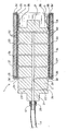
- the only figure in the drawing shows an intaglio cylinder. of the present invention in longitudinal section with the sleeve partially removed from the core.
- the illustrated embodiment of the intaglio cylinder essentially consists of a core 2 and a sleeve 3 surrounding it.
- the core 2 has the shape of a cylinder with end axles 21 for mounting the printing cylinder during the printing process.
- Inside the core 2, which otherwise consists of solid metal, generally steel, has a central air duct 22 and a number of air ducts 23 leading radially from the latter to the outer surface 25 of the core 2.
- the central air duct 22 is carried out on one side and is provided with a connecting piece 26 in the region of the end face of the one axle stub 21.
- a compressed air hose 4 can be connected to this connecting piece 26 by means of a suitable coupling 41.
- the sleeve 3 consists essentially of three layers, namely an inner layer 31, a middle layer 33 and an outer layer 34, which are each arranged concentrically to the axis of rotation of the printing cylinder 1.
- the inner layer 31 of the sleeve 3 consists of an elastic rubber material and has on its outside recesses 32 in the form of grooves running in the circumferential direction.
- the inside 36 of the inner layer 31, on the other hand, has a smooth surface.
- the middle layer 33 in the illustrated embodiment consists of a rigid material, here in the exemplary embodiment glass fiber reinforced plastic.
- a circumferential metal ring 35 which is connected to the two layers 31 and 33, for example by gluing, is arranged on the end face of the inner layer 31 and the middle layer 33.
- the rings 35 serve to transmit the electrical current required for the galvanic application of the outer layer 34.
- the outer layer 34 is - as is usual with gravure cylinders - a copper layer. This is also applied to the rings 35 on the end faces 34 'around the edges.
- the copper layer forming the outer layer 34 preferably has such a thickness since the edges in the region of the end faces 34 'can be rounded off in a sufficient manner.
- a nickel layer (not shown) can be applied between the middle layer 33 and the outer layer 34 to enable galvanic copper plating before the galvanization.
- the inner layer 31 and the middle layer 33 are preferably connected to one another by gluing, leaving the cutouts 32 free.
- the central air channel 22 is supplied with compressed air via the hose 4, which reaches the outside 25 of the core 2 via the radially extending channels 23.
- circumferential flat grooves 24 are arranged on the outside 25 of the core 2, through which the compressed air is distributed uniformly on the circumference of the core 2.
- the gap between the top 25 of the core 2 and the inside 36 of the sleeve 3 is shown exaggeratedly large; in practice, a gap of 0.1 mm or less is sufficient to be able to move the sleeve 3 relative to the core 2 with little effort.
- the inside 36 of the sleeve 3 engages intimately on the outside 25 of the core 2, whereby a sufficiently firm and dimensionally stable connection between the core 2 and the sleeve 3 is produced.
Abstract
Description
Die Erfindung betrifft einen Tiefdruckzylinder, bestehend aus einem Kern und einer lösbar mit diesem verbundenen Hülse, wobei der Kern im wesentlichen massiv ist und aus Metall besteht und mit Kanälen zur Führung von Druckluft zu seiner Außenfläche versehen ist, und wobei die Hülse mittels eines durch die Druckluft erzeugbaren Luftpolsters auf den Kern aufschiebbar und von diesem abziehbar ist.The invention relates to a gravure cylinder, consisting of a core and a sleeve releasably connected thereto, the core being essentially solid and made of metal and provided with channels for guiding compressed air to its outer surface, and wherein the sleeve by means of a Compressed air generated air cushion can be pushed onto and removed from the core.
Tiefdruckzylinder der genannten Art sind dem Fachmann auf den Gebiet der Druckmaschinentechnik aus Versuchen der einschlägigen Industrie an sich bekannt. Sie haben den Zweck, die Handhabung der Druckzylinder zu vereinfachen und den Transport zu verbilligen, indem die Kerne im Druckereibetrieb verbleiben und lediglich die Hülsen ohne Kern zwischen Gravurbetrieb und Druckerei hin und her transportiert werden.Gravure cylinders of the type mentioned are known per se to the person skilled in the art in the field of printing press technology from tests in the relevant industry. Their purpose is to simplify the handling of the printing cylinders and to reduce the cost of transportation, since the cores remain in the printing shop and only the sleeves without a core are transported back and forth between the engraving shop and the printing shop.
In der Praxis haben sich diese Druckzylinder aber noch nicht durchsetzen können. Der Grund hierfür ist die bisher mangelhafte Qualität der Druckzylinder und des Druckergebnisses derartiger Druckzylinder. Die Ursache für die mangelnde Druckqualität sind in der Ausgestaltung der Hülse zu suchen. Die bekannten Hülsen sind so ausgeführt, daß sie eine gewisse Elastizität aufweisen und unter der Einwirkung von Druckluft aufweitbar sind. Hierzu werden z. B. elastische Metalle, wie Nickel, als Hülsenmaterial unterhalb der notwendigerweise vorhandenen äuteren Kupferschicht verwendet. Zur Gewährleistung einer für die erforderliche Aufweitung noch ausreichenden Elastizität der Hülse muj diese relativ dünnwandig ausgeführt sein. Dies wiederum hat zur Folge, daf sich die äufere Kupferschicht im Einsatz leicht von ihrer Unterlage löst und daß so der Druckzylinder unbrauchbar wird. Außerdem besteht die Gefahr, daß die dünnwandigen Hülsen beim Transport oder bei der Handhabung beschädigt werden.In practice, however, these pressure cylinders have not yet been able to establish themselves. The reason for this is the poor quality of the printing cylinders and the printing result of such printing cylinders. The reason for the poor print quality can be found in the design of the sleeve. The known sleeves are designed so that they have a certain elasticity and expandable under the influence of compressed air. For this purpose, e.g. B. elastic metals, such as nickel, used as the sleeve material below the necessarily existing outer copper layer. To ensure that the sleeve has sufficient elasticity for the required expansion, it must be made relatively thin-walled. This in turn has the consequence that the outer copper layer easily detaches from its base in use and the printing cylinder is thus unusable. There is also a risk that the thin-walled sleeves will be damaged during transport or handling.
Dies deutet bereits auf den nächsten Nachteil hin, der darin besteht, dal trotz der Trennbarkeit von Kern und Hülse die Zahl der vorzuhaltenden, unterschiedlich groten Kerne nicht oder nicht wesentlich vermindert werden kann. Bei beiden bekannten Hülsenausführungen ist die Variationsbreite des Außendurchmessers der Hülse bei festem Innendurchmesser, d. h. festem Aufendurchmesser des Kerns, sehr begrenzt.This already indicates the next disadvantage, which is that, despite the separability of the core and the sleeve, the number of cores of different sizes to be kept cannot be reduced or can not be reduced significantly. In both known sleeve designs, the range of variation of the outer diameter of the sleeve with a fixed inner diameter, i. H. fixed outer diameter of the core, very limited.
Es stellt sich daher die Aufgabe, einen Tiefdruckzylinder der eingangs genannten Art zu schaffen, der die aufgeführten Nachteile vermeidet, und der insbesondere ein einwandfreies, einem einstückigen Druckzylinder gleichwertiges Druckergebnis gewährleistet, der eine deutliche Reduzierung der vorzuhaltenden Kerngrößen erlaubt und bei dem die Hülse eine für den Druckbetrieb und den Transport sicher ausreichende Stabilität aufweist.It is therefore the task of creating an intaglio cylinder of the type mentioned at the outset, which avoids the disadvantages mentioned, and in particular a flawless, one-piece printing cylinder equivalent printing result guaranteed, which allows a significant reduction in the core sizes to be kept and in which the sleeve has sufficient stability for printing and transportation.
Die Lösung dieser Aufgabe gelingt erfindungsgemäß durch einen Tiefdruckzylinder der eingangs genannten Art, bei dem die Hülse aus zumindest drei konzentrischen Lagen besteht,
- daJ die innere Lage aus einem geringelastischen Material besteht und geringfügig kompressibel ist,
- dab. die mittlere Lage aus einem starren und in sich stabilen Material besteht,
- dab. die innere, und/oder die mittlere jeweils in ihrer Dicke variieren können, und
- daß die äufere Lage eine Kupferschicht ist.
- that the inner layer is made of a low elastic material and is slightly compressible,
- dab. the middle layer consists of a rigid and inherently stable material,
- dab. the inner and / or the middle can vary in their thickness, and
- that the outer layer is a copper layer.
Ein derartiger Tiefdruckzylinder bietet den Vorteil, daß der Innendurchmesser der Hülse in einem für das Aufziehen auf den Kern und das Abziehen von dem Kern ausreichenden Maß vergröBerbar ist und daß zugleich der Auaen- durchmesser und die äußere Form der Hülse völlig konstant und beständig sind. Die stabile Hülse gewährleistet einen exakten Rundlauf während des Druckvorganges und damit eine gute Druckqualität. Da die innere Lage lediglich geringelastisch und geringfügig kompressibel ist, können Relativbewegungen zwischen Kern und Hülse bei den während des Druckens üblichen Andruckkräften praktisch nicht auftreten. Durch die mögliche Variation der Dicke sowohl der inneren Lage als auch der mittleren Lage der Hülse können bei gleichem Innendurchmesser Hülsen mit den unterschiedlichsten Außendurchmessern bzw. Umfängen hergestellt werden. Die Zahl der erforderlichen Kerndurchmesser kann damit durch eine relativ weite Abstufung drastisch verringert werden. Aufgrund ihrer Eigenstabilität ist die Hülse des erfindungsgemäBen Tiefdruckzylinders gegen Verformungen und Beschädigungen bei Handhabung und Transport weitestgehend geschützt, ohne dab aufwendige Vorsichtsmaßnahmen erforderlich wären.Such an intaglio cylinder offers the advantage that the inside diameter of the sleeve can be enlarged to a sufficient extent for being pulled onto the core and pulled off the core, and that at the same time the outside diameter and the outer shape of the sleeve are completely constant and constant. The sturdy sleeve ensures exact concentricity during the printing process and thus good print quality. Since the inner layer is only slightly elastic and slightly compressible, relative movements between the core and the sleeve can practically not occur with the pressure forces customary during printing. Due to the possible variation in the thickness of both the inner layer and the middle layer of the sleeve, sleeves with a wide variety of outer diameters or circumferences can be produced with the same inner diameter. The number of core diameters required can thus be drastically reduced by a relatively wide gradation. Because of their inherent stability, the sleeve of the fiction is gravure cylinders are largely protected against deformation and damage during handling and transport, without the need for expensive precautionary measures.
Ein bevorzugtes Material für die innere Lage der Hülse ist Cummi, weil es zum einen in der erforderlichen Elastizität frei einstellbar ist und zum anderen in ausreichender Exaktheit bearbeitbar ist.A preferred material for the inner layer of the sleeve is rubber, because on the one hand it is freely adjustable in the required elasticity and on the other hand it can be machined with sufficient accuracy.
Zwar könnte zur Gewährleistung der Kompressibilität ein poröses Material als inneres Material der Hülse verwendet werden, doch ergibt sich hier der Nachteil, daß das Gesamtvolumen der Porenräume und damit das MaB der Kompressibilität nicht exakt bestimmbar und gleichmäßig innerhalb des Materials verteilbar ist. Es ist deshalb bevorzugt vorgesehen, daB das Material der inneren Lage der Hülse porenfrei ist und daß auf der Außenseite des Materials eine Vergrößerung des Innendurchmessers der inneren Lage erlaubende Aussparungen angeordnet sind. Es kann so durch die Zahl, Form, Tiefe und Lage der Aussparungen das MaB der Kompressibilität der inneren Lage und damit das MaB der Vergrößerbarkeit des Innendurchmessers der Hülse exakt festgelegt werden. Die Anordnung der Aussparungen auf der Auenseite der inneren Lage ergibt eine vorteilhaft glatte Innenfläche der Hülse, was das Auf- und Abziehen erleichtert und die innere Lage vor Beschädigungen schützt.Although a porous material could be used as the inner material of the sleeve to ensure the compressibility, there is the disadvantage here that the total volume of the pore spaces and thus the degree of compressibility cannot be determined exactly and can be distributed evenly within the material. It is therefore preferably provided that the material of the inner layer of the sleeve is pore-free and that recesses are provided on the outside of the material which allow an enlargement of the inner diameter of the inner layer. The number, shape, depth and position of the cutouts allow the degree of compressibility of the inner layer and thus the degree of enlargeability of the inner diameter of the sleeve to be precisely determined. The arrangement of the recesses on the outside of the inner layer results in an advantageously smooth inner surface of the sleeve, which makes it easier to pull on and off and protects the inner layer from damage.
Für das die innere Lage bildende Gummi ist eine Shore-Härte zwischen 70 und 110, vorzugsweise zwischen 85 und 90 vorgesehen. Hiermit läßt sich nach praktischen Versuchen bei Aussparungen im Material von etwa 5 % des Gesamtvolumens der inneren Lage, bei etwa 5 mm Materialstärke und einem Luftdruck von etwa 6 bar eine Vergröte- rung des Innendurchmessers von etwa 0,1 mm erreichen, was für ein leichtgängiges Aufziehen und Abziehen der Hülse ausreicht. Bei nichtangelegter Druckluft konnte dagegen die Hülse mit einer Abzugkraft von 1500 kp nicht vom Kern abgezogen werden, wie sich bei Versuchen zeigte.A Shore hardness between 70 and 110, preferably between 85 and 90, is provided for the rubber forming the inner layer. After practical trials with recesses in the material of approximately 5% of the total volume of the inner layer, with a material thickness of approximately 5 mm and an air pressure of approximately 6 bar, this allows the internal diameter to increase by approximately 0.1 mm, which is easy Winding up and pulling off the Sleeve is sufficient. When compressed air was not applied, however, the sleeve could not be pulled off the core with a pulling force of 1500 kp, as was shown in tests.
Eine besonders günstige und vorteilhafte Form der Aussparungen auf der Außenseite der inneren Lage der Hülse wird durch wenigstens eine wendelartig umlaufende flache Nut gebildet. Diese Form bietet eine besonders hohe Scherstabilität der inneren Lage, da deren Außenseite nicht in separate Segmente geteilt ist, sondern eine in Umfangsrichtung durchgängige Form aufweist. Hinzu kommt, dab diese Aussparungen z. B. auf einer Drehbank relativ leicht und exakt herstellbar sind.A particularly favorable and advantageous shape of the cutouts on the outside of the inner layer of the sleeve is formed by at least one spiral-shaped, flat groove. This shape offers a particularly high shear stability of the inner layer, since the outside thereof is not divided into separate segments, but rather has a shape that is continuous in the circumferential direction. In addition, these recesses z. B. are relatively easy and precise to produce on a lathe.
Zur Gewährleistung einer exakten Einhaltung des Innendurchmessers, der Rundheit und Konzentrizität der Hülse ist vorgesehen, daß zumindest die innere Lage der Hülse einschließlich der Aussparung auf einem Mutterkern mit dem Durchmesser des die Hülse für den Druckvorgang aufnehmenden Kerns hergestellt ist.In order to ensure exact compliance with the inside diameter, the roundness and concentricity of the sleeve, it is provided that at least the inner layer of the sleeve including the recess is made on a nut core with the diameter of the core receiving the sleeve for the printing process.
Für die Variation der Außendurchmesser der Hülse bei konstantem Kerndurchmesser ist u. a. die Dicke der inneren Lage der Hülse veränderbar. Vorzugsweise beträgt die Dicke der inneren Lage der Hülse zwischen 3 und 30 mm. In diesem Dickenbereich wird sowohl eine ausreichende Vergröserbarkeit des Innendurchmessers als auch eine genügende Stabilität und Exaktheit des Druckzylinders gewährleistet.For the variation of the outer diameter of the sleeve with a constant core diameter is u. a. the thickness of the inner layer of the sleeve can be changed. The thickness of the inner layer of the sleeve is preferably between 3 and 30 mm. In this thickness range, both an adequate enlargement of the inside diameter and sufficient stability and accuracy of the printing cylinder are guaranteed.
Ein bevorzugtes haterial für die mittlere Lage der Hülse, die für die Erzeugung der erforderlichen Stabilität verantwortlich ist, ist glasfaserverstärkter Kunststoff. Dieses Material besitzt ein relativ geringes Gewicht und bietet schon bei geringen Wandungsstärken eine sehr hohe mechanische Stabilität und Beanspruchbarkeit, wie z. B. aus dem Bootsbau bekannt ist. Zur weiteren Erhöhung der Stabilität kann in das Material noch eine zusätzliche Armierung, vorzugsweise aus Metallgitter- oder Gewebe eingebracht sein.A preferred material for the middle layer of the sleeve, which is responsible for producing the required stability, is glass fiber reinforced plastic. This material has a relatively low weight and offers very high mechanical stability and strength, even with low wall thicknesses, such as. B. is known from boat building. To further increase the stability, an additional reinforcement, preferably made of metal mesh or fabric, can be introduced into the material.
Zur Sicherstellung einer intensiven und dauerhaften Verbindung der äuseren Kupferschicht mit dem übrigen Teil der Hülse ist zweckmäßig auf die Außenseite der mittleren Lage eine Nickelschicht geringer Dicke aufgebracht. Die Aufbringung erfolgt vorzugsweise durch stromlose Vernickelung. Die folgende Kupferschicht kann dann z. B. galvanisch erzeugt werden.To ensure an intensive and permanent connection of the outer copper layer to the rest of the sleeve, a thin nickel layer is expediently applied to the outside of the middle layer. The application is preferably carried out by electroless nickel plating. The following copper layer can then e.g. B. are generated galvanically.
Ein anderes für die mittlere Lage der Hülse vorteilhaft verwendbares Material ist metall, hier vorzugsweise Aluminium oder Stahl. Hiermit kann eine noch höhere Stabilität und Starrheit der Hülse erreicht werden, was aber mit einem höheren Gewicht der Hülse verbunden ist. Welches Material letztendlich im konkreten Fall verwendet wird, hängt von den Erfordernissen und Ansprüchen des Anwenders sowie von der Größe des Druckzylinders ab.Another material which can advantageously be used for the middle layer of the sleeve is metal, here preferably aluminum or steel. With this, an even higher stability and rigidity of the sleeve can be achieved, but this is associated with a higher weight of the sleeve. Which material is ultimately used in a specific case depends on the needs and requirements of the user and the size of the printing cylinder.
Neben der Variation der Dicke der inneren Lage der Hülse kann auch eine Variation der Dicke der mittleren Lage der Hülse zur Erzeugung unterschiedlicher Außendurchmesser der Hülse bei konstantem Kerndurchmesser dienen. Die Dicke der mittleren Lage der Hülse beträgt dabei vorzugsweise zwischen 3 und 50 mm. Dieser Dickenbereich erlaubt einerseits eine sehr weite Abstufung der Kerndurchmesser und gewährleistet andererseits eine ausreichende Starrheit der Hülse, ohne daß deren Gewicht für eine einfache Handhabung zu hoch wird.In addition to the variation in the thickness of the inner layer of the sleeve, a variation in the thickness of the middle layer of the sleeve can also be used to produce different outer diameters of the sleeve with a constant core diameter. The thickness of the middle layer of the sleeve is preferably between 3 and 50 mm. On the one hand, this range of thicknesses allows a very wide gradation of the core diameter and, on the other hand, ensures sufficient rigidity of the sleeve without its weight becoming too high for easy handling.
Zum mechanischen Schutz der Stirnseiten der Hülse und zur Ermöglichung eines galvanischen Verkupferns entsprechend dem Verfahren bei üblichen einstückigen Druckzylindern ist vorgesehen, daß an der Hülse stirnseitig im Bereich der inneren und mittleren Lage je ein Ring aus elektrisch leitendem Material angeordnet ist, dessen Innendurchmesser geringfügig größer ist als der der inneren Lage und dessen Außendurchmesser etwa dem Aui.endurchmesser der mittleren Lage entspricht. Über diese Ringe kann in bekannter Weise die Stromleitung während des Galvanisierens erfolgen. Ausserdem kann die Kupferschicht stirnseitig um die Kanten herum auch auf die Außenfläche det Ringe aufgebracht werden, was die Haltbarkeit der Kupferschicht auf dem übrigen Teil der Hülse und damit die Standzeit des Druckzylinders verbessert.For mechanical protection of the end faces of the sleeve and to enable galvanic copper-plating in accordance with the method in conventional one-piece pressure cylinders, it is provided that on the end face of the sleeve a ring of electrically conductive material is arranged in the area of the inner and middle layer, the inner diameter of which is slightly larger than that of the inner layer and the outer diameter of which approximately corresponds to the outer diameter of the middle layer. These rings can be used to conduct current during the electroplating in a known manner. In addition, the end of the copper layer around the edges can also be applied to the outer surface of the rings, which improves the durability of the copper layer on the remaining part of the sleeve and thus the service life of the printing cylinder.
Schlielich ist bei dem Druckzylinder gemäl. vorliegender Erfindung noch vorgesehen, dab der Kern auf seiner Auienfläche von den Enden der Kanäle für die Führung der Druckluft ausgehende, umlaufende flache Muten aufweist. Hierdurch wird eine gleichmäige Verteilung der Druckluft und damit der durch diese erzeugten Kräfte auf die Innenseite der Hülse gewährleistet. Krafteinwirkungen auf die Hülse, die zu einer Abweichung von der erwünschten exakten Zylinderform führen, werden so vermieden. Auterdem kann so die Zahl der in den Kern einzubringenden Kanäle oder Bohrungen zur Führung der Druckluft zur Kernauenseite kostensparend vermindert werden.Finally, the impression cylinder is painted. The present invention also provides that the core has circumferential flat grooves extending from the ends of the channels for guiding the compressed air on its outer surface. This ensures a uniform distribution of the compressed air and thus the forces generated by it on the inside of the sleeve. Forces of force on the sleeve, which lead to a deviation from the desired exact cylinder shape, are avoided. In addition, the number of channels or bores to be introduced into the core for guiding the compressed air to the outside of the core can be reduced in a cost-saving manner.
Im folgenden wird ein bevorzugtes Ausführungsbeispiel der Erfindung anhand einer Zeichnung näher erläutert. Die einzige Figur der Zeichnung zeigt einen Tiefdruckzylinder gemäf. der vorliegenden Erfindung im Längsschnitt mit teilweise vom Kern abgezogener Hülse.A preferred exemplary embodiment of the invention is explained in more detail below with reference to a drawing. The only figure in the drawing shows an intaglio cylinder. of the present invention in longitudinal section with the sleeve partially removed from the core.
Wie aus der Figur ersichtlich ist, besteht das dargestellte Ausführungsbeispiel des Tiefdruckzylinders im wesentlichen aus einem Kern 2 und einer diesen umgebenden Hülse 3. Der Kern 2 hat die Form eines Zylinders mit stirnseitigen Achnstummeln 21 zur Lagerung des Druckzylinders während des Druckvorganges. In seinem Inneren weist der ansonsten aus massivem Metall, im allgemeinen Stahl, bestehende Kern 2 einen zentralen Luftkanal 22 sowie eine Anzahl von von diesem radial nach aufen zur Außenfläche 25 des Kerns 2 führenden Luftkanälen 23 auf. Einseitig ist der zentrale Luftkanal 22 nach aulen durchgeführt und im bereich der Stirnseite des einen Achsstummels 21 mit einem Anschluistück 26 versehen. An dieses Anschlustück 26 ist mittels einer passenden Kupplung 41 ein Druckluftschlauch 4 anschliebar.As can be seen from the figure, the illustrated embodiment of the intaglio cylinder essentially consists of a
Die Hülse 3 besteht im wesentlichen aus drei Lagen, nämlich einer inneren Lage 31, einer mittleren Lage 33 und einer äußeren Lage 34, die jeweils konzentrisch zur Rotationsachse des Druckzylinders 1 angeordnet sind. Die innere Lage 31 der Hülse 3 besteht aus einem elastischen GuMmimaterial, und weist auf ihrer Außenseite Aussparungen 32 in Form von in Umfangsrichtung verlaufenden Nuten auf. Die Innenseite 36 der inneren Lage 31 ist dagegen glattflächig ausgeführt. Die mittlere Lage 33 besteht im dargestellten Ausführungsbeispiel aus einem starren Material, hier im Ausführungsbeispiel glasfaserverstärkter Kunststoff. An die innere Lage 31 und die mittlere Lage 33 ist stirnseitig auf jeder Seite ein umlaufender Metallring 35 angeordnet, der mit den beiden Lagen 31 und 33 beispielsweise durch Verklebung verbunden ist. Auer als mechanischer Schutz für die beiden Lagen 31 und 33 dienen die Ringe 35 der Übertragung des für eine galvanische Aufbringung der äueren Lage 34 erforderlichen elektrischen Stromes. Bei der äueren Lage 34 handelt es sich - wie bei Tiefdruckzylindern üblich - um eine Kupferschicht. Diese ist an den Stirnseiten 34' kantenumgreifend auch auf die Ringe 35 aufgebracht. Dabei weist die die äuere Lage 34 bildende Kupferschicht vorzugsweise eine solche Dicke auf, da die Kanten im Bereich der Stirnseiten 34' in ausreichender Weise abgerundet werden können.The
Zwischen der mittleren Lage 33 und der äueren Lage 34 kann zur Ermöglichung einer galvanischen Verkupferung vor der Galvanisierung eine nickelschicht (nicht dargestellt) aufgebracht werden.A nickel layer (not shown) can be applied between the
Die innere Lage 31 und die mittlere Lage 33 sind vorzugsweise unter Freilassung der Aussparungen 32 miteinander durch Verklebung verbunden.The
Zur Ermöglichung eines Abziehens der Hülse 3 vom Kern 2 bzw. eines Aufschiebens der Hülse 3 auf den Kern 2 wird der zentrale Luftkanal 22 über den Schlauch 4 mit Druckluft beschickt, die über die radial verlaufenden Kanäle 23 zur Außenseite 25 des Kerns 2 gelangt. Im Bereich der äueren Enden der radial verlaufenden Kanäle 23 sind auf der Außenseite 25 des Kerns 2 in Umfangsrichtung umlaufende flache Nuten 24 angeordnet, durch welche sich die Druckluft gleichmäig auf dem Umfang des Kerns 2 verteilt. Hierdurch wird zwischen der Aurenseite 25 des Kerns 2 und der Innenseite 36 der Hülse 3 ein Luftpolster von einer für ein leichtes Aufschieben bzw. Abziehen der Hülse 3 ausreichenden Dicke erzeugt. In der Figur ist der Spaltraum zwischen der Aufenseite 25 des Kerns 2 und der Innenseite 36 der Hülse 3 übertrieben grof dargestellt; in der Praxis genügt bereits ein Spaltraum von 0,1 mm oder weniger, um die Hülse 3 gegenüber dem Kern 2 mit geringem Kraftaufwand bewegen zu können. Nach Wegnahme des Druckes der zugeführten Luft, z. B. durch Abnehmen des Schlauches 4 vom Schlauchan- schlu 26 des Kerns 2 legt sich die Innenseite 36 der Hülse 3 innig an die Außenseite 25 des Kerns 2 an, wodurch eine ausreichend feste und formstabile Verbindung zwischen Kern 2 und Hülse 3 hergestellt wird.To enable the
Claims (14)
Priority Applications (1)
| Application Number | Priority Date | Filing Date | Title |
|---|---|---|---|
| AT86102237T ATE52965T1 (en) | 1985-03-29 | 1986-02-20 | GRAVITY PRESSURE CYLINDER, CONSISTING OF A CORE AND A SLEEVE DETACHABLE WITH THIS CONNECTED. |
Applications Claiming Priority (3)
| Application Number | Priority Date | Filing Date | Title |
|---|---|---|---|
| DE3511530 | 1985-03-29 | ||
| DE19853511530 DE3511530A1 (en) | 1985-03-29 | 1985-03-29 | LOW PRESSURE CYLINDER |
| EP87101690A EP0278017A1 (en) | 1987-02-07 | 1987-02-07 | Intaglio printing cylinder comprising a core and a detachable sleeve |
Publications (3)
| Publication Number | Publication Date |
|---|---|
| EP0196443A2 true EP0196443A2 (en) | 1986-10-08 |
| EP0196443A3 EP0196443A3 (en) | 1987-12-02 |
| EP0196443B1 EP0196443B1 (en) | 1990-05-23 |
Family
ID=25830897
Family Applications (1)
| Application Number | Title | Priority Date | Filing Date |
|---|---|---|---|
| EP19860102237 Expired - Lifetime EP0196443B1 (en) | 1985-03-29 | 1986-02-20 | Intaglio printing cylinder comprising a core and a detachable sleeve |
Country Status (1)
| Country | Link |
|---|---|
| EP (1) | EP0196443B1 (en) |
Cited By (16)
| Publication number | Priority date | Publication date | Assignee | Title |
|---|---|---|---|---|
| EP0278017A1 (en) * | 1987-02-07 | 1988-08-17 | Saueressig Gmbh & Co. | Intaglio printing cylinder comprising a core and a detachable sleeve |
| EP0295319A1 (en) * | 1987-06-19 | 1988-12-21 | Saueressig Gmbh & Co. | Engraved cylinder composed of a core and a detachable sleeve |
| EP0546973A1 (en) * | 1991-12-11 | 1993-06-16 | Jean Francille | Plate sleeve for flexographic printing cylinder |
| EP0683040A1 (en) | 1994-05-19 | 1995-11-22 | Jean Francille | Process for the manufacture of a sleeve for a printing machine, and sleeve obtained thereby |
| EP0704301A1 (en) * | 1994-09-15 | 1996-04-03 | MAN Roland Druckmaschinen AG | Pressure roll for channel-free pressure |
| WO1997019793A1 (en) * | 1995-11-30 | 1997-06-05 | Manuel Montenegro Criado | Anvil for rotary slotting and cutting machines |
| US5840386A (en) * | 1996-02-22 | 1998-11-24 | Praxair S.T. Technology, Inc. | Sleeve for a liquid transfer roll and method for producing it |
| US5906149A (en) * | 1995-11-30 | 1999-05-25 | Montenegro Criado; Manuel | Anvil for rotary slotting and cutting machines |
| WO2000064675A1 (en) * | 1999-04-23 | 2000-11-02 | Saueressig Gmbh & Co. | Expandable layer made of a compressible material |
| FR2815572A1 (en) * | 2000-10-24 | 2002-04-26 | Jean Francille | Composite sleeve for fitting to printing cylinder by radial expansion has inner deformable layer, compressible, non-stretch and packing layers |
| US6905119B2 (en) * | 2002-06-19 | 2005-06-14 | Hewlett-Packard Development Company, L.P. | Pressurized roller |
| EP1745927A1 (en) * | 2005-07-18 | 2007-01-24 | Hueck Folien GmbH & Co. KG | Printing roll with detachable printing sleeve |
| DE10039744B4 (en) * | 2000-08-16 | 2008-06-05 | Hueck Folien Gesellschaft M.B.H. | Clamping cylinder for holding and fixing a cylindrical embossing mold with a structured surface |
| US8871431B2 (en) | 2011-08-08 | 2014-10-28 | Timothy Gotsick | Laminated flexographic printing sleeves and methods of making the same |
| RU2560321C2 (en) * | 2010-09-24 | 2015-08-20 | Еуро-Композитс С.А. | Multilayer extensible sleeve for cylinder of printing machine, particularly for flexographic printing |
| CN107351519A (en) * | 2017-08-22 | 2017-11-17 | 赣州彩盛印刷有限公司 | A kind of intaglio press |
Families Citing this family (3)
| Publication number | Priority date | Publication date | Assignee | Title |
|---|---|---|---|---|
| DE4341262C2 (en) * | 1993-01-22 | 1999-04-08 | Heidelberger Druckmasch Ag | Device for reducing bulges of material on a tubular pressure sleeve |
| DE10241800B4 (en) * | 2002-09-06 | 2014-04-30 | Polywest Kunststofftechnik Saueressig & Partner Gmbh & Co. Kg | Multilayer sleeve for printing machines and method for its production |
| DE10345562B4 (en) * | 2003-10-01 | 2014-09-04 | Sächsische Walzengravur GmbH | Disposable sleeve for releasable attachment either on a support roller or on an adapter sleeve of the support roller for printing, painting and coating |
Citations (4)
| Publication number | Priority date | Publication date | Assignee | Title |
|---|---|---|---|---|
| US3015268A (en) * | 1958-04-04 | 1962-01-02 | Russell U Garrett | Laminated printing plate and process for making same |
| DE2700118A1 (en) * | 1976-01-08 | 1977-07-14 | Strachan & Henshaw Ltd | PRINT ROLLER |
| EP0009360A1 (en) * | 1978-09-13 | 1980-04-02 | Drg (Uk) Limited | Manufacture of printing sleeves |
| GB2126689A (en) * | 1982-09-02 | 1984-03-28 | Saiag Spa | A roller having a covering of elastomer material |
-
1986
- 1986-02-20 EP EP19860102237 patent/EP0196443B1/en not_active Expired - Lifetime
Patent Citations (4)
| Publication number | Priority date | Publication date | Assignee | Title |
|---|---|---|---|---|
| US3015268A (en) * | 1958-04-04 | 1962-01-02 | Russell U Garrett | Laminated printing plate and process for making same |
| DE2700118A1 (en) * | 1976-01-08 | 1977-07-14 | Strachan & Henshaw Ltd | PRINT ROLLER |
| EP0009360A1 (en) * | 1978-09-13 | 1980-04-02 | Drg (Uk) Limited | Manufacture of printing sleeves |
| GB2126689A (en) * | 1982-09-02 | 1984-03-28 | Saiag Spa | A roller having a covering of elastomer material |
Cited By (21)
| Publication number | Priority date | Publication date | Assignee | Title |
|---|---|---|---|---|
| EP0278017A1 (en) * | 1987-02-07 | 1988-08-17 | Saueressig Gmbh & Co. | Intaglio printing cylinder comprising a core and a detachable sleeve |
| EP0295319A1 (en) * | 1987-06-19 | 1988-12-21 | Saueressig Gmbh & Co. | Engraved cylinder composed of a core and a detachable sleeve |
| US4864926A (en) * | 1987-06-19 | 1989-09-12 | Saueressig & Co. | Intaglio printing cylinder having a core and a sleeve releasably fastened thereto |
| EP0546973A1 (en) * | 1991-12-11 | 1993-06-16 | Jean Francille | Plate sleeve for flexographic printing cylinder |
| FR2684924A1 (en) * | 1991-12-11 | 1993-06-18 | Francille Jean | SLEEVE HOLDER FOR FLEXOGRAPHIC PRINTING CYLINDER. |
| EP0683040A1 (en) | 1994-05-19 | 1995-11-22 | Jean Francille | Process for the manufacture of a sleeve for a printing machine, and sleeve obtained thereby |
| US6038975A (en) * | 1994-09-15 | 2000-03-21 | Man Roland Druckmaschinen Ag | Printing roller for channel-free printing |
| EP0704301A1 (en) * | 1994-09-15 | 1996-04-03 | MAN Roland Druckmaschinen AG | Pressure roll for channel-free pressure |
| US5906149A (en) * | 1995-11-30 | 1999-05-25 | Montenegro Criado; Manuel | Anvil for rotary slotting and cutting machines |
| WO1997019793A1 (en) * | 1995-11-30 | 1997-06-05 | Manuel Montenegro Criado | Anvil for rotary slotting and cutting machines |
| US5840386A (en) * | 1996-02-22 | 1998-11-24 | Praxair S.T. Technology, Inc. | Sleeve for a liquid transfer roll and method for producing it |
| US6823787B1 (en) | 1999-04-23 | 2004-11-30 | Saueressig Gmbh & Co. | Expandable layer made of compressible material |
| WO2000064675A1 (en) * | 1999-04-23 | 2000-11-02 | Saueressig Gmbh & Co. | Expandable layer made of a compressible material |
| DE10039744B4 (en) * | 2000-08-16 | 2008-06-05 | Hueck Folien Gesellschaft M.B.H. | Clamping cylinder for holding and fixing a cylindrical embossing mold with a structured surface |
| WO2002034522A1 (en) * | 2000-10-24 | 2002-05-02 | Jean Francille | Radial expansion mounted printing sleeve |
| FR2815572A1 (en) * | 2000-10-24 | 2002-04-26 | Jean Francille | Composite sleeve for fitting to printing cylinder by radial expansion has inner deformable layer, compressible, non-stretch and packing layers |
| US6905119B2 (en) * | 2002-06-19 | 2005-06-14 | Hewlett-Packard Development Company, L.P. | Pressurized roller |
| EP1745927A1 (en) * | 2005-07-18 | 2007-01-24 | Hueck Folien GmbH & Co. KG | Printing roll with detachable printing sleeve |
| RU2560321C2 (en) * | 2010-09-24 | 2015-08-20 | Еуро-Композитс С.А. | Multilayer extensible sleeve for cylinder of printing machine, particularly for flexographic printing |
| US8871431B2 (en) | 2011-08-08 | 2014-10-28 | Timothy Gotsick | Laminated flexographic printing sleeves and methods of making the same |
| CN107351519A (en) * | 2017-08-22 | 2017-11-17 | 赣州彩盛印刷有限公司 | A kind of intaglio press |
Also Published As
| Publication number | Publication date |
|---|---|
| EP0196443B1 (en) | 1990-05-23 |
| EP0196443A3 (en) | 1987-12-02 |
Similar Documents
| Publication | Publication Date | Title |
|---|---|---|
| EP0196443B1 (en) | Intaglio printing cylinder comprising a core and a detachable sleeve | |
| DE19524707C2 (en) | Process for producing a seamless printing sleeve, in particular for a flexographic printing cylinder | |
| EP0819550B1 (en) | Rubber sleeve for rotary offset printing presses | |
| DE3511530A1 (en) | LOW PRESSURE CYLINDER | |
| EP0295319B1 (en) | Engraved cylinder composed of a core and a detachable sleeve | |
| DE1292958B (en) | Roller, especially printing roller for textile and paper printing | |
| EP0812686B1 (en) | Method and device for mounting a flat printing plate to a cantilevered plate cylinder of a printing press | |
| EP1157855B1 (en) | Rubber sleeve, especially for rotary offset printing presses | |
| EP0787597A2 (en) | Sleeve for an intaglio printing cylinder, fabrication process therefore and working procedure of the manufacturing machine | |
| EP1362697B1 (en) | Device for handling printing sleeves | |
| EP0475084A1 (en) | Radial bushlike support | |
| EP1104347B1 (en) | Holding device for flexographic printing sleeves | |
| DE3633155A1 (en) | Impression cylinder, in particular for the flexographic printing method | |
| EP0278017A1 (en) | Intaglio printing cylinder comprising a core and a detachable sleeve | |
| DE102007062791A1 (en) | Cylindrical sleeve for printing roller of printing machine, is attached on outer periphery of corpus side of base printing roller provided on printing machine with inner peripheral layer | |
| EP0032668A1 (en) | Cold-process or semicold-process massive-forming die | |
| EP1132209B1 (en) | Screen roller for a flexographic press | |
| CH646377A5 (en) | ROTARY PRINTING CYLINDER. | |
| DE10023742C2 (en) | Forme cylinder of a printing press with exchangeable printing sleeves | |
| EP1316423A1 (en) | Engraved roller and method for its production and reprocessing | |
| EP1004455A2 (en) | Sleeve of thermally formable materials and method for its production | |
| EP1628828B1 (en) | Mandrel locking unit for printing roller mandrels in a rotary printing machine | |
| EP1967360A2 (en) | Sleeve and clamp tool for use in a system comprising one clamp tool and at least one sleeve | |
| EP0053277A1 (en) | Cylinders for printing units of rotary presses | |
| DE19718549B4 (en) | press |
Legal Events
| Date | Code | Title | Description |
|---|---|---|---|
| PUAI | Public reference made under article 153(3) epc to a published international application that has entered the european phase |
Free format text: ORIGINAL CODE: 0009012 |
|
| AK | Designated contracting states |
Kind code of ref document: A2 Designated state(s): AT BE CH DE FR GB IT LI NL SE |
|
| PUAL | Search report despatched |
Free format text: ORIGINAL CODE: 0009013 |
|
| AK | Designated contracting states |
Kind code of ref document: A3 Designated state(s): AT BE CH DE FR GB IT LI NL SE |
|
| 17P | Request for examination filed |
Effective date: 19880304 |
|
| 17Q | First examination report despatched |
Effective date: 19890809 |
|
| GRAA | (expected) grant |
Free format text: ORIGINAL CODE: 0009210 |
|
| AK | Designated contracting states |
Kind code of ref document: B1 Designated state(s): AT BE CH DE FR GB IT LI NL SE |
|
| PG25 | Lapsed in a contracting state [announced via postgrant information from national office to epo] |
Ref country code: IT Free format text: LAPSE BECAUSE OF FAILURE TO SUBMIT A TRANSLATION OF THE DESCRIPTION OR TO PAY THE FEE WITHIN THE PRE;WARNING: LAPSES OF ITALIAN PATENTS WITH EFFECTIVE DATE BEFORE 2007 MAY HAVE OCCURRED AT ANY TIME BEFORE 2007. THE CORRECT EFFECTIVE DATE MAY BE DIFFERENT FROM THE ONE RECORDED.SCRIBED TIME-LIMIT Effective date: 19900523 Ref country code: FR Effective date: 19900523 Ref country code: BE Effective date: 19900523 |
|
| REF | Corresponds to: |
Ref document number: 52965 Country of ref document: AT Date of ref document: 19900615 Kind code of ref document: T |
|
| GBT | Gb: translation of ep patent filed (gb section 77(6)(a)/1977) | ||
| REF | Corresponds to: |
Ref document number: 3671409 Country of ref document: DE Date of ref document: 19900628 |
|
| RAP2 | Party data changed (patent owner data changed or rights of a patent transferred) |
Owner name: SAUERESSIG GMBH + CO. |
|
| REG | Reference to a national code |
Ref country code: CH Ref legal event code: PFA Free format text: SAUERESSIG GMBH + CO. |
|
| PG25 | Lapsed in a contracting state [announced via postgrant information from national office to epo] |
Ref country code: NL Effective date: 19900907 |
|
| EN | Fr: translation not filed | ||
| PG25 | Lapsed in a contracting state [announced via postgrant information from national office to epo] |
Ref country code: AT Effective date: 19910220 Ref country code: GB Effective date: 19910220 |
|
| PG25 | Lapsed in a contracting state [announced via postgrant information from national office to epo] |
Ref country code: SE Effective date: 19910221 |
|
| PG25 | Lapsed in a contracting state [announced via postgrant information from national office to epo] |
Ref country code: CH Effective date: 19910228 Ref country code: LI Effective date: 19910228 |
|
| PLBE | No opposition filed within time limit |
Free format text: ORIGINAL CODE: 0009261 |
|
| STAA | Information on the status of an ep patent application or granted ep patent |
Free format text: STATUS: NO OPPOSITION FILED WITHIN TIME LIMIT |
|
| 26N | No opposition filed | ||
| GBPC | Gb: european patent ceased through non-payment of renewal fee | ||
| REG | Reference to a national code |
Ref country code: CH Ref legal event code: PL |
|
| PG25 | Lapsed in a contracting state [announced via postgrant information from national office to epo] |
Ref country code: DE Effective date: 19911101 |
|
| EUG | Se: european patent has lapsed |
Ref document number: 86102237.4 Effective date: 19911008 |