EP0196249B1 - Lighting system, especially for a water-tight airport coffer - Google Patents
Lighting system, especially for a water-tight airport coffer Download PDFInfo
- Publication number
- EP0196249B1 EP0196249B1 EP19860400463 EP86400463A EP0196249B1 EP 0196249 B1 EP0196249 B1 EP 0196249B1 EP 19860400463 EP19860400463 EP 19860400463 EP 86400463 A EP86400463 A EP 86400463A EP 0196249 B1 EP0196249 B1 EP 0196249B1
- Authority
- EP
- European Patent Office
- Prior art keywords
- lamp
- current
- current transformer
- transformer
- clipping
- Prior art date
- Legal status (The legal status is an assumption and is not a legal conclusion. Google has not performed a legal analysis and makes no representation as to the accuracy of the status listed.)
- Expired - Lifetime
Links
Images


Classifications
-
- H—ELECTRICITY
- H05—ELECTRIC TECHNIQUES NOT OTHERWISE PROVIDED FOR
- H05B—ELECTRIC HEATING; ELECTRIC LIGHT SOURCES NOT OTHERWISE PROVIDED FOR; CIRCUIT ARRANGEMENTS FOR ELECTRIC LIGHT SOURCES, IN GENERAL
- H05B41/00—Circuit arrangements or apparatus for igniting or operating discharge lamps
- H05B41/14—Circuit arrangements
- H05B41/46—Circuits providing for substitution in case of failure of the lamp
Definitions
- the invention lies in the fields of public lighting or intended for the public.
- FR-A 2,430,707 is already known for lighting installations comprising an AC power supply circuit, of the regulated current loop type.
- a regulated current loop which generally operates at alternating medium voltage, travels in series through the primary windings of medium voltage / low voltage transformers. Through their secondary, these transformers in turn each supply a plurality of lighting devices, electrically connected in series, and belonging to respective indicator boxes.
- Such indicator boxes are often used, especially in airports. Their front face is provided with an indication intended for the users, for example an arrow or a letter.
- these indicator boxes have mostly been fitted with metal halide filament lamps, similar to those used for beacon lights. A detailed example of the structure of such a known box will be given below.
- the main object of the present invention is to improve this kind of installation.
- the invention provides a lighting device suitable for being part of a lighting installation of the type defined above.
- each lighting device comprises a current transformer, the secondary of which supplies at least one fluorescent lamp, with its ignition / regulation members; the primaries of the current transformers of the various lighting devices are intended to be mounted in series in the secondary circuit of the medium-voltage / low-voltage transformer, the primary circuit of which is reminded that it is supplied by the regulated current loop; finally, the secondary of each current transformer is provided in parallel with clipping devices capable of consuming, when the associated lamp fails, a substantial fraction of the nominal energy required by the latter. This preserves the flow of nominal current to the primary windings of the other current transformers, thus ensuring the proper functioning of the rest of the installation.
- the clipping members consist of two high voltage clipping diodes, mounted in head to tail series.
- a tuning member capable of providing an overvoltage characteristic by resonance.
- this characteristic of overvoltage by resonance is adjusted so that the secondary alternating voltage supplied decreases very quickly as soon as the secondary load increases, which accelerates, the ignition of the fluorescent lamp, and that the current passing through the organs of clipping is greatly reduced as soon as the secondary voltage reaches the clipping value.
- Such a tuning device may include a capacitor.
- each lighting device comprises two lamps connected alternately by an inverter to the secondary of the current transformer, and switching means, which react to the number of lights of a first lamp during a time greater than its ignition time by actuating the inverter to put the second lamp into service.
- such a device may include a base plate provided with oblong fixing openings, and which supports a block of overmolded synthetic material, having an intermediate level where the lamp or lamps are mounted, and a higher level from which the terminals of the primary of the current transformer emerge; the electronic circuits and this transformer are embedded in said block.
- the switching means will then preferably comprise a photodetector housed in a column removably mounted on this block, and capable of bringing the photodetector substantially into contact with the illuminating part of the first lamp.
- FIG. 1 shows a medium voltage circuit MT, arranged in a regulated current loop BDCR, and comprising n times a medium voltage / low voltage transformer. This therefore has a medium voltage PMT primary and a low voltage secondary SBT each time.
- the low-voltage circuit thereof supplies several indicator boxes CI1 to C14 in series.
- each indicator box comprises for example two metal halide filament lamps, such as the lamps LF11 and LF12 for the box 01. Most often, these two lamps are arranged one at the top and the another in the lower part of the box.
- each box uses two 45 watt lamps electrically connected in series. All the boxes are themselves connected in series to the low voltage terminals of an isolation transformer, the primary of which is supplied by a constant current loop between 5.5 and 6.6 Amps.
- the electrical power consumed is therefore at least 90 watts per box. It is actually a little higher, if we consider the reactive current losses as well as in transformers.
- FIG. 2 defines the block diagram of an installation according to the invention, compared with FIG. 1.
- the structure is the same up to the low voltage circuit. Now, this one, which always passes through the indicator boxes CI1 to CI4, meets in each box a device D1 to D4, respectively. Each of these devices is mounted substantially in the center of the box. As will be seen below, it has two lamps capable of operating alternately, that is to say that one can make up for the deficiencies of the other.
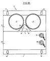
- FIGS. 3A and 3B show that, mechanically, a device D (one of the devices D1 to D4) comprises a base plate 1, on which is mounted a block of generally pyramidal shape, made of a synthetic material such as for example the two-component curing adhesive called araldite (registered trademark).
- araldite registered trademark
- the pyramid is doubly truncated. On one side, it is truncated at an intermediate level 21, where are provided orifices suitable for receiving the lamp bases L1 and L2, which are then mounted perpendicular to the flat face 1. At the top, the pyramid is truncated at one level upper 22, where terminals B1 and B2 appear which will be found later.
- this column 3 Between the two lamps L1 and L2, for example on the intermediate level 21, is mounted a column 3, pluggable electrically and mechanically by studs such as 31 and 32 on the block 2.
- this column 3 On the side of the lamp L1, this column 3 houses a photodetector 30, which is brought into contact with the illuminating part of this lamp. The mounting is preferably carried out so that this detector is very insensitive to other ambient light sources which may arise.
- the base plate 1 includes, for example at an angle, bean-shaped fixing holes such as 11, 12, 13 and 14.
- the lamps L1 and L2 are for example fluorescent lamps of the type with ballast and incorporated regulator, such as the lamps known in France under the name "Fairy". It turned out that a single 9 watt lamp could be enough to light a standardized airport box.
- FIG. 4 shows the electrical diagram of a device D according to the invention.
- the terminals B1 and B2 are terminals leading to the primary winding P of a current transformer TC, with its magnetic circuit CM.
- This primary winding S first receives in parallel a capacitor 50. This is followed in parallel by two high-voltage clipping diodes mounted head to tail, 51 and 52.
- this inverter I In its rest position, this inverter I closes the circuit on a lamp L1. In its working position, it closes it on the L2 lamp.
- the lamp L1 receives in parallel a resistance R10 of high value. And it is coupled to the photodetector 30 already mentioned.
- An auxiliary secondary winding SA provided in parallel with a surge suppressor 70, supplies a rectifier bridge 80, the outputs of which are provided in parallel with filtering produced by capacitor 91 and resistor 92.
- the output of this is used to supply an electronic control assembly, the input of which is defined by the photodetector 30.
- This one which is here phototransistor, has its collector connected to the positive terminal by a resistor 101, while its emitter joins the base of a transistor 102 whose emitter is grounded and whose collector joins the positive line by resistance 103.
- a first time constant is defined on the output of transistor 102 by resistor 104 and capacitor 10.7.
- the resistor 104 In parallel on the resistor 104 are mounted in series a diode 105 and a resistor 106, the cathode of the diode being on the side of the collector of the transistor 102.
- the resistor 104 is of significantly higher value than the resistor 106. This allows, when the phototransistor 30 finds that the lamp L1 does not light up, this information is inhibited for a time corresponding to a time at least equal to the nominal duration of ignition of the lamp. In practice, the ignition time of a lamp of this kind being approximately 2 seconds, the time constant applied to the detection is of the order of 10 seconds for example.
- the voltage available across the capacitor 107 rises, to be transmitted through a threshold device 108 consisting for example of a Zener diode at a Darlington power stage 110.
- a threshold device 108 consisting for example of a Zener diode at a Darlington power stage 110.
- This actuates via a resistor 111 a relay 120, which receives in parallel a capacitor 112.
- the relay 120 changes the state of the switch I, at the same time as '' it closes a contact 121, which ensures the self-maintenance of the relay.
- the tilting of the inverter has the effect of using the lamp L2, in place of the lamp L1.
- the terminals B1 and B2 of the current transformer are supplied by an effective current of 6.6 Amperes.
- Secondary S supplies the nominal current of the lamp used (9 watts or 18 watts in the examples concerned) at a voltage of approximately 220 volts.
- This corresponds to a current transformer having a high transformation ratio, of the order of about 70, note that if the value of the effective primary current is varied, this value being able to be modified by about 20%, this transformation ratio will vary.
- the power of the transformer is between 10 and 100 VA, preferably between 20 and 50 VA.
- lamps comprising a fluorescent tube and its supply members, integrated in the same glass, while retaining satisfactory operation.
- the invention thus makes it possible to improve the reliability of lighting the light boxes, while reducing their electrical consumption for equivalent lighting (we go from twice 45 VA to 20 VA).
- a secondary advantage is the reduction of the power of the emergency unit necessary to supply all the caissons of an airport, when the public electrical network does not work.
- the boxes Ci1 to CI4 equipped with the devices according to the invention are provided in a suitable number to correspond to the operating voltage of the low voltage secondary SBT of the medium voltage / low voltage transformer.
- the device according to the invention therefore functions like those of the prior art, which is another advantage.
Landscapes
- Circuit Arrangement For Electric Light Sources In General (AREA)
- Circuit Arrangements For Discharge Lamps (AREA)
Description
L'invention se situe dans les domaines de l'éclairage public ou destiné au public.The invention lies in the fields of public lighting or intended for the public.
On connaît déjà par FR-A 2 430 707 des installations d'éclairage comprenant un circuit d'alimentation de puissance en courant alternatif, du genre boucle de courant régulé. Une telle boucle de courant régulé, qui opère en général en moyenne tension alternative, parcourt en série les enroulements primaires de transformateurs moyenne tension/basse tension. Par leurs secondaires, ces transformateurs alimentent à leur tour chacun une pluralité de dispositifs d'éclairage, montés électriquement en série, et appartenant à des caissons indicateurs respectifs.FR-A 2,430,707 is already known for lighting installations comprising an AC power supply circuit, of the regulated current loop type. Such a regulated current loop, which generally operates at alternating medium voltage, travels in series through the primary windings of medium voltage / low voltage transformers. Through their secondary, these transformers in turn each supply a plurality of lighting devices, electrically connected in series, and belonging to respective indicator boxes.
De tels caissons indicateurs sont souvent utilisés, en particulier dans les aéroports. Leur face avant est munie d'une indication destinée aux utilisateurs, par exemple une flèche ou une lettre. Jusqu'à présent ces caissons indicateurs sont la plupart du temps équipés de lampes à filaments aux iodures métalliques, semblables à celles que l'on utilise pour les feux de balisage. On donnera plus loin un exemple détaillé de la structure d'un tel caisson connu.Such indicator boxes are often used, especially in airports. Their front face is provided with an indication intended for the users, for example an arrow or a letter. Until now, these indicator boxes have mostly been fitted with metal halide filament lamps, similar to those used for beacon lights. A detailed example of the structure of such a known box will be given below.
Ces installations connues présentent différentes inconvénients, dont les principaux sont d'une part le fait que le rendement lumineux des lampes à filaments aux iodures métalliques n'est pas très élevé, et d'autre part le fait que la durée de vie de ces mêmes lampes est relativement faible.These known installations have various drawbacks, the main ones of which are on the one hand the fact that the luminous efficiency of filament lamps with metal iodides is not very high, and on the other hand the fact that the life of these same lamps is relatively small.
La présente invention a essentiellement pour but d'améliorer ce genre d'installation.The main object of the present invention is to improve this kind of installation.
Pour cela, l'invention propose un dispositif d'éclairage propre à faire partie d'une installation d'éclairage du type défini plus haut.For this, the invention provides a lighting device suitable for being part of a lighting installation of the type defined above.
Selon un premier aspect de l'invention, chaque dispositif d'éclairage comprend un transformateur de courant dont le secondaire alimente au moins une lampe fluorescente, avec ses organes d'amorça- ge/régulation; les primaires des transformateurs de courant des différents dispositifs d'éclairage sont destinés à être montés en série dans le circuit secondaire du transformateur moyenne tension/basse tension, dont on rappelle que le circuit primaire est alimenté par la boucle de courant régulé; enfin, le secondaire de chaque transformateur de courant est muni en parallèle d'organes d'écrêtage propres à consommer, lorsque la lampe associée est défaillante, une fraction substantielle de l'énergie nominale demandée par celle-ci. Ceci préserve le passage du courant nominal vers les enroulements primaires des autres transformateurs de courant, assurant ainsi le bon fonctionnement du reste de l'installation.According to a first aspect of the invention, each lighting device comprises a current transformer, the secondary of which supplies at least one fluorescent lamp, with its ignition / regulation members; the primaries of the current transformers of the various lighting devices are intended to be mounted in series in the secondary circuit of the medium-voltage / low-voltage transformer, the primary circuit of which is reminded that it is supplied by the regulated current loop; finally, the secondary of each current transformer is provided in parallel with clipping devices capable of consuming, when the associated lamp fails, a substantial fraction of the nominal energy required by the latter. This preserves the flow of nominal current to the primary windings of the other current transformers, thus ensuring the proper functioning of the rest of the installation.
Dans un mode de réalisation, les organes d'écrê- tage sont constitués de deux diodes d'écrêtage haute tension, montées en série tête bêche.In one embodiment, the clipping members consist of two high voltage clipping diodes, mounted in head to tail series.
Selon un autre aspect de l'invention, il est prévu, en parallèle sur le secondaire du transformateur de courant du dispositif, un organe d'accord propre à fournir une caractéristique de surtension par résonnance.According to another aspect of the invention, there is provided, in parallel on the secondary of the current transformer of the device, a tuning member capable of providing an overvoltage characteristic by resonance.
Avantageusement, cette caractéristique de surtension par résonnance est ajustée de sorte que la tension alternative secondaire fournie décroisse très rapidement dès que la charge du secondaire augmente, ce que accélère, l'amorçage de la lampe fluorescente, et que le courant traversant les organes d'écrêtage soit très réduit dès que la tension secondaire atteint la valeur d'écrêtage.Advantageously, this characteristic of overvoltage by resonance is adjusted so that the secondary alternating voltage supplied decreases very quickly as soon as the secondary load increases, which accelerates, the ignition of the fluorescent lamp, and that the current passing through the organs of clipping is greatly reduced as soon as the secondary voltage reaches the clipping value.
Un tel organe d'accord peut comprendre un condensateur.Such a tuning device may include a capacitor.
Selon un autre aspect encore de l'invention, chaque dispositif d'éclairage comprend deux lampes reliées en alternat par un inverseur au secondaire du transformateur de courant, et des moyens de commutation, qui réagissent au nombre d'éclairements d'une première lampe pendant un temps supérieur à son temps d'amorçage en actionnant l'inverseur pour mettre la seconde lampe en service.According to yet another aspect of the invention, each lighting device comprises two lamps connected alternately by an inverter to the secondary of the current transformer, and switching means, which react to the number of lights of a first lamp during a time greater than its ignition time by actuating the inverter to put the second lamp into service.
Au plan mécanique, un tel dispositif peut comporter une plaque de base munie d'ouvertures oblongues de fixation, et qui supporte un bloc de matière synthétique surmoulée, possédant un niveau intermédiaire où sont montées la ou les lampes, et un niveau supérieur d'où émergent les bornes du primaire du transformateur de courant; les circuits électroniques et ce transformateur son noyés dans ledit bloc.Mechanically, such a device may include a base plate provided with oblong fixing openings, and which supports a block of overmolded synthetic material, having an intermediate level where the lamp or lamps are mounted, and a higher level from which the terminals of the primary of the current transformer emerge; the electronic circuits and this transformer are embedded in said block.
Les moyens de commutation vont alors comprendre de préférence un photodétecteur logé dans une colonne montée amovible sur ce bloc, et propre à amener le photodétecteur sensiblement au contact de la partie éclairante de la première lampe.The switching means will then preferably comprise a photodetector housed in a column removably mounted on this block, and capable of bringing the photodetector substantially into contact with the illuminating part of the first lamp.
D'autres caractéristiques et avantages de l'invention apparaîtront à l'examen de la description détaillée ci-après, ainsi que des dessins annexés, sur lesquels :
- - la figure 1 illustre une installation d'éclairage de la technique antérieure;
- - la figure 2 illustre une installation d'éclairage selon l'invention;
- - les figures 3A et 3B sont deux vues correspondantes, respectivement de dessus et de gauche, d'un dispositif élémentaire selon l'invention; et
- - la figure 4 est le schéma électrique détaillé d'un mode de réalisation du dispositif de l'invention.
- - Figure 1 illustrates a lighting installation of the prior art;
- - Figure 2 illustrates a lighting installation according to the invention;
- - Figures 3A and 3B are two corresponding views, respectively from above and from the left, of an elementary device according to the invention; and
- - Figure 4 is the detailed electrical diagram of an embodiment of the device of the invention.
La figure 1 fait apparaître un circuit de moyenne tension MT, agencé en boucle de courant régulé BDCR, et comportant n fois un transformateur moyenne tension/basse tension. Celui-ci possède donc à chaque fois un primaire moyenne tension PMT, et un secondaire basse tension SBT.FIG. 1 shows a medium voltage circuit MT, arranged in a regulated current loop BDCR, and comprising n times a medium voltage / low voltage transformer. This therefore has a medium voltage PMT primary and a low voltage secondary SBT each time.
En ne considérant maintenant qu'un seul transformateur moyenne tension/basse tension, le circuit basse tension de celui-ci alimente en série plusieurs caissons indicateurs CI1 à C14.By now considering only a single medium-voltage / low-voltage transformer, the low-voltage circuit thereof supplies several indicator boxes CI1 to C14 in series.
Selon l'art antérieur, chaque caisson indicateur comprend par exemple deux lampes à filaments aux iodures métalliques, telles que les lampes LF11 et LF12 pour le caisson 01. Le plus souvent, ces deux lampes sont disposées l'une en partie haute et l'autre en partie basse du caisson.According to the prior art, each indicator box comprises for example two metal halide filament lamps, such as the lamps LF11 and LF12 for the box 01. Most often, these two lamps are arranged one at the top and the another in the lower part of the box.
L'homme de l'art comprendra que Ia défaillance d'une seule lampe interrompt le circuit secondaire BT, qui pourrait par là empêcher tous les caissons indicateurs de fonctionner.Those skilled in the art will understand that the failure of a single lamp interrupts the secondary circuit BT, which could thereby prevent all of the indicator boxes from operating.
Pour remédier à cela, il est usuel de prévoir en parallèle sur chaque lampe un court-circuit commandé. Le principe en est le suivant: lorsqu'une lampe ne fonctionne pas, ceci est détecté par tout moyen connu, et un triac en parallèle sur la lampe est alors déclenché, ce qui court-circuite la lampe défaillante et permet alors aux autres lampes de fonctionner.To remedy this, it is customary to provide a controlled short circuit in parallel on each lamp. The principle is as follows: when a lamp does not work, this is detected by any known means, and a triac in parallel on the lamp is then triggered, which short-circuits the faulty lamp and then allows other lamps to function.
Typiquement, chaque caisson utilise deux lampes de 45 watts montées électriquement en série. Tous les caissons sont branchés eux-mêmes en série aux bornes basse tension d'un transformateur d'isolement dont le primaire est alimenté par une boucle à courant constant compris entre 5,5 et 6,6 Ampères.Typically, each box uses two 45 watt lamps electrically connected in series. All the boxes are themselves connected in series to the low voltage terminals of an isolation transformer, the primary of which is supplied by a constant current loop between 5.5 and 6.6 Amps.
La puissance électrique consommée est donc d'au moins 90 watts par caisson. Elle est en fait un peu supérieure, si l'on considère les pertes de courant réactif ainsi que dans les transformateurs.The electrical power consumed is therefore at least 90 watts per box. It is actually a little higher, if we consider the reactive current losses as well as in transformers.
Il est maintenant fait référence à la figure 2, qui définit le schéma de principe d'une installation selon l'invention, comparativement à la figure 1.Reference is now made to FIG. 2, which defines the block diagram of an installation according to the invention, compared with FIG. 1.
La structure est la même jusqu'au circuit basse tension. Maintenant, celui-ci, qui passe toujours par les caissons indicateurs CI1 à CI4, rencontre dans chaque caisson un dispositif D1 à D4, respectivement. Chacun de ces dispositifs est monté sensiblement au centre du caisson. Comme on le verra plus loin, il comporte deux lampes susceptibles de fonctionner en alternat, c'est-à-dire que l'une peut suppléer aux carences de l'autre.The structure is the same up to the low voltage circuit. Now, this one, which always passes through the indicator boxes CI1 to CI4, meets in each box a device D1 to D4, respectively. Each of these devices is mounted substantially in the center of the box. As will be seen below, it has two lamps capable of operating alternately, that is to say that one can make up for the deficiencies of the other.
On remarquera qu'indépendamment des problèmes qu'il a eus à résoudre, le Demandeur a pu observer que des lampes fluorescentes utilisées selon l'invention, et même avec une puissance nettement plus faible que celle de la technique antérieure, permettaient néanmoins d'obtenir un éclairage tout à fait satisfaisant dans un caisson.It will be noted that, independently of the problems which he had to solve, the Applicant was able to observe that fluorescent lamps used according to the invention, and even with a clearly lower power than that of the prior art, nevertheless made it possible to obtain completely satisfactory lighting in a box.
Les figures 3A et 3B montrent que, mécaniquement, un dispositif D (l'une des dispositifs D1 à D4) comporte une plaque de base 1, sur laquelle est monté un bloc de forme générale pyramidale, réalisé en une matière synthétique comme par exemple la colle polymérisante à deux composants dite araldite (Marque déposée).FIGS. 3A and 3B show that, mechanically, a device D (one of the devices D1 to D4) comprises a
La pyramide est doublement tronquée. D'un côté, elle est tronquée à unniveau intermédiaire 21, où sont prévus des orifices propres à recevoir les culots de lampes L1 et L2, qui sont alors montés perpendiculairement à la face plane 1. En haut, la pyramide est tronquée en un niveau supérieur 22, où apparaissent des bornes B1 et B2 que l'on retrouvera plus loin.The pyramid is doubly truncated. On one side, it is truncated at an
Entre les deux lampes L1 et L2, par exemple sur le niveau intérmediaire 21, vient se monter une colonne 3, embrochable électriquement et méchanique- ment par des plots tels que 31 et 32 sur le block 2. Du côté de la lampe L1, cette colonne 3 loge un photodétecteur 30, qui est amené au contact de la partie éclairante de cette lampe. Le montage est de préférence réalisé de sorte que ce détecteur soit très peu sensible aux autres sources de lumière ambiante qui peuvent se présenter.Between the two lamps L1 and L2, for example on the
Enfin, la plaque de base 1 comporte, par exemple en angle, des orifices de fixation en forme de haricot tels que 11, 12, 13 et 14.Finally, the
On notera au passage que le remplacement d'un dispositif complet dans un caisson indicateur est rendu particulièrement simple, puisqu'il suffit de le décrocher des tétons qui coopèrent avec ces orifices 11 à 14, après avoir défait l'alimentation des bornes B1 et B2.It should be noted in passing that the replacement of a complete device in an indicator box is made particularly simple, since it suffices to unhook it from the pins which cooperate with these
Les lampes L1 et L2 sont par exemple des lampes fluorescentes du type à ballast et régulateur incorporé, telles que les lampes connues en France sous la dénomination "Fée". Il s'est avéré qu'une seule lampe de puissance 9 watts pouvait suffire pour l'éclairage d'un caisson standardisé d'aéroport.The lamps L1 and L2 are for example fluorescent lamps of the type with ballast and incorporated regulator, such as the lamps known in France under the name "Fairy". It turned out that a single 9 watt lamp could be enough to light a standardized airport box.
On peut passer à des lampes de 18 watts si nécessaire, en modifiant le transformateur de courant.You can switch to 18 watt lamps if necessary, by modifying the current transformer.
La figure 4 montre le schéma électrique d'un dispositif D selon l'invention.FIG. 4 shows the electrical diagram of a device D according to the invention.
Les bornes B1 et B2 sont des bornes aboutissant à l'enroulement primaire P d'un transformateur de courant TC, avec son circuit magnétique CM.The terminals B1 and B2 are terminals leading to the primary winding P of a current transformer TC, with its magnetic circuit CM.
Celui-ci reçoit un enroulement secondaire principal S, qui va servir à l'alimentation de l'éclairage. Cet enroulement primaire S reçoit tout d'abord en parallèle un condensateur 50. Celui-ci est suivi en parallèle de deux diodes écrêteuses haut tension montées tête bêche, 51 et 52.This receives a main secondary winding S, which will be used to power the lighting. This primary winding S first receives in parallel a
Après cela, on rencontre un inverseur I. Dans sa position de repos, cet inverseur I ferme le circuit sur une lampe L1. Dans sa position de travail, il le ferme sur la lampe L2.After that, there is an inverter I. In its rest position, this inverter I closes the circuit on a lamp L1. In its working position, it closes it on the L2 lamp.
La lampe L1 reçoit en parallèle une résistance R10 de forte valeur. Et elle est couplée au photodétecteur 30 déjà cité.The lamp L1 receives in parallel a resistance R10 of high value. And it is coupled to the
Un enroulement secondaire auxiliaire SA, muni en parallèle d'un para-surtenseur 70, alimente un pont redresseur 80, dont les sorties sont munies en parallèle d'un filtrage réalisé par condensateur 91 et résistance 92.An auxiliary secondary winding SA, provided in parallel with a
La sortie de cela sert à alimenter un montage électronique de commande, dont l'entrée est définie par le photodétecteur 30.The output of this is used to supply an electronic control assembly, the input of which is defined by the
Celui-ci, qui est ici phototransistor, a son collecteur relié à la borne positive par une résistance 101, tandis que son émetteur rejoint la base d'un transistor 102 dont l'émetteur est à la masse et dont le collecteur rejoint la ligne positive par une résistance 103.This one, which is here phototransistor, has its collector connected to the positive terminal by a
Une première constante de temps est définie sur la sortie du transistor 102 par la résistance 104 et le condensateur 10.7.A first time constant is defined on the output of
En parallèle sur la résistance 104 sont montées en série une diode 105 et une résistance 106, la cathode de la diode étant du côté du collecteur du transistor 102. La résistance 104 est de valeur nettement plus forte que la résistance 106. Ceci permet que, lorsque le phototransistor 30 constate que la lampe L1 ne s'allume pas, cette information soit inhibée pendant un temps correspondant à un temps au moins égal à la durée nominale d'amorçage de la lampe. En pratique, le temps d'amorçage d'une lampe de ce genre étant d'environ 2 secondes, la constante de temps appliquée à la détection est de l'ordre de 10 secondes par exemple.In parallel on the resistor 104 are mounted in series a diode 105 and a resistor 106, the cathode of the diode being on the side of the collector of the
Bien entendu, en sens inverse, la constante de temps est beaucoup plus faible.Of course, in the opposite direction, the time constant is much lower.
Ainsi, lorsque la lampe L1 a cessé d'éclairer ou n'a pas éclairé pendant 10 secondes, la tension disponible aux bornes du condensateur 107 monte, pour être transmise à travers un dispositif de seuil 108 constitué par exemple d'une diode Zener à un étage de puissance Darlington 110. Celui-ci actionne par l'intermédiaire d'une résistance 111 un relais 120, qui reçoit en parallèle un condensateur 112. Le relais 120 fait changer l'état de l'interrupteur I, en même temps qu'il ferme un contact 121, lequel assure l'auto-entretien du relais.Thus, when the lamp L1 has stopped lighting or has not lit for 10 seconds, the voltage available across the
Le basculement de l'inverseur a pour effet de mettre en oeuvre la lampe L2, en lieu et place de la lampe L1.The tilting of the inverter has the effect of using the lamp L2, in place of the lamp L1.
L'homme de l'art comprendra que, lorsque le relais 120 est en fonctionnement, la consommation du montage électrique de commande aura augmenté.Those skilled in the art will understand that, when the
Pour que, vue des bornes B1 et B2, la consommation soit la même dans les deux cas, il est prévu de mettre en parallèle sur la lampe L1 une résistance R10 de forte valeur, propre à consommer une énergie qui correspond sensiblement à la surconsommation du montage électrique de commande lorsque c'est la lampe L2 qui est en service.So that, seen from terminals B1 and B2, the consumption is the same in both cases, it is planned to put in parallel on the lamp L1 a resistance R10 of high value, suitable for consuming an energy which corresponds substantially to the overconsumption of the electrical control assembly when the L2 lamp is in use.
Lorsqu'il est nécessaire de rétablir le fonctionnement de la lampe Ll, on peut intervenir par tout moyen connu de l'homme de l'art pour remettre le relais 120 dans son état de repos (interruption d'alimentation notamment).When it is necessary to restore the operation of the lamp L1, it is possible to intervene by any means known to those skilled in the art to return the
Dans un mode de réalisation particulier, les bornes B1 et B2 du transformateur de courant sont alimentées par un courant efficace de 6,6 Ampères. Le secondaire S fournit le courant nominal de la lampe utilisée (9 watts ou 18 watts dans les exemples visés) sous une tension de 220 volts environ. Ceci correspond à un transformateur de courant possédant un rapport de transformation élevé, de l'ordre de 70 environ, remarque étant fait que si l'on fait varier la valeur du courant primaire efficace, cette valeur pouvant être modifiée d'environ 20%, ce rapport de transformation variera. De son côté, la puissance du transformateur est comprise entre 10 et 100 VA, de préférence entre 20 et 50 VA.In a particular embodiment, the terminals B1 and B2 of the current transformer are supplied by an effective current of 6.6 Amperes. Secondary S supplies the nominal current of the lamp used (9 watts or 18 watts in the examples concerned) at a voltage of approximately 220 volts. This corresponds to a current transformer having a high transformation ratio, of the order of about 70, note that if the value of the effective primary current is varied, this value being able to be modified by about 20%, this transformation ratio will vary. For its part, the power of the transformer is between 10 and 100 VA, preferably between 20 and 50 VA.
Ainsi, de façon assez inattendue, il s'est avéré possible d'utiliser des lampes comprenant un tube fluorescent et ses organes d'alimentation, intégrés dans la même verrine, en conservant un fonctionnement satisfaisant.Thus, quite unexpectedly, it has been possible to use lamps comprising a fluorescent tube and its supply members, integrated in the same glass, while retaining satisfactory operation.
Le Demandeur estime actuellement que ceci tient tout d'abord à l'utilisation des diodes d'écrêtage 51 et 52, qui sont par exemple du type ESM.111.330. En effet, lorsque les deux lampes viennent à défaillir, ces diodes assurent néanmoins, par leurs caractéristiques, la consommation d'une énergie comparable à celle que consommait l'une de ces lampes en fonctionnement. On préserve ainsi le bon fonctionnement des dispositifs intégrés aux autres caissons.The Applicant currently believes that this is first of all due to the use of clipping
Les choses sont semble-t-il encore améliorées lorsque l'on place le condensateur 50 en parallèle sur les diodes 51 et 52. Cette capacité peut alors être déterminée de façon que l'on obtienne une caractéristique de surtension par résonnance, sur la partie montante de la courbe de résonnance à 50 Hertz du montage (ou à toute autre fréquence de réseau utilisée). En effet, la tension fournie au sécon- daire décroît alors très rapidement dès que la charge du secondaire augmente, ce qui a pour effet d'accélérer l'amorçage du tube fluorescent. De plus, en circuit ouvert, c'est-à-dire lorsque les deux lampes sont défaillantes, le courant dans les semi-conducteurs d'écrêtage est minimum, lorsque la tension secondaire atteint la tension d'écrêtage. On assure ainsi que les diodes 51 et 52 pourront simuler la présence des lampes L1 et L2, sans qu'il soit besoin de leur donner des caractéristiques de dissipation de courant excessives.Things seem to be further improved when the
L'invention permet ainsi d'améliorer la fiabilité de l'allumage des caissons lumineux, tout en réduisant leur consommation électrique pour un éclairage équivalent (on passe de deux fois 45 VA à 20 VA). Un avantage secondaire est la réduction de la puissance du groupe de secours nécessaire à l'alimentation de tous les caissons d'un aéroport, lorsque le réseau électrique public vient à ne pas fonctionner.The invention thus makes it possible to improve the reliability of lighting the light boxes, while reducing their electrical consumption for equivalent lighting (we go from twice 45 VA to 20 VA). A secondary advantage is the reduction of the power of the emergency unit necessary to supply all the caissons of an airport, when the public electrical network does not work.
En ce qui concerne la maintenance, on a remarqué plus haut que l'échange d'un dispositif selon l'invention est particulièrement simple.With regard to maintenance, it was noted above that the exchange of a device according to the invention is particularly simple.
Il s'est avéré par ailleurs qu'un simple examen visuel permet, pour des techniciens à l'oeil exercé, de détecter si un caisson indicateur fonctionne sur sa lampe normale ou sur la lampe de secours. Cette détection peut être encore facilitée si l'on colore légèrement le verre de la lampe de secours, par exemple par apposition sur celui-ci d'un auto-collant coloré.It has also been found that a simple visual examination makes it possible, for technicians with an experienced eye, to detect whether an indicator box is operating on its normal lamp or on the emergency lamp. This detection can be further facilitated if the glass of the emergency lamp is lightly colored, for example by affixing thereto a colored sticker.
On retournera maintenant à la figure 2. Les caissons Ci1 à CI4 équipés des dispositifs selon l'invention sont prévus en nombre convenable pour correspondre à la tension de fonctionnement du secondaire basse tension SBT du transformateur moyenne tension/basse tension.We will now return to FIG. 2. The boxes Ci1 to CI4 equipped with the devices according to the invention are provided in a suitable number to correspond to the operating voltage of the low voltage secondary SBT of the medium voltage / low voltage transformer.
Vu de l'extérieur, le dispositif selon l'invention fonctionne donc comme ceux de la technique antérieure, ce qui est un autre avantage.Seen from the outside, the device according to the invention therefore functions like those of the prior art, which is another advantage.
Claims (10)
Applications Claiming Priority (2)
| Application Number | Priority Date | Filing Date | Title |
|---|---|---|---|
| FR8503313 | 1985-03-06 | ||
| FR8503313A FR2578708B1 (en) | 1985-03-06 | 1985-03-06 | ELECTRICAL CIRCUIT OF LIGHTING DEVICE, IN PARTICULAR FOR AIRPORT INDICATOR BOX |
Publications (2)
| Publication Number | Publication Date |
|---|---|
| EP0196249A1 EP0196249A1 (en) | 1986-10-01 |
| EP0196249B1 true EP0196249B1 (en) | 1990-01-17 |
Family
ID=9316935
Family Applications (1)
| Application Number | Title | Priority Date | Filing Date |
|---|---|---|---|
| EP19860400463 Expired - Lifetime EP0196249B1 (en) | 1985-03-06 | 1986-03-05 | Lighting system, especially for a water-tight airport coffer |
Country Status (3)
| Country | Link |
|---|---|
| EP (1) | EP0196249B1 (en) |
| DE (1) | DE3668405D1 (en) |
| FR (1) | FR2578708B1 (en) |
Cited By (1)
| Publication number | Priority date | Publication date | Assignee | Title |
|---|---|---|---|---|
| US7768284B2 (en) | 2004-02-16 | 2010-08-03 | Infineon Technologies Ag | Test apparatus for testing a semiconductor device, and method for testing the semiconductor device |
Families Citing this family (2)
| Publication number | Priority date | Publication date | Assignee | Title |
|---|---|---|---|---|
| GB2341017B (en) * | 1998-08-25 | 2003-04-30 | George Alan Limpkin | Improvements in lighting |
| FR2812757B1 (en) * | 2000-08-04 | 2002-12-06 | Augier S A | TRACKING SYSTEM WITH REINFORCED INSULATION AND SEALING OF TRACK AND TRANSFORMER BLOCK USED |
Family Cites Families (3)
| Publication number | Priority date | Publication date | Assignee | Title |
|---|---|---|---|---|
| DE2829135C2 (en) * | 1978-07-03 | 1982-09-02 | Siemens AG, 1000 Berlin und 8000 München | Monitoring device for the lamp failure in the case of an airport lighting system |
| DE3005887A1 (en) * | 1980-02-16 | 1981-09-03 | Wilfried 2080 Pinneberg Rubach | Accessory for luminous display etc. - has operational and standby fluorescent tubes, controlled by switching relay regulated by sensors |
| DE3121311A1 (en) * | 1981-05-29 | 1983-01-27 | Licentia Patent-Verwaltungs-Gmbh, 6000 Frankfurt | Method for determining the failure characteristic of a lamp circuit, and a circuit arrangement for carrying out the method |
-
1985
- 1985-03-06 FR FR8503313A patent/FR2578708B1/en not_active Expired
-
1986
- 1986-03-05 DE DE8686400463T patent/DE3668405D1/en not_active Expired - Fee Related
- 1986-03-05 EP EP19860400463 patent/EP0196249B1/en not_active Expired - Lifetime
Cited By (1)
| Publication number | Priority date | Publication date | Assignee | Title |
|---|---|---|---|---|
| US7768284B2 (en) | 2004-02-16 | 2010-08-03 | Infineon Technologies Ag | Test apparatus for testing a semiconductor device, and method for testing the semiconductor device |
Also Published As
| Publication number | Publication date |
|---|---|
| FR2578708A1 (en) | 1986-09-12 |
| EP0196249A1 (en) | 1986-10-01 |
| DE3668405D1 (en) | 1990-02-22 |
| FR2578708B1 (en) | 1987-03-27 |
Similar Documents
| Publication | Publication Date | Title |
|---|---|---|
| US5508589A (en) | Power saving voltage reduction system for high intensity discharge lighting systems | |
| FR2466046A1 (en) | BRIGHTNESS CONTROL DEVICE FOR LIGHT DISPLAY INDICATION OF ELECTRONIC MEASURING APPARATUS | |
| FR2881914A1 (en) | LIGHTING CONTROL BLOCK FOR VEHICLE LIGHTING APPARATUS | |
| FR2527409A1 (en) | DEVICE FOR REMOTE DETECTION OF A GRILLED LAMP IN A LIGHTING INSTALLATION WITH A PLURALITY OF LAMPS IN PARALLEL | |
| FR2867624A1 (en) | Emergency lighting device for, e.g., dwelling, has fluorescent light switched to emergency supply circuit for emergency lighting during power outage and to mains supply circuit when mains current is restored | |
| EP0196249B1 (en) | Lighting system, especially for a water-tight airport coffer | |
| FR2516335A1 (en) | DEVICE FOR CONTROLLING THE LUMINOUS INTENSITY OF A FLUORESCENT TUBE SUPPLIED ON A CONTINUOUS VOLTAGE | |
| FR2711884A1 (en) | Signalling device, in particular for road, aeronautical or maritime signalling | |
| FR2681754A1 (en) | ELECTRICAL LIGHTING INSTALLATION AND METHOD FOR CONTROLLING AND MONITORING THE SAME. | |
| FR2581488A1 (en) | IMPROVEMENT TO ALTERNATIVE CURRENT POWER THAT CAN NOT BE INTERRUPTED | |
| EP0025404B1 (en) | Short-circuiting element for series supply circuit | |
| FR2532809A1 (en) | MOUNTING DIODES | |
| LU81054A1 (en) | TWO-LEVEL POWER SUPPLY DEVICE FOR FLUORESCENT LAMPS AND LIGHTING INSTALLATION COMPRISING SUCH A DEVICE | |
| FR2946828A1 (en) | Safety light i.e. lamp panel, for indicating exit of building, has electronic ballast automatically switching lamp to luminosity level selected for minimal energy consumption and visual inspection, when power supply frequency is not null | |
| EP2887772B1 (en) | Lighting system with LEDs and remote luminaire | |
| EP2887769B1 (en) | Lighting system with LEDs and remote luminaire | |
| FR2757708A1 (en) | Electrical load control system using triacs | |
| FR2535930A1 (en) | Stand-alone portable unit for the monitoring of public lighting equipment. | |
| FR2646581A1 (en) | Process and device for monitoring an electrical element such as a luminous spot | |
| FR3015174B1 (en) | ELECTROLUMINESCENT DIODE LIGHTING SYSTEM WITH REMOTE LUMINAIRE | |
| FR2616929A1 (en) | Endurance test control device for a set of safety lighting units | |
| FR2743975A1 (en) | ELECTRONIC BALLAST SUPPLY AND CONTROL CIRCUIT FOR ILLUMINATION LAMPS | |
| FR2952765A1 (en) | Electronic dimmer interrupter for use in e.g. incandescent lamp system, has module whose electronic switch is controlled by signal state in correct direction to adopt conductor or non-conductor state same as that of controlled switch | |
| JPS5821519Y2 (en) | Disaster prevention lights for discharge lamps | |
| FR2755801A1 (en) | Autonomous illumination module for security lighting |
Legal Events
| Date | Code | Title | Description |
|---|---|---|---|
| PUAI | Public reference made under article 153(3) epc to a published international application that has entered the european phase |
Free format text: ORIGINAL CODE: 0009012 |
|
| AK | Designated contracting states |
Kind code of ref document: A1 Designated state(s): BE DE GB |
|
| 17P | Request for examination filed |
Effective date: 19870325 |
|
| 17Q | First examination report despatched |
Effective date: 19890517 |
|
| GRAA | (expected) grant |
Free format text: ORIGINAL CODE: 0009210 |
|
| AK | Designated contracting states |
Kind code of ref document: B1 Designated state(s): BE DE GB |
|
| PG25 | Lapsed in a contracting state [announced via postgrant information from national office to epo] |
Ref country code: GB Effective date: 19900117 |
|
| REF | Corresponds to: |
Ref document number: 3668405 Country of ref document: DE Date of ref document: 19900222 |
|
| PG25 | Lapsed in a contracting state [announced via postgrant information from national office to epo] |
Ref country code: BE Effective date: 19900331 |
|
| GBV | Gb: ep patent (uk) treated as always having been void in accordance with gb section 77(7)/1977 [no translation filed] | ||
| BERE | Be: lapsed |
Owner name: ETS. AUGIER S.A. Effective date: 19900331 |
|
| PLBE | No opposition filed within time limit |
Free format text: ORIGINAL CODE: 0009261 |
|
| STAA | Information on the status of an ep patent application or granted ep patent |
Free format text: STATUS: NO OPPOSITION FILED WITHIN TIME LIMIT |
|
| PG25 | Lapsed in a contracting state [announced via postgrant information from national office to epo] |
Ref country code: DE Effective date: 19901201 |
|
| 26N | No opposition filed |