EP0196249B1 - Beleuchtungseinrichtung, insbesondere für wasserdichten Flugplatzkasten - Google Patents
Beleuchtungseinrichtung, insbesondere für wasserdichten Flugplatzkasten Download PDFInfo
- Publication number
- EP0196249B1 EP0196249B1 EP19860400463 EP86400463A EP0196249B1 EP 0196249 B1 EP0196249 B1 EP 0196249B1 EP 19860400463 EP19860400463 EP 19860400463 EP 86400463 A EP86400463 A EP 86400463A EP 0196249 B1 EP0196249 B1 EP 0196249B1
- Authority
- EP
- European Patent Office
- Prior art keywords
- lamp
- current
- current transformer
- transformer
- clipping
- Prior art date
- Legal status (The legal status is an assumption and is not a legal conclusion. Google has not performed a legal analysis and makes no representation as to the accuracy of the status listed.)
- Expired - Lifetime
Links
Images


Classifications
-
- H—ELECTRICITY
- H05—ELECTRIC TECHNIQUES NOT OTHERWISE PROVIDED FOR
- H05B—ELECTRIC HEATING; ELECTRIC LIGHT SOURCES NOT OTHERWISE PROVIDED FOR; CIRCUIT ARRANGEMENTS FOR ELECTRIC LIGHT SOURCES, IN GENERAL
- H05B41/00—Circuit arrangements or apparatus for igniting or operating discharge lamps
- H05B41/14—Circuit arrangements
- H05B41/46—Circuits providing for substitution in case of failure of the lamp
Definitions
- the invention lies in the fields of public lighting or intended for the public.
- FR-A 2,430,707 is already known for lighting installations comprising an AC power supply circuit, of the regulated current loop type.
- a regulated current loop which generally operates at alternating medium voltage, travels in series through the primary windings of medium voltage / low voltage transformers. Through their secondary, these transformers in turn each supply a plurality of lighting devices, electrically connected in series, and belonging to respective indicator boxes.
- Such indicator boxes are often used, especially in airports. Their front face is provided with an indication intended for the users, for example an arrow or a letter.
- these indicator boxes have mostly been fitted with metal halide filament lamps, similar to those used for beacon lights. A detailed example of the structure of such a known box will be given below.
- the main object of the present invention is to improve this kind of installation.
- the invention provides a lighting device suitable for being part of a lighting installation of the type defined above.
- each lighting device comprises a current transformer, the secondary of which supplies at least one fluorescent lamp, with its ignition / regulation members; the primaries of the current transformers of the various lighting devices are intended to be mounted in series in the secondary circuit of the medium-voltage / low-voltage transformer, the primary circuit of which is reminded that it is supplied by the regulated current loop; finally, the secondary of each current transformer is provided in parallel with clipping devices capable of consuming, when the associated lamp fails, a substantial fraction of the nominal energy required by the latter. This preserves the flow of nominal current to the primary windings of the other current transformers, thus ensuring the proper functioning of the rest of the installation.
- the clipping members consist of two high voltage clipping diodes, mounted in head to tail series.
- a tuning member capable of providing an overvoltage characteristic by resonance.
- this characteristic of overvoltage by resonance is adjusted so that the secondary alternating voltage supplied decreases very quickly as soon as the secondary load increases, which accelerates, the ignition of the fluorescent lamp, and that the current passing through the organs of clipping is greatly reduced as soon as the secondary voltage reaches the clipping value.
- Such a tuning device may include a capacitor.
- each lighting device comprises two lamps connected alternately by an inverter to the secondary of the current transformer, and switching means, which react to the number of lights of a first lamp during a time greater than its ignition time by actuating the inverter to put the second lamp into service.
- such a device may include a base plate provided with oblong fixing openings, and which supports a block of overmolded synthetic material, having an intermediate level where the lamp or lamps are mounted, and a higher level from which the terminals of the primary of the current transformer emerge; the electronic circuits and this transformer are embedded in said block.
- the switching means will then preferably comprise a photodetector housed in a column removably mounted on this block, and capable of bringing the photodetector substantially into contact with the illuminating part of the first lamp.
- FIG. 1 shows a medium voltage circuit MT, arranged in a regulated current loop BDCR, and comprising n times a medium voltage / low voltage transformer. This therefore has a medium voltage PMT primary and a low voltage secondary SBT each time.
- the low-voltage circuit thereof supplies several indicator boxes CI1 to C14 in series.
- each indicator box comprises for example two metal halide filament lamps, such as the lamps LF11 and LF12 for the box 01. Most often, these two lamps are arranged one at the top and the another in the lower part of the box.
- each box uses two 45 watt lamps electrically connected in series. All the boxes are themselves connected in series to the low voltage terminals of an isolation transformer, the primary of which is supplied by a constant current loop between 5.5 and 6.6 Amps.
- the electrical power consumed is therefore at least 90 watts per box. It is actually a little higher, if we consider the reactive current losses as well as in transformers.
- FIG. 2 defines the block diagram of an installation according to the invention, compared with FIG. 1.
- the structure is the same up to the low voltage circuit. Now, this one, which always passes through the indicator boxes CI1 to CI4, meets in each box a device D1 to D4, respectively. Each of these devices is mounted substantially in the center of the box. As will be seen below, it has two lamps capable of operating alternately, that is to say that one can make up for the deficiencies of the other.
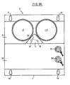
- FIGS. 3A and 3B show that, mechanically, a device D (one of the devices D1 to D4) comprises a base plate 1, on which is mounted a block of generally pyramidal shape, made of a synthetic material such as for example the two-component curing adhesive called araldite (registered trademark).
- araldite registered trademark
- the pyramid is doubly truncated. On one side, it is truncated at an intermediate level 21, where are provided orifices suitable for receiving the lamp bases L1 and L2, which are then mounted perpendicular to the flat face 1. At the top, the pyramid is truncated at one level upper 22, where terminals B1 and B2 appear which will be found later.
- this column 3 Between the two lamps L1 and L2, for example on the intermediate level 21, is mounted a column 3, pluggable electrically and mechanically by studs such as 31 and 32 on the block 2.
- this column 3 On the side of the lamp L1, this column 3 houses a photodetector 30, which is brought into contact with the illuminating part of this lamp. The mounting is preferably carried out so that this detector is very insensitive to other ambient light sources which may arise.
- the base plate 1 includes, for example at an angle, bean-shaped fixing holes such as 11, 12, 13 and 14.
- the lamps L1 and L2 are for example fluorescent lamps of the type with ballast and incorporated regulator, such as the lamps known in France under the name "Fairy". It turned out that a single 9 watt lamp could be enough to light a standardized airport box.
- FIG. 4 shows the electrical diagram of a device D according to the invention.
- the terminals B1 and B2 are terminals leading to the primary winding P of a current transformer TC, with its magnetic circuit CM.
- This primary winding S first receives in parallel a capacitor 50. This is followed in parallel by two high-voltage clipping diodes mounted head to tail, 51 and 52.
- this inverter I In its rest position, this inverter I closes the circuit on a lamp L1. In its working position, it closes it on the L2 lamp.
- the lamp L1 receives in parallel a resistance R10 of high value. And it is coupled to the photodetector 30 already mentioned.
- An auxiliary secondary winding SA provided in parallel with a surge suppressor 70, supplies a rectifier bridge 80, the outputs of which are provided in parallel with filtering produced by capacitor 91 and resistor 92.
- the output of this is used to supply an electronic control assembly, the input of which is defined by the photodetector 30.
- This one which is here phototransistor, has its collector connected to the positive terminal by a resistor 101, while its emitter joins the base of a transistor 102 whose emitter is grounded and whose collector joins the positive line by resistance 103.
- a first time constant is defined on the output of transistor 102 by resistor 104 and capacitor 10.7.
- the resistor 104 In parallel on the resistor 104 are mounted in series a diode 105 and a resistor 106, the cathode of the diode being on the side of the collector of the transistor 102.
- the resistor 104 is of significantly higher value than the resistor 106. This allows, when the phototransistor 30 finds that the lamp L1 does not light up, this information is inhibited for a time corresponding to a time at least equal to the nominal duration of ignition of the lamp. In practice, the ignition time of a lamp of this kind being approximately 2 seconds, the time constant applied to the detection is of the order of 10 seconds for example.
- the voltage available across the capacitor 107 rises, to be transmitted through a threshold device 108 consisting for example of a Zener diode at a Darlington power stage 110.
- a threshold device 108 consisting for example of a Zener diode at a Darlington power stage 110.
- This actuates via a resistor 111 a relay 120, which receives in parallel a capacitor 112.
- the relay 120 changes the state of the switch I, at the same time as '' it closes a contact 121, which ensures the self-maintenance of the relay.
- the tilting of the inverter has the effect of using the lamp L2, in place of the lamp L1.
- the terminals B1 and B2 of the current transformer are supplied by an effective current of 6.6 Amperes.
- Secondary S supplies the nominal current of the lamp used (9 watts or 18 watts in the examples concerned) at a voltage of approximately 220 volts.
- This corresponds to a current transformer having a high transformation ratio, of the order of about 70, note that if the value of the effective primary current is varied, this value being able to be modified by about 20%, this transformation ratio will vary.
- the power of the transformer is between 10 and 100 VA, preferably between 20 and 50 VA.
- lamps comprising a fluorescent tube and its supply members, integrated in the same glass, while retaining satisfactory operation.
- the invention thus makes it possible to improve the reliability of lighting the light boxes, while reducing their electrical consumption for equivalent lighting (we go from twice 45 VA to 20 VA).
- a secondary advantage is the reduction of the power of the emergency unit necessary to supply all the caissons of an airport, when the public electrical network does not work.
- the boxes Ci1 to CI4 equipped with the devices according to the invention are provided in a suitable number to correspond to the operating voltage of the low voltage secondary SBT of the medium voltage / low voltage transformer.
- the device according to the invention therefore functions like those of the prior art, which is another advantage.
Landscapes
- Circuit Arrangement For Electric Light Sources In General (AREA)
- Circuit Arrangements For Discharge Lamps (AREA)
Claims (10)
Applications Claiming Priority (2)
| Application Number | Priority Date | Filing Date | Title |
|---|---|---|---|
| FR8503313 | 1985-03-06 | ||
| FR8503313A FR2578708B1 (fr) | 1985-03-06 | 1985-03-06 | Circuit electrique de dispositif d'eclairage, notamment pour caisson indicateur d'aeroport |
Publications (2)
| Publication Number | Publication Date |
|---|---|
| EP0196249A1 EP0196249A1 (de) | 1986-10-01 |
| EP0196249B1 true EP0196249B1 (de) | 1990-01-17 |
Family
ID=9316935
Family Applications (1)
| Application Number | Title | Priority Date | Filing Date |
|---|---|---|---|
| EP19860400463 Expired - Lifetime EP0196249B1 (de) | 1985-03-06 | 1986-03-05 | Beleuchtungseinrichtung, insbesondere für wasserdichten Flugplatzkasten |
Country Status (3)
| Country | Link |
|---|---|
| EP (1) | EP0196249B1 (de) |
| DE (1) | DE3668405D1 (de) |
| FR (1) | FR2578708B1 (de) |
Cited By (1)
| Publication number | Priority date | Publication date | Assignee | Title |
|---|---|---|---|---|
| US7768284B2 (en) | 2004-02-16 | 2010-08-03 | Infineon Technologies Ag | Test apparatus for testing a semiconductor device, and method for testing the semiconductor device |
Families Citing this family (2)
| Publication number | Priority date | Publication date | Assignee | Title |
|---|---|---|---|---|
| GB2341017B (en) * | 1998-08-25 | 2003-04-30 | George Alan Limpkin | Improvements in lighting |
| FR2812757B1 (fr) | 2000-08-04 | 2002-12-06 | Augier S A | Systeme de balisage a isolation et etancheite renforcee de piste et bloc de transformateurs utilise |
Family Cites Families (3)
| Publication number | Priority date | Publication date | Assignee | Title |
|---|---|---|---|---|
| DE2829135C2 (de) * | 1978-07-03 | 1982-09-02 | Siemens AG, 1000 Berlin und 8000 München | Überwachungseinrichtung für den Lampenausfall bei einer Flugplatzbefeuerung |
| DE3005887A1 (de) * | 1980-02-16 | 1981-09-03 | Wilfried 2080 Pinneberg Rubach | Anordnung bei elektrischen anlagen, insbesondere leuchttransparent o.dgl. |
| DE3121311A1 (de) * | 1981-05-29 | 1983-01-27 | Licentia Patent-Verwaltungs-Gmbh, 6000 Frankfurt | Verfahren zur ermittlung der ausfallkennlinie eines lampenkreises und schaltungsanordnung zur durchfuehrung des verfahrens |
-
1985
- 1985-03-06 FR FR8503313A patent/FR2578708B1/fr not_active Expired
-
1986
- 1986-03-05 EP EP19860400463 patent/EP0196249B1/de not_active Expired - Lifetime
- 1986-03-05 DE DE8686400463T patent/DE3668405D1/de not_active Expired - Fee Related
Cited By (1)
| Publication number | Priority date | Publication date | Assignee | Title |
|---|---|---|---|---|
| US7768284B2 (en) | 2004-02-16 | 2010-08-03 | Infineon Technologies Ag | Test apparatus for testing a semiconductor device, and method for testing the semiconductor device |
Also Published As
| Publication number | Publication date |
|---|---|
| DE3668405D1 (de) | 1990-02-22 |
| FR2578708B1 (fr) | 1987-03-27 |
| FR2578708A1 (fr) | 1986-09-12 |
| EP0196249A1 (de) | 1986-10-01 |
Similar Documents
| Publication | Publication Date | Title |
|---|---|---|
| US5508589A (en) | Power saving voltage reduction system for high intensity discharge lighting systems | |
| FR2881914A1 (fr) | Bloc de commande d'eclairage destine a un appareil d'eclairage de vehicule | |
| FR2527409A1 (fr) | Dispositif pour la detection a distance d'une lampe grillee dans une installation d'eclairage avec une pluralite de lampes en parallele | |
| FR2867624A1 (fr) | Dispositif d'eclairage avec fonction d'eclairage de secours | |
| EP0196249B1 (de) | Beleuchtungseinrichtung, insbesondere für wasserdichten Flugplatzkasten | |
| FR2516335A1 (fr) | Dispositif de commande de l'intensite lumineuse d'un tube fluorescent alimente sur une tension continue | |
| FR2711884A1 (fr) | Dispositif de signalisation notamment pour la signalisation routière, aéronautique ou maritime. | |
| FR2681754A1 (fr) | Installation d'eclairage electrique et procede de commande et de surveillance de ladite installation. | |
| FR2581488A1 (fr) | Perfectionnement aux alimentations en courant alternatif non susceptibles d'etre interrompues | |
| EP0025404B1 (de) | Kurzschlusselement für Serienschaltung | |
| FR2532809A1 (fr) | Montage de diodes | |
| LU81054A1 (fr) | Dispositif d'alimentation sur deux niveaux de pissance pour lampes fluorescentes et installation d'eclairage comprtant un tel dispositif | |
| FR2946828A1 (fr) | Systeme d'eclairage de securite. | |
| FR2617634A1 (fr) | Dispositif de commande et de controle de contacteur, et procede de controle correspondant | |
| EP2887772B1 (de) | Beleuchtungssystem mit Leuchtdioden, und Leuchte für die Fernbeleuchtung | |
| EP2887769B1 (de) | Beleuchtungssystem mit Leuchtdioden, und Leuchte für die Fernbeleuchtung | |
| FR2757708A1 (fr) | Appareil electrique comportant un dispositif de controle de charge | |
| FR2535930A1 (fr) | Ensemble portatif autonome pour le controle d'equipement d'eclairage public | |
| FR2646581A1 (fr) | Procede et dispositif de surveillance d'un element electrique tel qu'un point lumineux | |
| FR3015174B1 (fr) | Systeme d'eclairage a diodes electroluminescentes et luminaire distant | |
| FR2616929A1 (fr) | Dispositif de commande de test d'autonomie pour un ensemble de blocs d'eclairage de securite | |
| FR2743975A1 (fr) | Circuit electronique d'alimentation et de controle de ballast pour lampes d'eclairement | |
| FR2952765A1 (fr) | Interrupteur variateur electronique perfectionne | |
| JPS5821519Y2 (ja) | 放電灯用防災灯 | |
| FR2755801A1 (fr) | Bloc autonome d'eclairage de securite perfectionne |
Legal Events
| Date | Code | Title | Description |
|---|---|---|---|
| PUAI | Public reference made under article 153(3) epc to a published international application that has entered the european phase |
Free format text: ORIGINAL CODE: 0009012 |
|
| AK | Designated contracting states |
Kind code of ref document: A1 Designated state(s): BE DE GB |
|
| 17P | Request for examination filed |
Effective date: 19870325 |
|
| 17Q | First examination report despatched |
Effective date: 19890517 |
|
| GRAA | (expected) grant |
Free format text: ORIGINAL CODE: 0009210 |
|
| AK | Designated contracting states |
Kind code of ref document: B1 Designated state(s): BE DE GB |
|
| PG25 | Lapsed in a contracting state [announced via postgrant information from national office to epo] |
Ref country code: GB Effective date: 19900117 |
|
| REF | Corresponds to: |
Ref document number: 3668405 Country of ref document: DE Date of ref document: 19900222 |
|
| PG25 | Lapsed in a contracting state [announced via postgrant information from national office to epo] |
Ref country code: BE Effective date: 19900331 |
|
| GBV | Gb: ep patent (uk) treated as always having been void in accordance with gb section 77(7)/1977 [no translation filed] | ||
| BERE | Be: lapsed |
Owner name: ETS. AUGIER S.A. Effective date: 19900331 |
|
| PLBE | No opposition filed within time limit |
Free format text: ORIGINAL CODE: 0009261 |
|
| STAA | Information on the status of an ep patent application or granted ep patent |
Free format text: STATUS: NO OPPOSITION FILED WITHIN TIME LIMIT |
|
| PG25 | Lapsed in a contracting state [announced via postgrant information from national office to epo] |
Ref country code: DE Effective date: 19901201 |
|
| 26N | No opposition filed |