EP0195263B1 - Floor cleaner or floor treating machine - Google Patents
Floor cleaner or floor treating machine Download PDFInfo
- Publication number
- EP0195263B1 EP0195263B1 EP86102113A EP86102113A EP0195263B1 EP 0195263 B1 EP0195263 B1 EP 0195263B1 EP 86102113 A EP86102113 A EP 86102113A EP 86102113 A EP86102113 A EP 86102113A EP 0195263 B1 EP0195263 B1 EP 0195263B1
- Authority
- EP
- European Patent Office
- Prior art keywords
- wheel
- motor
- rotation
- driving wheel
- axis
- Prior art date
- Legal status (The legal status is an assumption and is not a legal conclusion. Google has not performed a legal analysis and makes no representation as to the accuracy of the status listed.)
- Expired
Links
- 230000005540 biological transmission Effects 0.000 claims abstract description 12
- 238000004140 cleaning Methods 0.000 claims abstract description 11
- 230000006835 compression Effects 0.000 claims description 3
- 238000007906 compression Methods 0.000 claims description 3
- 230000000630 rising effect Effects 0.000 claims description 2
- 238000006073 displacement reaction Methods 0.000 claims 1
- 230000002093 peripheral effect Effects 0.000 claims 1
- 230000001419 dependent effect Effects 0.000 description 3
- 238000005096 rolling process Methods 0.000 description 2
- 239000006096 absorbing agent Substances 0.000 description 1
- 230000007812 deficiency Effects 0.000 description 1
- 230000003993 interaction Effects 0.000 description 1
- 238000005498 polishing Methods 0.000 description 1
- 230000036316 preload Effects 0.000 description 1
- 230000035939 shock Effects 0.000 description 1
- 238000001228 spectrum Methods 0.000 description 1
- 238000003971 tillage Methods 0.000 description 1
- 210000002268 wool Anatomy 0.000 description 1
Images


Classifications
-
- A—HUMAN NECESSITIES
- A47—FURNITURE; DOMESTIC ARTICLES OR APPLIANCES; COFFEE MILLS; SPICE MILLS; SUCTION CLEANERS IN GENERAL
- A47L—DOMESTIC WASHING OR CLEANING; SUCTION CLEANERS IN GENERAL
- A47L11/00—Machines for cleaning floors, carpets, furniture, walls, or wall coverings
- A47L11/40—Parts or details of machines not provided for in groups A47L11/02 - A47L11/38, or not restricted to one of these groups, e.g. handles, arrangements of switches, skirts, buffers, levers
-
- A—HUMAN NECESSITIES
- A47—FURNITURE; DOMESTIC ARTICLES OR APPLIANCES; COFFEE MILLS; SPICE MILLS; SUCTION CLEANERS IN GENERAL
- A47L—DOMESTIC WASHING OR CLEANING; SUCTION CLEANERS IN GENERAL
- A47L11/00—Machines for cleaning floors, carpets, furniture, walls, or wall coverings
- A47L11/02—Floor surfacing or polishing machines
- A47L11/10—Floor surfacing or polishing machines motor-driven
- A47L11/14—Floor surfacing or polishing machines motor-driven with rotating tools
- A47L11/16—Floor surfacing or polishing machines motor-driven with rotating tools the tools being disc brushes
-
- A—HUMAN NECESSITIES
- A47—FURNITURE; DOMESTIC ARTICLES OR APPLIANCES; COFFEE MILLS; SPICE MILLS; SUCTION CLEANERS IN GENERAL
- A47L—DOMESTIC WASHING OR CLEANING; SUCTION CLEANERS IN GENERAL
- A47L11/00—Machines for cleaning floors, carpets, furniture, walls, or wall coverings
- A47L11/40—Parts or details of machines not provided for in groups A47L11/02 - A47L11/38, or not restricted to one of these groups, e.g. handles, arrangements of switches, skirts, buffers, levers
- A47L11/4036—Parts or details of the surface treating tools
- A47L11/4038—Disk shaped surface treating tools
-
- A—HUMAN NECESSITIES
- A47—FURNITURE; DOMESTIC ARTICLES OR APPLIANCES; COFFEE MILLS; SPICE MILLS; SUCTION CLEANERS IN GENERAL
- A47L—DOMESTIC WASHING OR CLEANING; SUCTION CLEANERS IN GENERAL
- A47L11/00—Machines for cleaning floors, carpets, furniture, walls, or wall coverings
- A47L11/40—Parts or details of machines not provided for in groups A47L11/02 - A47L11/38, or not restricted to one of these groups, e.g. handles, arrangements of switches, skirts, buffers, levers
- A47L11/4063—Driving means; Transmission means therefor
- A47L11/4069—Driving or transmission means for the cleaning tools
Definitions
- the present invention relates to a floor cleaning or processing machine according to the preamble of claim 1.
- Such a floor cleaning or processing machine is known from US-A 2 870 468.
- the gear train between the motor and the holder has only the friction gear, which has a cylindrical drive wheel coupled to the motor via a flexible shaft, which cooperates with a frustoconical friction ring as the driven wheel.
- the drive wheel can be lifted off the friction ring, so that the gear train is interrupted, i. H. that the bracket is no longer powered.
- the reduction ratio of the friction gear of the known machine is constant, so that the holder is given a speed which - if neglect of any slippage - is directly proportional to the speed of the electric motor.
- the efficiency of the friction gear transmission also depends, among other things, on the contact pressure with which the drive wheel and the driven wheel interact. It is known per se from DE-A 2 219 238 to change this contact pressure automatically in accordance with the torque to be transmitted.
- Dependent claim 5 describes a preferred embodiment of the proposed tillage machine, in which the contact pressure between the drive and driven wheels is changed automatically and in a torque-dependent manner.
- the floor cleaning machine 10 shown in Fig. 1 has a base frame 11, on which an operating and control drawbar 12 is pivoted by means not shown by a limited pivot angle.
- An essentially circular, downwardly projecting flange 13 is integrally formed on the base frame 11, which surrounds a cleaning tool, here a disk brush 14, with play.
- the disk brush 14 is non-rotatably fixed, but can be exchanged for a cleaning tool of a different kind on the underside of a mounting disk 15, which is in turn rotatably supported by a ball bearing 16 on a stub shaft 17 anchored to the base frame 18 and projecting downward.
- An externally toothed toothed ring 18, with which a pinion 19 meshes, is attached to the top of the mounting disk 15.
- the reduction ratio between the pinion 19 and the toothed ring 18 is, for example, 1: 8.
- the pinion is seated on a wool 21 which is rotatably mounted in a ball bearing 20 and penetrates the base frame 11.
- a flat friction disk 22 is seated on the end of the shaft 21 which pierces the base frame 11 holding the driven gear of a friction gear bes 23 forms, the drive wheel is designated 24 and which - as will be described later - is coupled to the shaft of an electric motor 25.
- the friction wheel gear 23 and the reduction gear pinion 19 / toothed ring 18 thus form the gear train between the motor 25 and the holding disk 15.
- the motor 25 and with it the drive wheel 24 are guided in the direction of the axis of rotation 21 of the pinion 19 and can be moved away from it by means of rollers 27 running on rails 26 arranged on both sides of the motor housing.
- the rails 26 are components of an auxiliary frame 28, which in turn can be tilted by a limited tilt angle 29 (FIG. 3) about an axis 30 carried by a frame 31.
- the frame 31 is anchored on the base frame 11.
- a first return spring 32 which interacts with a shock absorber 33, holds the auxiliary frame 28 when the motor 25 is at a standstill in the tilted position in which the shaft of the motor 25 has the direction indicated by the solid line 34 in FIG. 3.
- the bias of this first return spring 32 is adjustable and lockable for a purpose to be described.
- a second return spring 35 strives to keep the motor 25 and with it the drive wheel 24 the farthest away from the shaft 21 of the pinion 19.
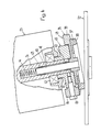
- the output wheel 22 with its flat friction surface, the motor 25 with its shaft 36 mounted in a ball bearing 42 and the drive wheel 24 can be seen schematically.
- the drive wheel 24 has an essentially annular friction lining 37, the one with the friction surface 38 in contact with the driven wheel 22 has the shape of a flat truncated cone.
- the friction lining 37 is firmly anchored to a carrier disk 39, which in turn is seated in a rotationally fixed manner at the end of a shaft 40.
- the shaft 40 arranged coaxially to the motor shaft 36 extends into a bore 41 machined in the motor shaft 36 and is mounted in the motor shaft 36 by means of bearing bushes (43), as will be shown, to a limited degree of rotation and axially displaceably.
- a compression spring 44 acts on the end of the shaft 40 remote from the carrier disk 39 and thus urges the carrier disk 39 and with it the friction lining 37 in contact with the driven gear 22.
- FIG. 4 also shows that on the projecting end of the motor shaft 36 there is anchored a transmission part, generally designated 45, which cooperates with the side of the carrier disk 39 facing away from the friction lining 37.
- This transmission part 45 has - as can also be seen in FIGS. 5 and 6 - a plurality (in the present case its five) rollers 46 which are arranged at regular circumferential intervals and are freely rotatable about axes projecting essentially at right angles from the shafts 36, 40 which axes are formed by stepped bolts 48 screwed into the base body 47 of the transmission part 45.
- stepped bolts 48 screwed into the base body 47 of the transmission part 45.
- the rollers 46 can be formed by the outer race itself of a ball bearing.
- the rollers 46 interact with an annular cam track 49 formed on the side of the carrier disk 39 facing away from the friction lining 37.
- the cam track 49 has as many depressions as there are rollers 46, ramps 50, 51 rising in a wedge shape adjoining them on both sides of the depressions.
- the power transmitted by the friction gear 23 can be adapted to the nominal power of the motor 25. If this pretension is increased, the tilting of the motor 25 cannot be prevented during start-up, but the contact pressure of the friction surface 38 on the driven wheel 22 increases and thereby the transmissible torque which ultimately depends on the permissible output of the motor 23.
- the second return spring 35 serves to remove the drive wheel 24 from the center of the driven wheel 22 again after the motor 25 has been switched off, so that when the motor is switched on again, the driven wheel 22 is first gently at the lowest speed (corresponding, for example, about 140 rpm .
- the brush 14) can start and the speed increases only afterwards in accordance with the braking torque to be overcome.
- This return of the switched-off motor 25 by the second return spring 35 is facilitated in that the frictional engagement between the friction lining 37 and the driven wheel 22 only originates from the compression spring 44, while the interaction of the rollers 46 with the cam track 49 ceases.
Landscapes
- Friction Gearing (AREA)
- Devices For Executing Special Programs (AREA)
- Vehicle Cleaning, Maintenance, Repair, Refitting, And Outriggers (AREA)
- Disintegrating Or Milling (AREA)
- Motorcycle And Bicycle Frame (AREA)
- Electric Propulsion And Braking For Vehicles (AREA)
- Brushes (AREA)
Abstract
Description
Die vorliegende Erfindung betrifft eine Bodenreinigungs- oder -bearbeitungsmaschine nach dem Oberbegriff des Patentanspruches 1.The present invention relates to a floor cleaning or processing machine according to the preamble of claim 1.
Eine solche Bodenreinigungs- oder -bearbeitungsmaschine ist aus der US-A 2 870 468 bekannt. Bei der bekannten Maschine weist der Getriebezug zwischen dem Motor und der Halterung nur das Reibradgetriebe auf, das ein über eine flexible Welle an den Motor gekoppeltes zylindrisches Antriebsrad aufweist, das mit einem kegelstumpfförmigen Reibkranz als Abtriebsrad zusammenwirkt. Das Antriebsrad ist vom Reibkranz abhebbar, so dass der Getriebezug unterbrochen ist, d. h. dass die Halterung nicht mehr angetrieben ist. Im übrigen aber ist das Untersetzungsverhältnis des Reibradgetriebes der bekannten Maschine konstant, so dass der Halterung eine Drehzahl erteilt wird, die - bei Vemachlässigung eines allfälligen Schlupfes - direkt proportional zur Drehzahl des Elektromotors ist.Such a floor cleaning or processing machine is known from US-A 2 870 468. In the known machine, the gear train between the motor and the holder has only the friction gear, which has a cylindrical drive wheel coupled to the motor via a flexible shaft, which cooperates with a frustoconical friction ring as the driven wheel. The drive wheel can be lifted off the friction ring, so that the gear train is interrupted, i. H. that the bracket is no longer powered. For the rest, however, the reduction ratio of the friction gear of the known machine is constant, so that the holder is given a speed which - if neglect of any slippage - is directly proportional to the speed of the electric motor.
Je nach gewünschter Arbeitsoperation können an der Halterung einer solchen Maschine verschiedene Reinigungs- bzw. Bearbeitungswerkzeuge, beispielsweise Scheibenbürsten verschiedener Härtegrade, Polierscheiben oder gar Schleifteller befestigt werden. Für jedes dieser Werkzeuge existiert erfahrungsgemäss ein für die durchzuführende Arbeitsoperation optimaler Drehzahlbereich, wobei diese Drehzahlbereiche unterschiedlich sind.Depending on the desired work operation, various cleaning or processing tools, for example disc brushes of different degrees of hardness, polishing discs or even grinding plates, can be attached to the holder of such a machine. Experience has shown that for each of these tools there is an optimum speed range for the work operation to be carried out, these speed ranges being different.
Dazu kommt allerdings die Oberflächenbeschaffenheit des zu reinigenden bzw. zu bearbeitenden Bodens, welche, zusammen mit dem gerade verwendeten Werkzeug massgebend ist für das vom Motor zu überwindende Bremsmoment bzw. für das an der Halterung abgenommene Drehmoment. Die eingangs genannte bekannte Maschine hat eine einzige Arbeitsdrehzahl und ist daher nur für eine Gattung von Operationen geeignet und kann somit nicht das gesamte Spektrum der gewünschten Arbeitsoperationen optimal bewältigen.In addition, however, there is the surface condition of the floor to be cleaned or worked, which, together with the tool just used, is decisive for the braking torque to be overcome by the motor or for the torque taken off on the holder. The known machine mentioned at the beginning has a single working speed and is therefore only suitable for one type of operation and therefore cannot optimally cope with the entire spectrum of the desired working operations.
Um diesem Mangel zu begegnen, und auch um Ueberlastungen des Motors oder des diesen speisenden Netzanschlusses zu vermeiden, ist auch schon vorgeschlagen worden, in den Getriebezug zwischen Motor und Halterung ein beispielsweise zweistufiges Schaltgetriebe einzubauen, oder einen polumschaltbaren Motor vorzusehen.In order to counteract this deficiency, and also to avoid overloading the motor or the mains connection feeding it, it has also been proposed to install, for example, a two-stage manual transmission in the gear train between the motor and the holder, or to provide a pole-changing motor.
Diese Lösung vermag jedoch nicht zu befriedigen, denn - abgesehen von der komplizierteren Handhabung - bieten solche Maschinen lediglich zwei verhältnismässig eng begrenzte Drehzahlbereiche der Halterung, wobei zugleich Ueberlastungen des Motors nicht vollständig ausgeschlossen sind.However, this solution is unsatisfactory, because - apart from the more complicated handling - such machines only offer two relatively narrowly limited speed ranges of the holder, at the same time overloading the motor is not completely excluded.
Es ist daher ein Zweck der Erfindung, eine Maschine der eingangs genannten Art zu schaffen, bei der die Leistungsaufnahme des Elektromotors im wesentlichen konstant ist, wobei sich jedoch die Drehzahl der Halterung selbsttätig den Gegebenheiten (Reinigungs- bzw. Bearbeitungswerkzeug, Oberflächenbeschaffenheit des Bodens) anpasst.It is therefore a purpose of the invention to create a machine of the type mentioned in the introduction, in which the power consumption of the electric motor is essentially constant, but the speed of the holder automatically adapts to the circumstances (cleaning or processing tool, surface quality of the floor) .
Zu diesem Zweck weist die vorgeschlagene Maschine die im Kennzeichen des Patentanspruches 1 definierten Merkmale auf.For this purpose, the proposed machine has the features defined in the characterizing part of patent claim 1.
Merkmale bevorzugter Ausführungsformen sind in den abhängigen Ansprüchen definiert.Features of preferred embodiments are defined in the dependent claims.
Dabei ist zu bemerken, dass der Wirkungsgrad des Reibradgetriebes unter anderem auch davon abhängig ist, mit welcher Anpresskraft das Antriebsrad und das Abtriebsrad zusammenwirken. An sich ist es aus der DE-A 2 219 238 bekannt, diese Anpresskraft selbsttätig nach Massgabe des zu übertragenden Drehmomentes zu verändem. Im abhängigen Anspruch 5 ist eine bevorzugte Ausführungsform der vorgeschlagenen Bodenbearbeitungsmaschine umschrieben, bei der die Anpresskraft zwischen Antriebs- und Abtriebsrad selbsttätig und drehmomentabhängig verändert wird.It should be noted here that the efficiency of the friction gear transmission also depends, among other things, on the contact pressure with which the drive wheel and the driven wheel interact. It is known per se from DE-A 2 219 238 to change this contact pressure automatically in accordance with the torque to be transmitted. Dependent claim 5 describes a preferred embodiment of the proposed tillage machine, in which the contact pressure between the drive and driven wheels is changed automatically and in a torque-dependent manner.
Ein Ausführungsbeispiel des Erfindungsgegenstandes ist nachstehend anhand der Zeichnung näher beschrieben. Es zeigt:
- Fig. 1 - einen schematischen Vertikalschnitt durch eine Bodenreinigungsmaschine ;
- Fig. 2 eine schematische Draufsicht auf Fig. 1 unter Weglassung der Abdeckung.
- Fig. 3 eine schematische Stirnansicht der Fig. 1, wobei die Frontseite der Abdeckung weggebrochen ist,
- Fig. 4 in grösserem Massstab die wesentlichen Teile des Reibradgetriebes, und
- Fig. 5 und 6 in schematischer Draufsicht bzw. Seitenansicht die Elemente, die die Welle des Motors an jene des Antriebsrades des Reibradgetriebes koppeln.
- Fig. 1 - a schematic vertical section through a floor cleaning machine;
- Fig. 2 is a schematic plan view of Fig. 1 with the cover omitted.
- 3 is a schematic end view of FIG. 1, with the front of the cover broken away,
- Fig. 4 on a larger scale, the essential parts of the friction gear, and
- 5 and 6 in a schematic plan view and side view of the elements which couple the shaft of the motor to that of the drive wheel of the friction gear.
Die in Fig. 1 dargestellte Bodenreinigungsmaschine 10 besitzt einen Grundrahmen 11, am den eine Bedienungs- und Steuerdeichsel 12 durch nicht dargestellte Mittel um einen beschränkten Schwenkwinkel schwenkbar angelenkt ist. Am Grundrahmen 11 ist ein im wesentlichen kreisrunder, nach unten abstehender Flansch 13 angeformt, der ein Reinigungswerkzeug, hier eine Scheibenbürste 14, mit Spiel umgreift. Die Scheibenbürste 14 ist auf nicht' näher dargestellte Weise drehfest, jedoch gegen ein Reinigungswerkzeug anderer Art austauschbar an der Unterseite einer Halterungsscheibe 15 befestigt, die ihrerseits über ein Kugellager 16 drehbar auf einer am Grundrahmen 18 verankerten, nach unten abstehenden Stummelwelle 17 gelagert ist. Auf der Oberseite der Halterungsscheibe 15 ist ein aussenverzahnter Zahnring 18 befestigt, mit dem ein Ritzel 19 kämmt. Das Untersetzungsverhältnis zwischen dem Ritzel 19 und dem Zahnring 18 beträgt beispielsweise 1 : 8. Das Ritzel sitzt auf einer in einem Kugelleger 20 drehbar gelagerten und den Grundrahmen 11 durchsetzenden Wolle 21. Auf dem den Grundrahmen 11 durchstossenden Ende der Welle 21 sitzt eine ebene Reibscheibe 22, die das Abtriebsrad eines Reibrad-Getriebes 23 bildet, dessen Antriebsrad mit 24 bezeichnet ist und das - wie noch zu beschreiben sein wird - an die Welle eines Elektromotors 25 gekoppelt ist. Das Reibrad-Getriebe 23 sowie die _ Untersetzungsstufe Ritzel 19/Zahnring 18 bilden somit den Getriebezug zwischen dem Motor 25 und der Halterungsscheibe 15.The
Der Motor 25 und mit ihm das Antriebsrad 24 sind mittels auf beidseits des Motorgehäuses angeordneten Schienen 26 laufenden Rollen 27 in Richtung zur Drehachse 21 des Ritzels 19 hin und von dieser weg verschiebbar geführt. Die Schienen 26 sind Bestandteile eines Hilfsrahmens 28, der seinerseits um einen beschränkten Kippwinkel 29 (Fig. 3) um eine von einem Gestell 31 getragene Achse 30 kippbar ist. Das Gestell 31 ist auf dem Grundrahmen 11 verankert. Eine erste Rückholfeder 32, die mit einem Stossdämpfer 33 zusammenwirkt, hält das Hilfsgestell 28 beim Stillstand des Motors 25 in jener Kipplage, in der die Welle des Motors 25 die mit der ausgezogenen Linie 34 in Fig. 3 angedeutete Richtung hat. Die Vorspannung dieser ersten Rückholfeder 32 ist zu einem noch zu beschreibenden Zwecke verstellbar und feststellbar. Eine zweite Rückholfeder 35 ist bestrebt, den Motor 25 und mit ihm das Antriebsrad 24 am weitesten weg von der Welle 21 des Ritzels 19 zu halten.The
Betrachtet man nun Fig. 4, so erkennt man schematisch das Abtriebsrad 22 mit seiner ebenen Reibfläche, den Motor 25 mit seiner in einem Kugellager 42 gelagerten Welle 36 und das Antriebsrad 24. Das Antriebsrad 24 weist einen im wesentlichen ringförmigen Reibbelag 37 auf, dessen mit dem Abtriebsrad 22 in Berührung stehende Reibfläche 38 die Form eines flachen Kegelstumpfes aufweist. Der Reibbelag 37 ist fest an einer Trägerscheibe 39 verankert, die ihrerseits drehfest am Ende einer Welle 40 sitzt. Die koaxial zur Motorwelle 36 angeordnete Welle 40 erstreckt sich in eine in der Motorwelle 36 eingearbeitete Bohrung 41 und ist mittels Lagerbüchsen (43) in der Motorwelle 36 - wie sich noch zeigen wird - beschränkt verdrehbar sowie axial verschiebbar gelagert. Eine Druckfeder 44 wirkt auf das von der Trägerscheibe 39 entfernte Ende der Welle 40 und drängt somit die Trägerscheibe 39 und mit ihr den Reibbelag 37 in Kontakt mit dem Abtriebsrad 22.4, the
Der Fig. 4 ist ferner zu entnehmen, dass auf dem abstehenden Ende der Motorwelle 36 ein gesamthaft mit der Bezugsziffer 45 bezeichneter Uebertragungsteil verankert ist, der mit der dem Reibbelag 37 abgekehrten Seite der Trägerscheibe 39 zusammenwirkt. Dieser Uebertragungsteil 45 weist - wie auch den Fig. 5 und 6 zu entnehmen ist - mehrere (im vorliegenden Falle deren fünf) Rollen 46 auf, die in regelmässigen Umfangsabständen angeordnet sind und frei drehbar um in wesentlichen rechtwinklig von den Wellen 36, 40 abstehenden Achsen gelagert sind, welche Achsen durch in den Grundkörper 47 des Uebertragungsteils 45 eingeschraubte Stufenbolzen 48 gebildet sind. Der Einfachheit halber sind Kugellager bzw. Lagerbüchsen, mit denen die Rollen 46 auf den Stufenbolzen 48 gelagert sind, nicht dargestellt. Beispielsweise können die Rollen 46 durch äusseren Laufring selbst eines Kugellagers gebildet sein.FIG. 4 also shows that on the projecting end of the
Die Rollen 46 wirken mit einer auf der dem Reibbelag 37 abgekehrten Seite der Trägerscheibe 39 an dieser angeformten, kreisringförmigen Kurvenbahn 49 zusammen. Wie der Fig. 6 zu entnehmen ist, weist die Kurvenbahn 49 ebensoviele Vertiefungen auf, als Rollen 46 vorhanden sind, wobei zu beiden Seiten der Vertiefungen keilförmig ansteigende Rampen 50, 51 an diese anschliessen. Wenn nun die Motorwelle 36, und damit der Uebertragungsteil 45 beispielsweise im Sinne des Pfeiles 52 in Fig. 6 zu laufen beginnt, wird der Uebertragungsteil 45 je nach Trägheit des Antriebsrades 24 und dem auf dieses durch das Abtriebsrad 22 ausgeübte Bremsmoment etwas voreilen, was - durch das Auflaufen der Rollen 46 auf die Rampen 50 - eine zusätzliche Erhöhung der in Richtung des Pfeiles 53 (Fig. 6) wirkenden Kraft bewirkt, mit der die Reibfläche 38 an das Abtriebsrad 22 gedrückt wird und somit einer Erhöhung des Reibschlusses gleichkommt. Sihngemäss dasselbe gilt, wenn der Motor entgegen der Richtung des Pfeiles 52 anläuft.The
Es wurde bereits dargelegt und es ist in Fig. 3 angedeutet, dass im Stillstand die Welle des Motors 25 und damit auch die Achse des Antriebsrades 24 die mit der Linie 34 angedeutete Richtung hat. Läuft der Motor 25 nun in Richtung des Pfeiles 54 an, wird die Trägheit des Abtriebsrades 22 mit den formschlüssig mit diesem verbundenen Teilen 14, 15, 18 und 19 und das von diesen Teilen ausgehende Bremsmoment bewirken, dass der Motor und die mit dessen Welle 36 koaxial verbundenen Teile 40, 24 und 45 gegen die Wirkung der ersten Rückholfeder 32 um die Kippachse 30 kippen, bis die Achsen des Motors 25 und der damit verbundenen Teile 40, 24, 25, die in Fig. 3 mit der Linie 55 angedeutete Richtung haben. Dies bedeutet aber, dass die Mantellinie, längs welcher die Reibfläche 38 die obere Seite des Abtriebsrades 22 berührt, weder im Stillstand noch im Lauf mit einem Radius des Abtriebsrades 22 zusammenfällt, weil die Achsen der mit der Motorwelle 36 koaxialen Teile windschief zur Drehachse des Abtriebsrades 22 verlaufen. Dies hat wiederum zur Folge, dass das Antriebsrad 24 im Lauf nicht eine reine (wenn auch gegebenenfalls mit Schlupf behaftete) Abwälzbewegung auf dem (laufenden) Abtriebsrad 22 ausführt, sondern neben der Abwälzbewegung auch eine « Radier »-Bewegung, die zur Folge hat, dass im Lauf das Antriebsrad 24 das Bestreben hat, gegen die Mitte des Abtriebsrades 22 zu laufen, was (bei konstanter Drehzahl des Antriebsmotors 24) eine Erhöhung der Drehzahl des Abtriebsrades 22 unter Verminderung des von diesem abnehmbaren Drehmomentes zur Folge hat.It has already been explained and it is indicated in FIG. 3 that the shaft of the
Einer solchen Erhöhung der Drehzahl und Verminderung des abnehmbaren Drehmomentes steht aber das von der Bürste 14 zu überwindende Bremsmoment entgegen, das auf das Abtriebsrad 22 übertragen wird. Dies wiederum hat zunächst zur Folge, dass - wie beschrieben - der Anpressdruck der Reibfläche 38 auf das Abtriebsrad 22 und damit der Reibschluss zwischen diesen Teilen erhöht wird. Im Lauf ergibt sich sodann selbsttätig eine Art Gleichgewichtszustand, in dem stets die Drehzahl der Bürste 14 und damit das von dieser aufzubringende Drehmoment optimal und selbsttätig an die zu bearbeitende bzw. zu reinigende Oberfläche angepasst wird, wobei das vom Motor 25 abgenommene Drehmoment bzw. die vom Motor aufgenommene Leistung konstant bleibt.Such an increase in the speed and reduction in the removable torque is, however, opposed by the braking torque to be overcome by the
Durch Aenderung der Vorspannung der ersten Rückholfeder 32 kann die vom Reibradgetriebe 23 übertragene Leistung der Nennleistung des Motors 25 angepasst werden. Wird diese Vorspannung erhöht, dann kann das Kippen des Motors 25 beim Anlauf nicht verhindert werden, aber es erhöht sich der Anpressdruck der Reibfläche 38 auf das Abtriebsrad 22 und dadurch das übertragbare Drehmoment, das letzlich von der zulässigen Leistung des Motors 23 abhängt. Dagegen dient die zweite Rückholfeder 35 dazu, nach dem Ausschalten des Motors 25 das Antriebsrad 24 von der Mitte des Abtriebsrades 22 wieder zu entfernen, damit beim Wiedereinschalten des Motors das Abtriebsrad 22 zunächst sanft mit der geringsten Drehzahl (entsprechend beispielsweise ca. 140 U/min. der Bürste 14) anlaufen kann und sich die Drehzahl erst danach nach Massgabe des zu überwindenden Bremsmomentes erhöht. Dieses Zurückholen des ausgeschalteten Motors 25 durch die zweite Rückholfeder 35 ist dadurch erleichtert, dass der Reibschluss zwischen dem Reibbelag 37 und dem Abtriebsrad 22 nur noch von der Druckfeder 44 ausgeht, während das Zusammenwirken der Rollen 46 mit der Kurvenbahn 49 dahinfällt.By changing the preload of the
Claims (7)
Priority Applications (1)
| Application Number | Priority Date | Filing Date | Title |
|---|---|---|---|
| AT86102113T ATE44223T1 (en) | 1985-03-20 | 1986-02-19 | FLOOR CLEANING OR TREATMENT MACHINE. |
Applications Claiming Priority (2)
| Application Number | Priority Date | Filing Date | Title |
|---|---|---|---|
| CH1239/85A CH665764A5 (en) | 1985-03-20 | 1985-03-20 | FLOOR CLEANING OR MACHINING MACHINE. |
| CH1239/85 | 1985-03-20 |
Publications (2)
| Publication Number | Publication Date |
|---|---|
| EP0195263A1 EP0195263A1 (en) | 1986-09-24 |
| EP0195263B1 true EP0195263B1 (en) | 1989-06-28 |
Family
ID=4205732
Family Applications (1)
| Application Number | Title | Priority Date | Filing Date |
|---|---|---|---|
| EP86102113A Expired EP0195263B1 (en) | 1985-03-20 | 1986-02-19 | Floor cleaner or floor treating machine |
Country Status (7)
| Country | Link |
|---|---|
| US (1) | US4651378A (en) |
| EP (1) | EP0195263B1 (en) |
| AT (1) | ATE44223T1 (en) |
| CA (1) | CA1257954A (en) |
| CH (1) | CH665764A5 (en) |
| DE (1) | DE3664102D1 (en) |
| FI (1) | FI83030C (en) |
Families Citing this family (3)
| Publication number | Priority date | Publication date | Assignee | Title |
|---|---|---|---|---|
| DE3570497D1 (en) * | 1984-09-06 | 1989-06-29 | Delta Ag | Friction wheel torque converter |
| US5177828A (en) * | 1991-08-20 | 1993-01-12 | Windsor Industries, Inc. | Missing pad detector for a floor polishing tool |
| US10582825B2 (en) * | 2016-10-06 | 2020-03-10 | Dean Paavola | Modular surface maintainer |
Family Cites Families (6)
| Publication number | Priority date | Publication date | Assignee | Title |
|---|---|---|---|---|
| NL41034C (en) * | 1935-06-04 | |||
| US2508411A (en) * | 1944-02-12 | 1950-05-23 | Hendrik W Lundquist | Floor machine |
| US2870468A (en) * | 1952-09-20 | 1959-01-27 | Rudolf Blik Electrische App N | Rotary cleaning brush attachment for suction cleaning devices |
| DE1550842A1 (en) * | 1966-11-02 | 1970-01-29 | Lein Dr Ing Johann | Adjusting gear for continuously adjustable gear |
| DE1937914A1 (en) * | 1969-07-25 | 1971-02-18 | Danhorst Ellen | Adjustable friction gear |
| DE2219238C3 (en) * | 1972-04-20 | 1975-07-24 | P.I.V. Antrieb Werner Reimers Kg, 6380 Bad Homburg | Device for generating variable contact forces in variable speed gears |
-
1985
- 1985-03-20 CH CH1239/85A patent/CH665764A5/en not_active IP Right Cessation
-
1986
- 1986-02-19 AT AT86102113T patent/ATE44223T1/en not_active IP Right Cessation
- 1986-02-19 DE DE8686102113T patent/DE3664102D1/en not_active Expired
- 1986-02-19 EP EP86102113A patent/EP0195263B1/en not_active Expired
- 1986-03-17 US US06/840,094 patent/US4651378A/en not_active Expired - Fee Related
- 1986-03-19 FI FI861158A patent/FI83030C/en not_active IP Right Cessation
- 1986-03-19 CA CA000504500A patent/CA1257954A/en not_active Expired
Also Published As
| Publication number | Publication date |
|---|---|
| DE3664102D1 (en) | 1989-08-03 |
| ATE44223T1 (en) | 1989-07-15 |
| FI861158A (en) | 1986-09-21 |
| CA1257954A (en) | 1989-08-01 |
| CH665764A5 (en) | 1988-06-15 |
| US4651378A (en) | 1987-03-24 |
| FI861158A0 (en) | 1986-03-19 |
| FI83030B (en) | 1991-02-15 |
| FI83030C (en) | 1991-05-27 |
| EP0195263A1 (en) | 1986-09-24 |
Similar Documents
| Publication | Publication Date | Title |
|---|---|---|
| DE3510605C2 (en) | ||
| DE3906549C2 (en) | ||
| EP0906175B1 (en) | Manually driven machine | |
| DE3215923C2 (en) | ||
| DE1659999A1 (en) | Rotating glazing machine | |
| DE8412179U1 (en) | ROTATING TOOL IN THE TYPE OF A CUTTING HEAD OR MILLING HEAD | |
| EP0195263B1 (en) | Floor cleaner or floor treating machine | |
| DE69301026T2 (en) | FLOATING PROCESSING MACHINE | |
| DE69013548T2 (en) | Mower with oscillating mower. | |
| DE60214467T2 (en) | Machine for surface treatment | |
| EP0763410A2 (en) | Mobile surface working apparatus | |
| WO1993018700A1 (en) | Floor cleaning machine | |
| DE19735936C1 (en) | Fixed or mobile grinder head | |
| DE3120899A1 (en) | Stopping device for the drive spindle of angle grinders | |
| DE2407514C3 (en) | Disc brush arrangement on sweepers | |
| DE957697C (en) | Engine turf | |
| EP0282707B1 (en) | Floor burnisher | |
| DE202004015950U1 (en) | Floor polishing machine has frame for motor with drive for polishing disc via ball and socket joint connection | |
| DE1189823B (en) | Infinitely adjustable friction gear with rotating tapered rollers | |
| DE29922974U1 (en) | Grinding machine | |
| DE4316879C2 (en) | Grinding head | |
| DE10140833B4 (en) | Device for the care or treatment of external surfaces with a rotating working tool | |
| DE69308702T2 (en) | Hand-held hinge device with rotating tools | |
| DE653050C (en) | Valve seat grinding machine | |
| DE2151385A1 (en) | ROAD MILLING MACHINE WITH A MILLING TOOL CIRCLING AROUND ITS LONGITUDINAL AXIS |
Legal Events
| Date | Code | Title | Description |
|---|---|---|---|
| PUAI | Public reference made under article 153(3) epc to a published international application that has entered the european phase |
Free format text: ORIGINAL CODE: 0009012 |
|
| AK | Designated contracting states |
Kind code of ref document: A1 Designated state(s): AT CH DE FR GB IT LI NL SE |
|
| 17P | Request for examination filed |
Effective date: 19860903 |
|
| 17Q | First examination report despatched |
Effective date: 19880609 |
|
| ITF | It: translation for a ep patent filed | ||
| GRAA | (expected) grant |
Free format text: ORIGINAL CODE: 0009210 |
|
| AK | Designated contracting states |
Kind code of ref document: B1 Designated state(s): AT CH DE FR GB IT LI NL SE |
|
| REF | Corresponds to: |
Ref document number: 44223 Country of ref document: AT Date of ref document: 19890715 Kind code of ref document: T |
|
| REF | Corresponds to: |
Ref document number: 3664102 Country of ref document: DE Date of ref document: 19890803 |
|
| ET | Fr: translation filed | ||
| GBT | Gb: translation of ep patent filed (gb section 77(6)(a)/1977) | ||
| PLBE | No opposition filed within time limit |
Free format text: ORIGINAL CODE: 0009261 |
|
| STAA | Information on the status of an ep patent application or granted ep patent |
Free format text: STATUS: NO OPPOSITION FILED WITHIN TIME LIMIT |
|
| 26N | No opposition filed | ||
| PGFP | Annual fee paid to national office [announced via postgrant information from national office to epo] |
Ref country code: AT Payment date: 19930122 Year of fee payment: 8 |
|
| PGFP | Annual fee paid to national office [announced via postgrant information from national office to epo] |
Ref country code: SE Payment date: 19930125 Year of fee payment: 8 |
|
| ITTA | It: last paid annual fee | ||
| PGFP | Annual fee paid to national office [announced via postgrant information from national office to epo] |
Ref country code: NL Payment date: 19930228 Year of fee payment: 8 |
|
| PG25 | Lapsed in a contracting state [announced via postgrant information from national office to epo] |
Ref country code: AT Effective date: 19940219 |
|
| PG25 | Lapsed in a contracting state [announced via postgrant information from national office to epo] |
Ref country code: SE Effective date: 19940220 |
|
| PG25 | Lapsed in a contracting state [announced via postgrant information from national office to epo] |
Ref country code: NL Effective date: 19940901 |
|
| NLV4 | Nl: lapsed or anulled due to non-payment of the annual fee | ||
| PGFP | Annual fee paid to national office [announced via postgrant information from national office to epo] |
Ref country code: GB Payment date: 19950116 Year of fee payment: 10 Ref country code: DE Payment date: 19950116 Year of fee payment: 10 |
|
| PGFP | Annual fee paid to national office [announced via postgrant information from national office to epo] |
Ref country code: FR Payment date: 19950120 Year of fee payment: 10 |
|
| EUG | Se: european patent has lapsed |
Ref document number: 86102113.7 Effective date: 19940910 |
|
| PGFP | Annual fee paid to national office [announced via postgrant information from national office to epo] |
Ref country code: CH Payment date: 19950227 Year of fee payment: 10 |
|
| PG25 | Lapsed in a contracting state [announced via postgrant information from national office to epo] |
Ref country code: GB Effective date: 19960219 |
|
| PG25 | Lapsed in a contracting state [announced via postgrant information from national office to epo] |
Ref country code: LI Free format text: LAPSE BECAUSE OF NON-PAYMENT OF DUE FEES Effective date: 19960228 Ref country code: CH Free format text: LAPSE BECAUSE OF NON-PAYMENT OF DUE FEES Effective date: 19960228 |
|
| GBPC | Gb: european patent ceased through non-payment of renewal fee |
Effective date: 19960219 |
|
| REG | Reference to a national code |
Ref country code: CH Ref legal event code: PL |
|
| PG25 | Lapsed in a contracting state [announced via postgrant information from national office to epo] |
Ref country code: FR Effective date: 19961031 |
|
| PG25 | Lapsed in a contracting state [announced via postgrant information from national office to epo] |
Ref country code: DE Effective date: 19961101 |
|
| REG | Reference to a national code |
Ref country code: FR Ref legal event code: ST |
|
| PG25 | Lapsed in a contracting state [announced via postgrant information from national office to epo] |
Ref country code: IT Free format text: LAPSE BECAUSE OF NON-PAYMENT OF DUE FEES;WARNING: LAPSES OF ITALIAN PATENTS WITH EFFECTIVE DATE BEFORE 2007 MAY HAVE OCCURRED AT ANY TIME BEFORE 2007. THE CORRECT EFFECTIVE DATE MAY BE DIFFERENT FROM THE ONE RECORDED. Effective date: 20050219 |