EP0195086B1 - Vorrichtung zum automatischen einführen von elektronischen bauteilen - Google Patents
Vorrichtung zum automatischen einführen von elektronischen bauteilen Download PDFInfo
- Publication number
- EP0195086B1 EP0195086B1 EP85904495A EP85904495A EP0195086B1 EP 0195086 B1 EP0195086 B1 EP 0195086B1 EP 85904495 A EP85904495 A EP 85904495A EP 85904495 A EP85904495 A EP 85904495A EP 0195086 B1 EP0195086 B1 EP 0195086B1
- Authority
- EP
- European Patent Office
- Prior art keywords
- taped
- component
- fixed position
- single fixed
- spindles
- Prior art date
- Legal status (The legal status is an assumption and is not a legal conclusion. Google has not performed a legal analysis and makes no representation as to the accuracy of the status listed.)
- Expired - Lifetime
Links
- 238000003780 insertion Methods 0.000 claims description 82
- 230000037431 insertion Effects 0.000 claims description 82
- 230000033001 locomotion Effects 0.000 claims description 4
- 238000010276 construction Methods 0.000 description 3
- 238000005192 partition Methods 0.000 description 2
- 239000011435 rock Substances 0.000 description 2
- 230000001360 synchronised effect Effects 0.000 description 2
- 238000005452 bending Methods 0.000 description 1
- 230000005540 biological transmission Effects 0.000 description 1
- 230000006835 compression Effects 0.000 description 1
- 238000007906 compression Methods 0.000 description 1
- 230000007547 defect Effects 0.000 description 1
- 230000000881 depressing effect Effects 0.000 description 1
- 230000000994 depressogenic effect Effects 0.000 description 1
- 230000000694 effects Effects 0.000 description 1
- 238000005516 engineering process Methods 0.000 description 1
Images

Classifications
-
- H—ELECTRICITY
- H05—ELECTRIC TECHNIQUES NOT OTHERWISE PROVIDED FOR
- H05K—PRINTED CIRCUITS; CASINGS OR CONSTRUCTIONAL DETAILS OF ELECTRIC APPARATUS; MANUFACTURE OF ASSEMBLAGES OF ELECTRICAL COMPONENTS
- H05K13/00—Apparatus or processes specially adapted for manufacturing or adjusting assemblages of electric components
- H05K13/02—Feeding of components
-
- H—ELECTRICITY
- H05—ELECTRIC TECHNIQUES NOT OTHERWISE PROVIDED FOR
- H05K—PRINTED CIRCUITS; CASINGS OR CONSTRUCTIONAL DETAILS OF ELECTRIC APPARATUS; MANUFACTURE OF ASSEMBLAGES OF ELECTRICAL COMPONENTS
- H05K13/00—Apparatus or processes specially adapted for manufacturing or adjusting assemblages of electric components
- H05K13/04—Mounting of components, e.g. of leadless components
- H05K13/0404—Pick-and-place heads or apparatus, e.g. with jaws
- H05K13/0408—Incorporating a pick-up tool
- H05K13/041—Incorporating a pick-up tool having multiple pick-up tools
-
- H—ELECTRICITY
- H05—ELECTRIC TECHNIQUES NOT OTHERWISE PROVIDED FOR
- H05K—PRINTED CIRCUITS; CASINGS OR CONSTRUCTIONAL DETAILS OF ELECTRIC APPARATUS; MANUFACTURE OF ASSEMBLAGES OF ELECTRICAL COMPONENTS
- H05K13/00—Apparatus or processes specially adapted for manufacturing or adjusting assemblages of electric components
- H05K13/04—Mounting of components, e.g. of leadless components
- H05K13/0417—Feeding with belts or tapes
-
- H—ELECTRICITY
- H05—ELECTRIC TECHNIQUES NOT OTHERWISE PROVIDED FOR
- H05K—PRINTED CIRCUITS; CASINGS OR CONSTRUCTIONAL DETAILS OF ELECTRIC APPARATUS; MANUFACTURE OF ASSEMBLAGES OF ELECTRICAL COMPONENTS
- H05K13/00—Apparatus or processes specially adapted for manufacturing or adjusting assemblages of electric components
- H05K13/04—Mounting of components, e.g. of leadless components
- H05K13/043—Feeding one by one by other means than belts
- H05K13/0434—Feeding one by one by other means than belts with containers
-
- Y—GENERAL TAGGING OF NEW TECHNOLOGICAL DEVELOPMENTS; GENERAL TAGGING OF CROSS-SECTIONAL TECHNOLOGIES SPANNING OVER SEVERAL SECTIONS OF THE IPC; TECHNICAL SUBJECTS COVERED BY FORMER USPC CROSS-REFERENCE ART COLLECTIONS [XRACs] AND DIGESTS
- Y10—TECHNICAL SUBJECTS COVERED BY FORMER USPC
- Y10T—TECHNICAL SUBJECTS COVERED BY FORMER US CLASSIFICATION
- Y10T29/00—Metal working
- Y10T29/49—Method of mechanical manufacture
- Y10T29/49002—Electrical device making
- Y10T29/49117—Conductor or circuit manufacturing
- Y10T29/49124—On flat or curved insulated base, e.g., printed circuit, etc.
- Y10T29/4913—Assembling to base an electrical component, e.g., capacitor, etc.
- Y10T29/49139—Assembling to base an electrical component, e.g., capacitor, etc. by inserting component lead or terminal into base aperture
- Y10T29/4914—Assembling to base an electrical component, e.g., capacitor, etc. by inserting component lead or terminal into base aperture with deforming of lead or terminal
-
- Y—GENERAL TAGGING OF NEW TECHNOLOGICAL DEVELOPMENTS; GENERAL TAGGING OF CROSS-SECTIONAL TECHNOLOGIES SPANNING OVER SEVERAL SECTIONS OF THE IPC; TECHNICAL SUBJECTS COVERED BY FORMER USPC CROSS-REFERENCE ART COLLECTIONS [XRACs] AND DIGESTS
- Y10—TECHNICAL SUBJECTS COVERED BY FORMER USPC
- Y10T—TECHNICAL SUBJECTS COVERED BY FORMER US CLASSIFICATION
- Y10T29/00—Metal working
- Y10T29/53—Means to assemble or disassemble
- Y10T29/5313—Means to assemble electrical device
- Y10T29/53174—Means to fasten electrical component to wiring board, base, or substrate
- Y10T29/53183—Multilead component
Definitions
- This invention relates to an automatic insertion machine for electronic components, in which many types of taped electronic components, that is, taped axial lead components and taped radial lead components, and stick-packed ICs are held respectively and fed selectively to a carried-in printed-circuit board in a predetermined sequence, and the leads of the electronic components are inserted in the appropriate holes in the printed-circuit board.
- a plurality of insertion spindles which correspond to the shapes and sizes of electronic componenents supplied selectively in a predetermined sequence, insert the leads of electronic components in their lead inserting holes in the respective different inserting positions. It is, therefore, necessary that the carried-in printed-circuit board should be moved so that each predetermined lead inserting hole in the printed-circuit board may align to one of the aforementioned respective different insertion spindle positions. As a result, the range of movement of a printed-circuit board traverse device becomes so wide. Thus the conventional machine has a defect that the traverse device is large-sized.
- Document US-A-4 313 251 shows an insertion machine comprising a traverse device and an insertion chuck turret located above the traverse device for rotatively indexing a plurality of insertion chucks to a single fixed position where the component is to be inserted. All chuck are identical and can handle a limited variety of component shapes and sizes.
- This invention is intended to reduce the size of a printed-circuit board traverse device and improve the efficiency of an inserting operation for inserting the leads of many types of electronic components by selectively indexing the insertion spindle suitable for each electronic component supplied selectively and by inserting the leads of the electronic component into the inserting-holes in the printed-circuit board at a single fixed position.
- the subject matter of the present invention lies in the construction of an automatic insertion machine for electronic components comprising: a printed-circuit board traverse device for supporting a printed-circuit board and traversing it so that an inserting hole in the printed-circuit board for inserting a lead of an electronic component is placed in a single fixed position; an insertion spindle column located above the traverse device for indexing a plurality of insertion spindles to the single fixed position.
- the insertion machine may comprise a taped component holding and feeding device having a plurality of taped electronic component feeders arranged for holding many taped electronic components and feeding them sequentially to the insertion spindles, one of the taped component feeders being optionally selected and indexed to the vicinity of the single fixed position, the taped component holding and feeding device feeding the optionally selected electronic component to the insertion spindle indexed to the single fixed position; and/or a stick-packed component holding and feeding device for taking out an electronic component in a stick selected optionally, from a stick holding rack in which many electronic components in the sticks are held, and carrying out and supplying the electronic component to the insertion spindle indexed to the single fixed position.
- the printed-circuit board traverse device moves the printed-circuit board for inserting the leads of electronic components into the holes in the printed-circuit board at the single fixed position and stops them sequentially.
- the insertion spindle column supports a plurality of insertion spindles and indexes the insertion spindle which is suitable for the taped electronic component being inserted or for the electronic component selectively supplied from the stick. If the electronic component being inserted is a taped component, it is fed to the insertion spindle when the appropriate taped electronic component feeder is indexed to the predetermined position near the single fixed position.
- the appropriate taped electronic component feeder has been selected from many taped electronic component feeders lined in the left and right direction in the taped component holding and feeding device.
- the taped component holding and feeding device can be moved in the left and right direction relative to the single fixed position.
- the electronic component being inserted is an electronic component held in a stick
- a desired electronic component is selectively fed from the stick component holding and feeding device and fed to another indexed insertion spindle suitable for that electronic component.
- the above-mentioned inserting operation is performed by moving sequentially all the electronic component inserting positions of the printed-circuit board to the single fixed position. Therefore, without reciprocating the printed-circuit board, the predetermined electronic components can be inserted sequentially from one end of the board.
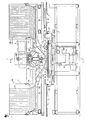
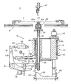
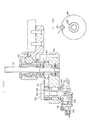
- FIG. 1 is a front view
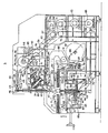
- FIG. 2 is a partially cutaway plan view
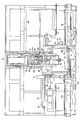
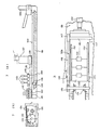
- FIG. 3 is a sectional view taken along the arrows A-A of FIG. 1
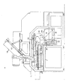
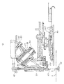
- FIG. 4 is a left-side view showing a portion in a sectional view
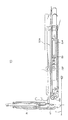
- FIG. 5 is a detail view of a clinch turret
- FIG. 6 is a schematic view showing the arrangement of taped electronic component feeders in a taped component holding and feeding device
- FIG. 7 shows a taped radial component feeder in which FIG. 7 (A) is a side view and FIG. 7 (B) is a plan view of the main portion
- FIG. 8 is a plan view of a taped axial component feeder
- FIG. 1 is a front view
- FIG. 2 is a partially cutaway plan view
- FIG. 3 is a sectional view taken along the arrows A-A of FIG. 1
- FIG. 4 is a left-side view showing a portion in a sectional view
- FIG. 5
- FIG. 9 is a side view of the taped radial component feeder
- FIG. 10 is a side view of the taped axial component feeder
- FIG. 11 shows an intermediate feeding device in which FIG. 11 (A) is a side view and FIG. 11 (B) is a detail view illustrating the shape of a cam plate.
- a printed-circuit board traverse device A (XY ⁇ table) on supports 2 fixed to a base frame 1, are secured a pair of guide rods 3 each having a circular section and extending in the right and left direction of FIG. 1 (the X direction).
- the XY ⁇ table is also provided with an X frame 5 having guide rod holders 4 which slide while holding the guide rods 3.
- the X frame 5 is reciprocated in the X direction along the guide rods 3 by a feed screw 7 to be turned by a motor 6 mounted on the base frame 1.
- a Y frame 9 which is guidedly moved in the Y direction is reciprocated by a feed screw 11 to be turned by a motor 10 attached to the X frame 5.
- grooved guide rollers 12 are rotatably journalled.
- the periphery of a round table 13 is fit into the grooves in the rollers 12 and is guidedly supported.
- a concentric gear 14 of a large diameter provided under the table 13 is meshed with a pinion 16 rotated by a motor 15 attached to the Y frame 9.
- the table 13 is rotated on its center axis ( ⁇ axis) from the reference position to the desired angle, e.g. 90°, 180° and 270°.
- Motors 6, 10 and 15 are numerically controlled according to a predetermined program.
- the motors 6 and 10 are DC servo motors and the motor 15 is a pulse motor.
- Printed-circuit board P is carried from a magazine (not shown) along a conveyor 17 provided on one side of the base frame 1 and having a guide rail.
- a push rod 19 fed by a feed drive chain 18 onto a printed-circuit board mounting frame 20 secured in the X direction on the round table 13 at the reference position, the printed-circuit board P is guidedly fed at the rightmost traversed position of the X frame 5 in FIG. 1.
- a pair of levers 22 are secured, and by fitting an engaging pin at each point of levers 22 into each of locating holes provided in the printed-circuit board P, the printed-circuit board P is located on the XY ⁇ table A.
- the engaging pin inserted in the locating hole is released by engaging the rod 21 with one of releasing means 23 at the right or left traversed ends of the X frame 5 and turning the rod.
- the printed-circuit board P on the XY ⁇ table A is taken out by a drawing hook 25 which is moved by a drawing driving chain 24 provided on the other side of the base frame 1, and then the board P is carried along a conveyor 26.
- the drawing hook 25 is fixed to the end of a long rod similar to the push rod 19 and is engaged with the edge of the printed-circuit board P on the side the board P is pushed in, at the leftmost traversed position of the X frame 5. Then, the drawing hook 25 draws out the board P.
- a turret support 27 is inclined forwardly at 45° and mounted on the base frame 1.
- a rotating shaft 28 is coaxially supported in the hollow portion of the turret support 27, a rotating shaft 28 is coaxially supported.
- the rotating shaft 28 is coupled to a pyramidal turret head 29 having a vertical angle of 90°, and the turret head 29 is axially supported outside the turret support 27 and concentric with it, with respect to the rotating shaft 28.
- a plurality of insertion spindles 31 (five in this embodiment) are mounted at equal spaces.
- spindles 31 correspond to the types of electronic components to be inserted into the inserting-holes in the printed-circuit board P.
- a locating pin 33 slides within a support pipe 32 fixed to the turret support 27 and fits into a locating hole provided in the turret head 29.
- the turret head 29 is located into a rotating position where one of the insertion spindles 31 is always perpendicular to the printed-circuit board P on the XY ⁇ table A. This location is engaged or disengaged by advancing or retracting the locating pin 33 by means of an air cylinder (not shown).
- the center line of the insertion spindle 31 located perpendicularly to the printed-circuit board is defined as a single fixed position O, and the movement range of the XY ⁇ table A is determined so that any portion of the entire surface of the printed-circuit board P on the table A can be moved to the single fixed position O.
- a bevel gear 34 To the rotating shaft 28 is fixed a bevel gear 34.
- the bevel gear 34 is engaged with a bevel gear 35.
- the rotating shaft of the bevel gear 35 is rotated by a motor 36 via a reduction gear 37, toothed pulleys 38 and 39, toothed belts 40 and 41 to index the insertion spindle selected under numerical control to the single fixed position O.
- the upper end of the insertion spindle 31 indexed to the single fixed position O is joined to a coaxial spindle operating rod 42.
- Cam followers 44a are in contact with rotating cams 45, and two levers 44 supported at a pivot shaft 43 on the base frame 1 are respectively rocked. This enables rings 46 engaged with the end of each of the levers 44 to couple the coaxial spindle operating rod 42 and depress it, thereby making an insertion head 47 perform a known lead inserting operation.
- a circular turret rest 51 is rotatably held by means of bearings 49 and 50 within a vertical support sleeve 48 fixed to the base frame 1, and to the lower portion of the circular turret rest 51, a toothed pulley 52 is fixed.
- the toothed pulley 52 is rotatively indexed by the motor 36 via the reduction gear 37, toothed pulleys 38, 53, 54 and 55 and toothed belts 56, 57, 58 and others in synchronism with the insertion spindle turret head 29.
- turret rest 51 On the turret rest 51, known clinch spindles 59 equal in number to the insertion spindles 31 on the insertion spindle column B are vertically mounted at equal spaces.
- the turret rest 51 is locked in position so that the axis of one of the clinch spindles 59 aligns to the single fixed position O.
- a locating pin 61 is guidedly held in a holding member 60, and when the pin 61 projects to engage with a locating hole in the turret rest 51, the turret rest 51 is locked in position.
- each clinch spindle 59 On the upper end of each clinch spindle 59 is provided a clinch head 62 for clinching the leads of the electronic component inserted by the insertion head 47.
- a roller 66 at the end of a lever 65 having a pivot shaft 64 is fit into a fork member 63 secured to the lower portion of the clinch spindle 59, and a cam follower 67 is attached to a lever 65a fixed to the pivot shaft 64.
- a cam 68 is in contact with the cam follower 67 and rocks the lever 65, thereby making the clinch head 62 perform the clinching operation.
- the cam 68 and the cams 45 for driving the insertion head 47 are synchronously rotated by a motor 69 via a clutch brake 70, a reduction gear 71, a toothed pulley 72, the transmission mechanism including toothed belts 73, 74 and 75, and a further toothed belt 76.
- a clutch brake 70 a reduction gear 71
- a toothed pulley 72 the transmission mechanism including toothed belts 73, 74 and 75
- a further toothed belt 76 a further toothed belt 76.
- FIG. 5 is a sectional view illustrating the details of the clinch turret C.
- the clinch spindle 59 for actuating the clinch head 62 is coaxially inserted in the hollow portion of an outer shaft 124.
- On the top of the outer shaft 124 is mounted the clinch head 62 for clinching the leads of the electronic component, and on the nose of the clinch spindle 59 is mounted an actuating piece 125 for opening and closing jaws 62a and 62a of the clinch head 62.
- This clinch head 62 is energized in the direction in which the jaws 62a and 62a are kept open.
- this clinch head 62 is designed so that the clinch spindle 59 is directly driven axially and that the outer shaft 124 rises integrally with the clinch spindle 59 through a compression spring (not shown) between the clinch spindle 59 and the outer shaft 124.
- the clinch spindle 59 rises together with the outer shaft 124, a stop ring 126 fixed to the lower end of the outer shaft 124 contacts the lower end of the cylindrical turret rest 51, and the rise of the outer shaft 124 is blocked.
- a fixed cam 127 is provided under the cylindrical turret rest 51.
- This fixed cam 127 is formed cylindrical and provided with a cam profile 128 on its upper edge.
- a cam follower 129 At the lower end of the clinch spindle 59 is mounted a cam follower 129 contacting the cam profile 128.
- This construction permits each clinch head 62 on the clinch spindle 59 to move axially, with the index rotation of the cylindrical turret rest 51; that is to say, the clinch head 62 moves axially so that at the single fixed position below the insertion head 47, the clinch head 62 can be placed in the upper position, while at the other positions, it can be placed in the lower position to such an extent that at least its nose does not interfere with the XY ⁇ table A.
- the clinch head 62 at the operating position is positioned in close vicinity to the printed-circuit board so as to minimize the up-and-down motion for the clinching operation, and the clinch heads 62 located except at the operating position are arranged so as not to interfere with the operations of the other relative devices.
- the lever 65 is engaged with the fork member 63 secured to the lower portion of the clinch spindle 59 at the single fixed position and is driven by the lever 65a through a connecting member 130 to move the clinch head 62 in the axial direction.
- the connecting member 130 is disengaged from the lever 65 by driving an actuator 131.
- the cam 68 can be deenergized by use of the actuator 131.
- 132 denotes an air cylinder for use as an auxiliary driving source.
- a piston rod 133 of this air cylinder 132 actuates to depress outwardly the end of the cam lever 65a on the side contacting the cam 68.
- the depressing operation makes the cam lever 65a turn counterclockwise, and the turning of the cam lever 65a makes the lever 65 raise the clinch head 62 at the single fixed position for making the clinch head 62 clinch the leads.
- the air cylinder 132 is actuated by a manual signal of a pushbutton switch or the like, and therefore, the rise of the clinch spindle 59 can be singly performed. Provision of this single-acting auxiliary driving source facilitates the correction of errors.
- the electronic component automatic insertion machine comes to a stop in response to a signal from an error detecting device (not shown), and the operator removes that incorrect component and inserts a replacement. Then by a manual signal of a switch, or the like, the air cylinder 132 is actuated to perform the clinching operation.
- the incorrect operation can be corrected instantaneously.
- auxiliary driving source is not limited to the air cylinder 132, but a known driving source such as a hydraulic cylinder or a solenoid can be applied widely.
- a taped component holding and feeding device D is provided behind the XY ⁇ table A.
- an upper guide rail 78 and a lower guide rail 79 (FIG. 2 shows only the left half of each rail) extending in parallel with each other in the right and left direction are fixedly supported on the upper and lower portions of a support 77 (FIG. 3) secured to the base frame 1.
- a lateral frame 80 holds the upper guide rail 78 slidably, and a guide roller 81 supported on the lateral frame 80 is adapted to come into contact with both sides of the lower dude rail 79.
- a numerically controlled servo motor 82 (FIG. 4) rotates a feed screw 84 via a toothed belt 83. As a result, the lateral frame 80 is guidedly moved in the right and left direction.
- a bent frame 88 which surrounds the fully rearward position of the Y frame 9 and extends forwards just above the printed-circuit board P on the XY ⁇ table A.
- an axial lead component feeder 90a (FIGS. 4 and 10) and a radial lead component feeder 90r (FIGS. 3 and 9) are placed in a line in the right and left direction for each reel 87 or carton 87a.
- the axial and radial lead component feeders 90a and 90r are respectively designed to hold the taped electronic component taken out of each reel 87 or carton 87a, with the leads of the electronic component cut off, and to feed it to the insertion head 47.
- the mounting plate 89 can be moved over the full right and left length in the base frame 1.
- the mounting plate 89 is controlled to move according to the predetermined program so that the feeder 90a or 90r for the selected electronic component can be located behind the single fixed position O.
- the axial lead component feeder 90a is constructed so that axial lead electronic components can be fed in their flat position, that is, with each electronic component lied flatly and the leads at both ends fixedly taped.
- the radial lead component feeder 90r is constructed so that radial lead electronic components can be fed in their vertical position, that is, with each electronic component standing and the lead down and fixedly taped. This eliminates the need for orientation when each of the axial lead electronic component or the radial lead electronic component is inserted into the inserting-holes in the printed-circuit board by means of the insertion head 47, and thus the inserting operation can be smoothly performed.
- the axial lead component feeder 90a becomes wide, which width is determined by a space between tapes for fastening both sides of the leads, but the radial lead component feeder 90r can be narrowed since the taped component itself is also moved in a vertical position.
- FIG. 6 there are provided two wide axial lead component feeders 90a and several narrow radial lead component feeders 90r, wherein the width ratio of each component feeder is selected so that the mounting pitch P1 of the wide axial lead component feeder 90a is an integer multiple, i.e. two times and three times, of the mounting pitch P2 of the narrow radial lead component feeder 90r.
- Each of the axial component feeder 90a and the radial component feeder 90r is designed so that the mounting pitch P1 or P2 can be positioned by locating pins 135 which are fit in pin holes 134. Accordingly, when from the circuit design conditions for the electronic components to be inserted into the printed-circuit board, it is required to insert various types of axial load electronic components and it becomes necessary to prepare another axial lead component feeder 90a in addition to the two shown feeders, the two left-hand radial lead electronic component feeders 90r are removed, the center locating pins 135 are removed from the pin holes 134, and then another axial lead component feeder 90a is mounted. In this way, the number of axial lead component feeders 90a can be soon increased.
- FIGS. 7 (A) and (B) are respectively a schematic side view of the radial lead component feeder 90r and a partially plan view of the end portion thereof.
- This radial lead component feeder 90r is formed as a removable device attached to the mounting plate 89 by means of a clamp 136 and is constructed as follows:
- An intermittent drive mechanism 137 comprising a known ratchet mechanism intermittently drives to rotate a toothed pulley 138. This operates, via a toothed belt 139, a shaft 141 of a toothed pulley 140, and a sprocket wheel 142 having feed pins attached to the shaft 141 rotates intermittently in the direction of the arrow.
- the feed pins of the sprocket wheel 142 are engaged with sprocket holes 145 in a tape 144 fastening radial lead electronic components 143 in the vertical position, and the radial lead electronic components 143 are intermittently fed in sequence to the end portion of the radial lead component feeder 90r. From the end portion, the components are transferred by a carrying arm means (intermediate feeding device 102; Fig. 11) to the insertion head 47.
- a carrying arm means intermediate feeding device 102; Fig. 11
- FIG. 8 is a schematic plan view of the axial component feeder 90a. Like the above radial lead component feeder 90r, this axial lead component feeder 90a is formed as a removable device attached to the mounting plate 89 by means of a clamp (not shown).
- the intermittent rotation of a toothed pulley 147 fixed to one end of a driving shaft 146 having an intermittent drive mechanism 137 (FIG. 8) comprising a ratchet mechanism is transmitted via a toothed belt 148 to a toothed pulley 149.
- a pair of right and left toothed wheels 151 are mounted on a shaft 150 of the toothed pulley 149 on the driven side.
- These wheels 151 are engaged with the leads of the axial lead electronic components 153 in the flat position attached to a pair of tapes 152 and 152 at a fixed pitch, and the axial lead electronic components 153 are intermittently fed in sequence to the end portion of the axial lead component feeder 90a. Then, a cylinder device 154 provided at the rear end of the axial lead component feeder 90a is actuated, whereby the topmost axial lead electronic component 153 advances together with the axial lead component feeder 90a and is carried to the single fixed position O just below the insertion head 47, and at that position, the leads are cut off, and the axial lead electronic component 153 is held in the insertion head 47. Also in this case, the locating pins 135 are securely inserted in the pin holes 134 in the mounting plate 89. As already mentioned, the locating pins 135 settle the lateral position of the mounting plate 89.
- FIG. 3 As a driving source of the axial lead and radial lead component feeders 90a and 90r for feeding taped components, in FIG. 3, there are provided rotating cams 91a and 91r coaxial with the cams 45, two levers 93 (only one is shown in FIG. 3) rocked around a pivot shaft 92 by both cams 91a and 91r, and the feed lever 94.
- the feed lever 94 is engaged with one of the two levers 93 selectively by means of an engaging and disengaging device by a control signal in accordance with whether the electronic component being selectively fed to the insertion head 47 is an axial lead component or a radial lead component, and the feed lever 94 is rocked.
- the feed lever 94 is engaged with none of the levers 93.
- the feed lever 94 is connected at its end to a tape feed drive shaft 95, and when the feed lever 94 is engaged with one of the two levers 93 as mentioned above, the lever 94 advances the shaft 95, which in turn advances one taped electronic component stopped just below.
- a rotating cam 96 (FIG. 2) coaxial with the cams 45.
- a cam follower 97a touches this cam 96 to rock a lever 97 having the pivot shaft 92.
- the lower portion of the lever 97 overlaps with the lever 94 and extends downwards, and its lower end is connected to one end of a hooked lever 99 (FIG. 2) which can be rotated about a fixed pin 98.
- the rocking of the lever 97 rotates the lever 99, the other end of the lever 99 makes a rack 100 slide perpendicularly to the sheet of FIG. 3 (refer to FIG. 11 (A)). This rotates a spline shaft 101.
- the spline shaft 101 supports an intermediate feeding device 102 (FIG. 11) for receiving a radial lead component from the radial lead feeder 90r and supplying it to the insertion head 47.
- the spline shaft 101 moves up and down by an air cylinder (not shown).
- the lower portion of this shaft 101 is provided with a toothed pulley 103, and the shaft 101 is rotatably mounted on a frame 104 which is prevented from rotating with respect to the base frame 1.
- the frame 104 is provided with a cam shaft 105 belt-driven from the toothed pulley 103 and a concentric intermediate shaft 106 inside the cam shaft 105.
- the cam shaft 105 is provided with a unitary cam plate 107 shown in FIG. 11 (B).
- the intermediate shaft 106 supports a chucking member 108 which is guidedly slidable perpendicularly to the shaft 106.
- the chucking member 108 is attracted by a spring 109 towards the intermediate shaft 106.
- a roller 110 journalled on the chucking member 108 is normally fit into a recess 111 provided in the cam plate 107.
- the cam shaft 105 rotates the intermediate shaft 106 and they rotate together.
- the cam shaft 105 rotates to the position in which the chucking member 108 is opposite to the radial lead component feeder 90r or the insertion head 47
- the intermediate shaft 106 is stopped rotating as a stop member 112 hits a stop (not shown).
- the cam shaft 105 further rotates about 20°, the roller 110 is pushed out of the recess 111 and advances the chucking member 108.
- the electronic component is given, as mentioned above.
- the intermediate feeding device 102 When an axial lead component is being inserted, the intermediate feeding device 102 is retracted to the upper position shown in a solid line of FIG. 3 so as not to prevent the advancement of the axial lead component feeder 90a. However, when a radial lead component is being inserted, the intermediate feeding device 102 lowers to the position shown in a dot and dash line of FIG. 3, the chucking member 108 rotates 180° and receives the radial lead component from the radial lead component feeder 90r, and then, the chucking member 108 reverses 180° and feeds the radial lead component to the insertion head 47. After that, the intermediate feeding device 102 rises.
- the spline shaft 101 rises and falls according to a program for selectively feeding radial lead components, and the timing of the rotation of the spline shaft 101 and the timing of the operation of the chucking member 108 are governed by the cam 96.
- An air cylinder 113 (FIG. 3) turns a jig 115 pivoted to the base frame 1 by a pin 114 and depresses the lever 44, thereby compensating for cutting and bending forces against the leads of the axial lead component.
- 116 is a rotaty encoder which rotates in synchronism with the rotation of the cams 45 and generates necessary control signals.
- stick holding racks 118 in which many columns of sticks 117 in the right and left direction are closely arranged.
- the sticks 117 arrange and hold DIP ICs classified by the type.
- Each holding rack 118 is also capable of holding plural rows of sticks in the vertical direction. From the lower end of each stick 117 (when plural rows of sticks are accommodated in the vertical direction, from the stick at the lowest portion), ICs are selectively carried, changed their attitudes through a guide tube 119 and supplied onto a belt conveyor 120.
- the ICs on the conveyor 120, while descending a chute, are properly oriented by means of a known additional function device 122, stop at the standby position of the chute outlet, and then, supplied to the insertion head 47.
- the aforementioned XY ⁇ table A, taped component holding and feeding device D, and stick component holding and feeding devices E are wholly controlled by an NC unit provided within the base frame 1.
- the NC unit comprises two sections: a fixed sequence control section for carrying the printed-circuit board onto the XY ⁇ table A, positioning the board in the table A and carrying the board out of the table A; and a variable program control section for selecting the holding and feeding device D or E to be used, selecting the insertion spindle and clinch spindle according to the type of an electronic component to be inserted, moving the printed circuit board P with respect to the selected electronic component, to the single fixed position P.
- the printed-circuit board P is fed from the conveyor 17 onto the XY ⁇ table A, and locked in position.
- Electronic components to be inserted from the holding and feeding device D or E to the printed-circuit board P are taken out one by one in accordance with the predetermined sequence
- the spindle column B and the clinch turret C are rotatively indexed by the motor 36 so that the insertion spindle 31 and the clinch spindle 59 are located in the single fixed position O, and the electronic components taken out are supplied to the insertion head 47.
- the XY ⁇ table A traverses the printed-circuit board P to the position in which the electronic component insertion portion aligns to the single fixed position O. Then the rotations of cams 45 and 68 permit the insertion head 47 and the clinch head 62 to cooperate with each other, thereby inserting the above electronic component.
- the rotating cams 45 and 68 are stopped rotating by the clutch brake 70.
- the releasing means 23 depresses a release lever 23a fixed to the rod 21 at the traversed end of the XY ⁇ table A to release the locating pin of the printed-circuit board P.
- the printed-circuit board P is taken out by the drawing hook 25 and carried out along the conveyor 26.
- cams 45 and 68 are mechanically synchronized to rotate, it is easy to synchronize them electrically to rotate.
- the present invention is of the aforementioned construction and has the following marked effects: (1) Since the insertion spindle and the clinch spindle perform the inserting operation of a predetermined electronic component fed from the feeding device, in a position of the printed-circuit board which has reached to the single fixed position opposed to the above spindles, a variety of electronic components can be inserted while the printed-circuit board is traversed sequentially from its end, and the traverse amount of the printed-circuit board is minimized as much as possible, thereby increasing the efficiency of the inserting operation and minimizing the size of the printed-circuit board traverse device.
Landscapes
- Engineering & Computer Science (AREA)
- Manufacturing & Machinery (AREA)
- Microelectronics & Electronic Packaging (AREA)
- Supply And Installment Of Electrical Components (AREA)
Claims (9)
- Automatische Einsetzmaschine für elektronische Bauelemente mit einer Leiterplatten-Verschiebevorrichtung (A) zum Tragen einer Leiterplatte (P) und zum Verschieben derselben derart, daß ein in der Leiterplatte vorhandenes Aufnahmeloch für eine Zuleitung für ein elektronisches Bauelement eingesetzt werden soll, an eine einzige ortsfeste Stelle gelangt, und mit einer oberhalb der Verschiebevorrichtung (A) angeordnete Einsetzspindelsäule (B) zum Fortschalten einer Mehrzahl von Einsetzspindeln (31) an die einzige feste ortsfeste Stelle (O), wobei die Einsetzspindeln (31) den Arten der in die Aufnahmelöcher der Leiterplatte (P) einzusetzenden elektronischen Bauelemente entsprechen, dadurch gekennzeichnet, daß die Einsetzspindeln (1) sich voneinander unterscheiden und daß jede Einsetzspindeln (31) in Abhängigkeit von dem gewählten, in ein an der einzigen ortsfesten Stelle (O) befindliches Aufnahmeloch einzusetzenden Bauelementes wahlweise fortgeschaltet wird.
- Automatische Einsetzmaschine nach Anspruch 1, dadurch gekennzeichnet, daß die Einsetzspindeln (31) durch Drehen im Uhrzeigersinn oder im Gegenuhrzeigersinn fortgeschaltet werden und daß eine der Einsetzspindeln (31) ausgewählt und an die einzige ortsfeste Stelle gedreht wird.
- Automatische Einsetzmaschine nach Anspruch 1 oder 2, dadurch gekennzeichnet, daß eine Vorrichtung (D) zum Halten und Verschieben von gegurteten Bauelementen vorgesehen ist, die eine Mehrzahl von Zubringern (90a, 90 r) für gegurtete elektronische Bauelemente besitzt, wobei diese Zubringer zum Halten von Bauelementen mit axialer Zuleitung bzw. mit radialer Zuleitung und zum Zuführen der genannten Bauelemente nacheinander zu den Einsetzspindeln (31) eingerichtet sind, einer der Zubringer (90a, 90r) für gegurtete Bauelemente beliebig ausgewählt und bis in die Nähe der einzigen ortsfesten Stelle (O) fortgeschaltet wird, die Vorrichtung (D) zum Halten und Zuführen von gegurteten Bauelementen dazu eingerichtet ist, das jeweils ausgewählte elektronische Bauelement der an die einzige ortsfeste Stelle (O) fortgeschalteten Einsetzspindel (31) zuzuführen; und/oder eine Vorrichtung (E) zum Halten und Zuführen von stabförmig gepackten Bauelementen vorgesehen ist, die dazu dient, einem die elektronischen Bauelemente der Stäbe haltenden Stabhaltegestell (118) ein ausgewähltes elektronisches Bauelement zu entnehmen und herauszutragen und der an die einzige ortsfeste Stelle (O) fortgeschalteten Einsetzspindel (31) zuzuführen.
- Automatische Einsetzmaschine nach Anspruch 3, dadurch gekennzeichnet, daß die Vorrichtung (E) zum Halten und Zuführen von stabförmig gepackten Bauelementen auf der rechten und der linken Seite der Einsetzspindelsäule (B) angeordnet ist.
- Automatische Einsetzmaschine nach Anspruch 3, dadurch gekennzeichnet, daß die Vorrichtung (D) zum Halten und Zuführen von gegurteten Bauelementen eine Mehrzahl von Zubringern (90a, 590r) für gegurtete Bauelemente besitzt, wobei diese Zubringer an einer Stelle unterhalb und hinter der Einsetzspindelsäule (B) auf einer Tragplatte (89) angeordnet sind, die gegenüber der Einsetzspindelsäule (B) nach links und rechts bewegbar ist, und jeder der Zubringer (90a, 90r) für gegurtete elektronische Bauelemente zum Halten zahlreicher gegurteter elektronischer Bauelemente geeignet ist, die beliebig ausgewählt und an eine der einzigen ortsfesten Stelle (O) entsprechende, ortsfeste Stelle fortgeschaltet werden, so daß die Vorrichtung (D) zum Halten und Zuführen von gegurteten Bauelementen die elektronischen Bauelement der fortgeschalteten Einsetzspindel (31) zuführt.
- Automatische Einsetzmaschine nach Anspruch 5, dadurch gekennzeichnet, daß die Zubringer (90a, 90r) für gegurtete elektronische Bauelemente einen Zubringer (90a) für Bauelemente mit axialer Zuleitung besitzen, der zum Zuführen von Bauelementen mit axialer Zuleitung dient, und einen Zubringer (90r) für Bauelemente mit radialer Zuleitung, der zum Zuführen von Bauelementen mit radialer Zuleitung dient, daß eine Mehrzahl der Zubringer (90a, 90r) für Bauelemente mit axialer bzw. mit radialer Zuleitung an Stellen montiert sind, die durch Positionierstifte (135) auf der Tragplatte (89) vorherbestimmt sind, wobei die Aufnahmebreite für den Zubringer (90a) für Bauelemente mit axialer Zuleitung ein ganzzahliges Vielfaches der Aufnahmebreite für den Zubringer (90r) für Bauelemente mit radialer Zuleitung ist.
- Automatische Einsetzmaschine nach Anspruch 6, dadurch gekennzeichnet, daß die Positionierstifte (135) in der Tragplatte (89) herausnehmbar sind.
- Automatische Einsetzmaschine nach eine der vorhergehenden Ansprüche 3 bis 7, dadurch gekennzeichnet, daß die Vorrichtung (D) zum Halten und Zuführen von gegurteten Bauelementen eine in der Querrichtung gegenüber der Einsetzspindelsäule (B) nach links und rechts bewegbare Tragplatte (89) besitzt, die an einer ortsfesten Stelle angeordnet ist, die der einzigen ortsfesten Stelle (O) entspricht, ferner einen Zubringer (90r) für Bauelemente mit radialer Zuleitung, wobei diese Zubringer auf der Tragplatte (89) angeordnet sind, ferner nur eine Antriebsquelle (91a, 91r, 92 - 94), die an einer ortsfesten Stelle oberhalb der Tragplatte (89) angeordnet ist und durch die Querbewegung der Tragplatte (89) zum Angriff an einer Antriebswelle (95) eines intermittieren Schaltwerks (137) für den Zubringer (90a) für Bauelemente mit axialer Zuleitung bringbar ist, wenn sich derartiger Zubringer an einer vorherbestimmten Stelle in der Nähe der einzigen ortsfesten Stelle (O) befindet.
- Automatische Einsetzmaschine nach einem der vorhergehenden Ansprüche mit einem unter der Leiterplatten-Verschiebevorrichtung (A) angeordneten Clinchrevolverkopf (C), der zum Halten einer Mehrzahl von Clinchspindeln (59) dient, die mit den Einsatzspindeln (31) zusammenwirken und an die einzige ortsfeste Stelle drehfortschaltbar sind, wobei jede Clinchspindel einer an die einzige ortsfeste Stelle drehfortgeschalteten Einsetzspindel (31) entspricht.
Applications Claiming Priority (6)
| Application Number | Priority Date | Filing Date | Title |
|---|---|---|---|
| JP59189744A JPS6167985A (ja) | 1984-09-12 | 1984-09-12 | 電子部品自動插入機 |
| JP13720684U JPH0310709Y2 (de) | 1984-09-12 | 1984-09-12 | |
| JP137206/84U | 1984-09-12 | ||
| JP189744/84 | 1984-09-12 | ||
| JP139012/84U | 1984-09-13 | ||
| JP13901284U JPH0319280Y2 (de) | 1984-09-13 | 1984-09-13 |
Publications (3)
| Publication Number | Publication Date |
|---|---|
| EP0195086A1 EP0195086A1 (de) | 1986-09-24 |
| EP0195086A4 EP0195086A4 (de) | 1989-03-29 |
| EP0195086B1 true EP0195086B1 (de) | 1992-08-12 |
Family
ID=27317428
Family Applications (1)
| Application Number | Title | Priority Date | Filing Date |
|---|---|---|---|
| EP85904495A Expired - Lifetime EP0195086B1 (de) | 1984-09-12 | 1985-09-09 | Vorrichtung zum automatischen einführen von elektronischen bauteilen |
Country Status (7)
| Country | Link |
|---|---|
| US (1) | US4745679A (de) |
| EP (1) | EP0195086B1 (de) |
| KR (1) | KR920003402B1 (de) |
| DE (1) | DE3586495T2 (de) |
| HK (1) | HK28893A (de) |
| SG (1) | SG693G (de) |
| WO (1) | WO1986001971A1 (de) |
Families Citing this family (11)
| Publication number | Priority date | Publication date | Assignee | Title |
|---|---|---|---|---|
| DE3737506A1 (de) * | 1987-11-05 | 1989-05-24 | Ibm Deutschland | Vorrichtung zur bestueckung insbesondere von leiterplatten |
| US5165165A (en) * | 1989-06-02 | 1992-11-24 | Canon Kabushiki Kaisha | Part inserting apparatus and method for use |
| US5210933A (en) * | 1990-10-30 | 1993-05-18 | Komatsu Giken Co., Ltd. | Circuit assembly robot |
| USD342748S (en) | 1990-11-02 | 1993-12-28 | Mydata Automation Ab | Component mounting machine |
| USD342533S (en) | 1990-11-02 | 1993-12-21 | Mydata Automation Ab | Component mounting machine |
| JP3340579B2 (ja) * | 1995-02-22 | 2002-11-05 | 松下電器産業株式会社 | 電子部品実装装置 |
| USRE40283E1 (en) | 1995-02-22 | 2008-05-06 | Matsushita Electric Industrial Co., Ltd. | Mounting apparatus for electronic component |
| JPH10313195A (ja) * | 1997-05-12 | 1998-11-24 | Fuji Mach Mfg Co Ltd | 回転型回路部品供給装置および回路部品供給方法 |
| US6139079A (en) * | 1997-10-20 | 2000-10-31 | Motorola, Inc. | Universal transport apparatus |
| US9769970B2 (en) * | 2015-12-16 | 2017-09-19 | Panasonic Factory Solutions Asia Pacific | Apparatus and method for feeding electronic components for insertion onto circuit boards |
| JP7373765B2 (ja) * | 2019-06-03 | 2023-11-06 | パナソニックIpマネジメント株式会社 | 部品実装装置およびそれを用いた部品実装基板の製造方法 |
Citations (1)
| Publication number | Priority date | Publication date | Assignee | Title |
|---|---|---|---|---|
| EP0155512A2 (de) * | 1984-02-17 | 1985-09-25 | Matsushita Electric Industrial Co., Ltd. | Vorrichtung zur automatischen Montage elektronischer Bauteile |
Family Cites Families (3)
| Publication number | Priority date | Publication date | Assignee | Title |
|---|---|---|---|---|
| JPS5335957A (en) * | 1976-09-16 | 1978-04-03 | Tdk Electronics Co Ltd | Device for accommodating and feeding series of electronic parts |
| US4063347A (en) * | 1976-10-01 | 1977-12-20 | Usm Corporation | Machine for inserting multi-lead components sequentially |
| JPS54126962A (en) * | 1978-03-24 | 1979-10-02 | Fuji Machine Mfg | Method of and apparatus for inserting electronic components into printed board |
-
1985
- 1985-09-09 DE DE8585904495T patent/DE3586495T2/de not_active Expired - Fee Related
- 1985-09-09 WO PCT/JP1985/000504 patent/WO1986001971A1/ja not_active Ceased
- 1985-09-09 US US06/858,443 patent/US4745679A/en not_active Expired - Lifetime
- 1985-09-09 EP EP85904495A patent/EP0195086B1/de not_active Expired - Lifetime
- 1985-09-09 KR KR1019860700253A patent/KR920003402B1/ko not_active Expired
-
1993
- 1993-01-04 SG SG6/93A patent/SG693G/en unknown
- 1993-03-25 HK HK288/93A patent/HK28893A/en not_active IP Right Cessation
Patent Citations (1)
| Publication number | Priority date | Publication date | Assignee | Title |
|---|---|---|---|---|
| EP0155512A2 (de) * | 1984-02-17 | 1985-09-25 | Matsushita Electric Industrial Co., Ltd. | Vorrichtung zur automatischen Montage elektronischer Bauteile |
Also Published As
| Publication number | Publication date |
|---|---|
| EP0195086A4 (de) | 1989-03-29 |
| SG693G (en) | 1993-03-12 |
| EP0195086A1 (de) | 1986-09-24 |
| US4745679A (en) | 1988-05-24 |
| HK28893A (en) | 1993-04-02 |
| WO1986001971A1 (fr) | 1986-03-27 |
| DE3586495T2 (de) | 1993-02-25 |
| DE3586495D1 (de) | 1992-09-17 |
| KR860700337A (ko) | 1986-08-01 |
| KR920003402B1 (ko) | 1992-04-30 |
Similar Documents
| Publication | Publication Date | Title |
|---|---|---|
| US4054988A (en) | Machine for processing and securing parallel lead electronic circuit elements to a printed circuit board | |
| EP0195086B1 (de) | Vorrichtung zum automatischen einführen von elektronischen bauteilen | |
| US4329776A (en) | Component inserting apparatus | |
| US4293999A (en) | Radial lead inserting machine | |
| HRP960016A2 (en) | Machine tool | |
| JPH11135985A (ja) | 電気部品供給方法および装置ならびに電気部品装着装置 | |
| US4197637A (en) | Automated assembly apparatus for printed circuit boards | |
| KR100320011B1 (ko) | 파이프,로드및섹션부재와같은와이어류재료굽힘장치 | |
| US4774759A (en) | Part inserting apparatus | |
| US4670977A (en) | Inserter device for electronic components | |
| US4539740A (en) | Inserter device for electronic components | |
| US4370804A (en) | Electronic component inserting apparatus | |
| US4631981A (en) | Machine tool with two tool changers | |
| EP0154652B1 (de) | Aufbauvorrichtung für elektronische teile | |
| GB1358424A (en) | Multiple spindle automatic lathe | |
| US4068373A (en) | Component insertion machine | |
| US3859707A (en) | Electronic component semi-automatic assembly machine | |
| JPS6167985A (ja) | 電子部品自動插入機 | |
| JPS61105900A (ja) | 電子部品自動插入機 | |
| JPH025038B2 (de) | ||
| US3254821A (en) | Automatic transistor insertion machine | |
| CN220427662U (zh) | 一种便于送料的装置 | |
| JPH07308826A (ja) | 部品装着方法 | |
| JPS5822636A (ja) | 工具交換装置 | |
| JPH05198970A (ja) | 電子部品自動段取装置 |
Legal Events
| Date | Code | Title | Description |
|---|---|---|---|
| PUAI | Public reference made under article 153(3) epc to a published international application that has entered the european phase |
Free format text: ORIGINAL CODE: 0009012 |
|
| AK | Designated contracting states |
Kind code of ref document: A1 Designated state(s): DE FR GB |
|
| 17P | Request for examination filed |
Effective date: 19860915 |
|
| A4 | Supplementary search report drawn up and despatched |
Effective date: 19890329 |
|
| 17Q | First examination report despatched |
Effective date: 19901001 |
|
| GRAA | (expected) grant |
Free format text: ORIGINAL CODE: 0009210 |
|
| AK | Designated contracting states |
Kind code of ref document: B1 Designated state(s): DE FR GB |
|
| REF | Corresponds to: |
Ref document number: 3586495 Country of ref document: DE Date of ref document: 19920917 |
|
| ET | Fr: translation filed | ||
| PLBE | No opposition filed within time limit |
Free format text: ORIGINAL CODE: 0009261 |
|
| STAA | Information on the status of an ep patent application or granted ep patent |
Free format text: STATUS: NO OPPOSITION FILED WITHIN TIME LIMIT |
|
| 26N | No opposition filed | ||
| PGFP | Annual fee paid to national office [announced via postgrant information from national office to epo] |
Ref country code: FR Payment date: 20010911 Year of fee payment: 17 |
|
| PGFP | Annual fee paid to national office [announced via postgrant information from national office to epo] |
Ref country code: GB Payment date: 20010912 Year of fee payment: 17 |
|
| PGFP | Annual fee paid to national office [announced via postgrant information from national office to epo] |
Ref country code: DE Payment date: 20010924 Year of fee payment: 17 |
|
| REG | Reference to a national code |
Ref country code: GB Ref legal event code: IF02 |
|
| PG25 | Lapsed in a contracting state [announced via postgrant information from national office to epo] |
Ref country code: GB Free format text: LAPSE BECAUSE OF NON-PAYMENT OF DUE FEES Effective date: 20020909 |
|
| PG25 | Lapsed in a contracting state [announced via postgrant information from national office to epo] |
Ref country code: DE Free format text: LAPSE BECAUSE OF NON-PAYMENT OF DUE FEES Effective date: 20030401 |
|
| GBPC | Gb: european patent ceased through non-payment of renewal fee |
Effective date: 20020909 |
|
| PG25 | Lapsed in a contracting state [announced via postgrant information from national office to epo] |
Ref country code: FR Free format text: LAPSE BECAUSE OF NON-PAYMENT OF DUE FEES Effective date: 20030603 |
|
| REG | Reference to a national code |
Ref country code: FR Ref legal event code: ST |