EP0194234A1 - Einrichtung zum Automatisieren von operativen Systemen mit mechanischer Hand oder dergleichen - Google Patents
Einrichtung zum Automatisieren von operativen Systemen mit mechanischer Hand oder dergleichen Download PDFInfo
- Publication number
- EP0194234A1 EP0194234A1 EP86830026A EP86830026A EP0194234A1 EP 0194234 A1 EP0194234 A1 EP 0194234A1 EP 86830026 A EP86830026 A EP 86830026A EP 86830026 A EP86830026 A EP 86830026A EP 0194234 A1 EP0194234 A1 EP 0194234A1
- Authority
- EP
- European Patent Office
- Prior art keywords
- sensor
- tool
- piston
- stem
- mechanical hand
- Prior art date
- Legal status (The legal status is an assumption and is not a legal conclusion. Google has not performed a legal analysis and makes no representation as to the accuracy of the status listed.)
- Granted
Links
Images


Classifications
-
- B—PERFORMING OPERATIONS; TRANSPORTING
- B25—HAND TOOLS; PORTABLE POWER-DRIVEN TOOLS; MANIPULATORS
- B25J—MANIPULATORS; CHAMBERS PROVIDED WITH MANIPULATION DEVICES
- B25J19/00—Accessories fitted to manipulators, e.g. for monitoring, for viewing; Safety devices combined with or specially adapted for use in connection with manipulators
- B25J19/02—Sensing devices
- B25J19/021—Optical sensing devices
-
- B—PERFORMING OPERATIONS; TRANSPORTING
- B25—HAND TOOLS; PORTABLE POWER-DRIVEN TOOLS; MANIPULATORS
- B25J—MANIPULATORS; CHAMBERS PROVIDED WITH MANIPULATION DEVICES
- B25J13/00—Controls for manipulators
- B25J13/08—Controls for manipulators by means of sensing devices, e.g. viewing or touching devices
- B25J13/081—Touching devices, e.g. pressure-sensitive
- B25J13/082—Grasping-force detectors
-
- B—PERFORMING OPERATIONS; TRANSPORTING
- B25—HAND TOOLS; PORTABLE POWER-DRIVEN TOOLS; MANIPULATORS
- B25J—MANIPULATORS; CHAMBERS PROVIDED WITH MANIPULATION DEVICES
- B25J15/00—Gripping heads and other end effectors
- B25J15/02—Gripping heads and other end effectors servo-actuated
- B25J15/0253—Gripping heads and other end effectors servo-actuated comprising parallel grippers
- B25J15/026—Gripping heads and other end effectors servo-actuated comprising parallel grippers actuated by gears
-
- B—PERFORMING OPERATIONS; TRANSPORTING
- B25—HAND TOOLS; PORTABLE POWER-DRIVEN TOOLS; MANIPULATORS
- B25J—MANIPULATORS; CHAMBERS PROVIDED WITH MANIPULATION DEVICES
- B25J15/00—Gripping heads and other end effectors
- B25J15/04—Gripping heads and other end effectors with provision for the remote detachment or exchange of the head or parts thereof
-
- Y—GENERAL TAGGING OF NEW TECHNOLOGICAL DEVELOPMENTS; GENERAL TAGGING OF CROSS-SECTIONAL TECHNOLOGIES SPANNING OVER SEVERAL SECTIONS OF THE IPC; TECHNICAL SUBJECTS COVERED BY FORMER USPC CROSS-REFERENCE ART COLLECTIONS [XRACs] AND DIGESTS
- Y10—TECHNICAL SUBJECTS COVERED BY FORMER USPC
- Y10S—TECHNICAL SUBJECTS COVERED BY FORMER USPC CROSS-REFERENCE ART COLLECTIONS [XRACs] AND DIGESTS
- Y10S279/00—Chucks or sockets
- Y10S279/904—Quick change socket
- Y10S279/905—Quick change socket with ball detent
-
- Y—GENERAL TAGGING OF NEW TECHNOLOGICAL DEVELOPMENTS; GENERAL TAGGING OF CROSS-SECTIONAL TECHNOLOGIES SPANNING OVER SEVERAL SECTIONS OF THE IPC; TECHNICAL SUBJECTS COVERED BY FORMER USPC CROSS-REFERENCE ART COLLECTIONS [XRACs] AND DIGESTS
- Y10—TECHNICAL SUBJECTS COVERED BY FORMER USPC
- Y10T—TECHNICAL SUBJECTS COVERED BY FORMER US CLASSIFICATION
- Y10T279/00—Chucks or sockets
- Y10T279/17—Socket type
- Y10T279/17666—Radially reciprocating jaws
- Y10T279/17692—Moving-cam actuator
- Y10T279/17743—Reciprocating cam sleeve
- Y10T279/17752—Ball or roller jaws
-
- Y—GENERAL TAGGING OF NEW TECHNOLOGICAL DEVELOPMENTS; GENERAL TAGGING OF CROSS-SECTIONAL TECHNOLOGIES SPANNING OVER SEVERAL SECTIONS OF THE IPC; TECHNICAL SUBJECTS COVERED BY FORMER USPC CROSS-REFERENCE ART COLLECTIONS [XRACs] AND DIGESTS
- Y10—TECHNICAL SUBJECTS COVERED BY FORMER USPC
- Y10T—TECHNICAL SUBJECTS COVERED BY FORMER US CLASSIFICATION
- Y10T29/00—Metal working
- Y10T29/53—Means to assemble or disassemble
- Y10T29/53039—Means to assemble or disassemble with control means energized in response to activator stimulated by condition sensor
-
- Y—GENERAL TAGGING OF NEW TECHNOLOGICAL DEVELOPMENTS; GENERAL TAGGING OF CROSS-SECTIONAL TECHNOLOGIES SPANNING OVER SEVERAL SECTIONS OF THE IPC; TECHNICAL SUBJECTS COVERED BY FORMER USPC CROSS-REFERENCE ART COLLECTIONS [XRACs] AND DIGESTS
- Y10—TECHNICAL SUBJECTS COVERED BY FORMER USPC
- Y10T—TECHNICAL SUBJECTS COVERED BY FORMER US CLASSIFICATION
- Y10T29/00—Metal working
- Y10T29/53—Means to assemble or disassemble
- Y10T29/53087—Means to assemble or disassemble with signal, scale, illuminator, or optical viewer
Definitions
- the invention relates to an apparatus for handling and assembling electronic components and for other equivalent uses, comprising a mobile hand to which a device with a mobile operative tool can be applied to carry out the operation, a power system being provided to drive the operative toot.
- the apparatus comprises a sensor device concordantly acting with the power system but with limited power, which is associated with a sight to determine a consensus to the actuation of the operation respectively to the activation of the power system when -in the absence of irregularities for lack, or selection, or positioning of the component to be applied -said sensor device cooperates with the sight in a programmed way.
- the sensor device can be predisposed to impose an initial displacement of operative members cooperating with a component to be handled.
- the sensor device may comprise a sensor stem acting concordantly with and on the same manoeuvring member of the mechanical hand, upon which the operative system acts as well; said sensor stem being operated by a weak-power drive means.
- the sight associated with the sensor device may be an optical sight, or a photoelectric, or magnetic, or electrical or mechanical or other type sight
- the weak-power drive means can act on a lever which pushes the sensor stem and intercepts the sight upon the actuation of an initial displacement of the manoeuvring mobile member.
- Said sensor stem may be slidingly housed in the stem -in this case being made tubular -of the piston of the power system.
- the apparatus may comprise a pressure sensor interposed between the power system and said manoeuvring member in order to limit the actuation forces.
- the apparatus may also comprise a sensor for controlling the presence of the mechanical hand.
- the invention may be applied to an improved fixture for blocking a toot on the arm of a robot or for other uses, including a body with a cavity for the shank of a tool provided with a groove, and groove engaging pegs housed into seats radially disposed in respect to said cavity.
- the fixture may also comprise a cylinder-annular piston system surrounding said body and able to act through inclined surfaces upon balls forming said engaging pegs.
- the groove of the tool shank may have an inclined surface upon which the balls act, thereby imposing an axial thrust component which forces the toot against a surface of the fixture body.
- Passages provided within the body and the tool may be put into communication to each other upon the axial forced coupling between the body and the tool.
- the piston of annular cross section has a coaxial inner cone surface which acts upon the balls.
- Said piston is able to cooperate with a limit stop, when a shank to be blocked is not present, thus avoiding an action on the balls and the retaining means of the same balls.
- the blocking fixture may comprise sensors for the control and consensus of the piston, of the locking and release of the shank, of the tool presence and of the resistence exibited by an axial stem.
- a sensor is provided cooperating with an appendix of the annular piston for the locking and release of the tool shank.
- a proximity sensor may also be provided for evaluating the position of the fever connected to the axial sensor stem inside the power piston.
- the fixture may also comprise a proximity sensor, being at the level of the contact surface with the tool body.
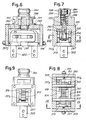
- numeral 128 indicates a head connected to the manoeuvre arm of a manipulator or "robot"; said head is predisposed to receive a replaceable tool, representing a mobile hand or mechanical hand, generally indicated by 140.
- the head 128 comprises a main block 14 and a fitting block 144 assembled between them-
- the fitting block 144 has a seat 146 for engagement on the end of the robot arm to which said block may be tightened by means, for example, of the tangential screw 14 8.
- the block 1 4 4 has a diametral slot 150 within which a lever element 152 can move, pivoted at 154 and provided with an adjustable stop member 156.
- the fitting block 144 forms lugs 158 on which the terminals 1 60, 162 of an optical sight can be mounted, said sight -of photoelectric, reflection, or magnetic, or electrical, or mechanical or other type -being apt to cooperate with the mobile end of the lever element 152 to determine a consensus to be later described in more detail.
- the cylindrical seat for a small piston 164 - hydraulic or pneumatic - is formed, this piston being able to act on the lever element 152 against a weak counteracting spring 166.
- the lever 152 cooperates with the upper end plate of a sensor stem 168 extending inside the main block 142 which is made up of two parts 142A and 142B.
- the main part 142A of the main block 142 makes up the cylindrical cavity 170 of a double-acting power piston 172 driven through two side connections, one of which is indicated by 174 in the drawing.
- the stem 176 of the power piston 172 is tubular and slidingly houses the sensor stem 168.
- a sensor is advantageously provided capable of sensing the presence or the absence of the mechanical hand 140 which is to be fitted into the seat 180.
- a through seat 288 is predisposed longitudinally crossed by a manoeuvre column 290 which drives the operative members of the mechanical hand 140 described herebelow.
- the upper end of column 290 is housed in an axial end dead hole 168A of the sensor stem 168.
- This column 290 is at least partially threaded for engaging an adjustable pawl 296 practically made up of a nut and a lock nut
- a spring 298, reacting on the body of the mobile or mechanical hand 140 acts from down upwards while, on the adjustable pawl 296 -after an adjustable run - both the lower end of the sensor stem 168 and the lower end of the stem 176 of the power piston 172 can act from up downwards.
- the assembly 290, 296 makes up the manoeuvre member of the mechanical hand.
- the shank 284 of the body 286 of the mechanical hand 140 is fitted into the fitting seat 180 of the main block 142 of the head 128.
- a box housing 291 is engaged being provided with end plates 292 which are, in turn, provided with screw registers 294 intended to limit the opening of the clamp jaws.
- the housing 291 with plates 292 defines a sliding seat 295 into which two similar slide members 297 can slide, each of them forming one of the jaws 300.
- slide members are slidingly guided with their walls 297A against the inner sides of the box housing 291; for the straight line guide of the two slide members 297, according to the double arrows f297, two pivots 302 are provided which go through the sliding seat 295 and slots 304 formed in the walls 297A of the slide members 297. In the walls 297A, respective open slots 306 are also formed, perpendicular to slots 304.
- each sector 308 is idly mounted each one having a peg 310 apt to be housed in the respective open slot 306.
- respective toothed wheels 3 1 2 are also idly mounted, which are coupled to the respective sectors 308 through diametral keys 3 1 4 and relevant keyways.
- the two toothed wheels 312 mesh with respective straight-line rack toothings of a rack member 316.
- This rack member 316 is axially drilled with a passage having two diameters, constituting an abutment for the end head 318 of the column 290.
- This column 290 has a shoulder 320 formed as an open elastic ring on which a spring 322 rests, which spring reacts on the rack member 316 so as to urge this member in abutment against the head 318.
- the column 290 In order to cause the closure of the clamp, that is, the mutual approach of jaws 300, the column 290 must be lowered by a compression of spring 298. Accordingly, through the shoulder 320 and the spring 322, the rack member 316 is also lowered. This member 316 goes down until resistances to the lowering greater than the thrust exerted through the spring 322 are encountered, after that the rack member 316 stops and only the lowering of the column 290 continues with the head 318 moving away from the abutment made up of the two-diameters hole inside the member 316.
- the two toothed wheels 312 Upon the lowering of the rack member 316, the two toothed wheels 312 are caused to rotate in the direction of the arrows and the two sectors also rotate in the same direction.
- the two pegs 310 engaged in the open slots 306 cause a sliding of the slide members 297 in a symmetrical way and in the direction of mutual approach of the two jaws 300, the two pegs 310 moving according to a sinusoidal law in said open slots 306.
- the contact is thus obtained of the jaws 300 - through the grip elements P (Fig.2) -on the component K which they must engage.
- the column 290 continues its lowering while the rack member breaks off its lowering and there is a further compression of the spring 322 which is responsible for the contact pressure between jaws 300 and the component K engaged by the same jaws; the contact pressure of the jaws is therefore determined only by the characteristics of the spring 322.
- the arrangement is such that the power piston 172, intended to accomplish or complete the operation, for example, of the grip and of the application of the component K to a card, comes into action only if a consensus is given by the sight like that indicated by 160, 162.
- a consensus may be refused for the absence of a regular piece respectively for the presence of an anomalous, too small piece.
- the small piston 164 is urged, that tends to lower the lever 152 or help its lowering.
- the lever 152 does not reach the sight 160, 162 and in this case, the consensus is given to the continuation of the operation by the tubular stem 176. If the run of the clamp jaws 300 exceeds the calibration limit, the sight is intercepted thereby causing the signalling.
- Another consensus can be accomplished by prearranging a system signalling the presence of a component having greater dimensions than a predetermined limit, that may hinder the lowering of the mechanical hand for the programmed extent and/or may hinder the mutual approach of jaws 300 below a calibration limit. In this case, the lever 152 cannot intercept the sight 160, 162 thereby causing the alarm or the stoppage.
- the anomalous condition -attained through one of the above criteria indicated -causes,. as a consequence, that the consensus to power piston system 170, 172 is not given.
- the lack of consensus may determine the stopping of the plant, accompanied by possible signallings and/or operations suitable for determining measures consequent upon the detected irregularity.
- a sensor may be interposed between members 296 and 176A capable of detecting a thrust greater than a predetermined calibration limit.
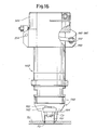
- the arrangement of the assembly 142 is similar to the one already described in relation to the previous example.
- the mechanical hand 140 that is fitted into the seat 180 is different and in the drawing the same members are indicated by the same references as those of the preceding case.
- the shank 184 of a body 186 of the mechanical hand holding the tool, or the operative replaceable fixture is fitted which in this example is shown as performing an insertion.
- a sensor 187 (see Fig.18) which is housed in the piece 142B and appears at the level of the surface which comes in contact with the piece 186 of the mechanical hand 140; the possible grip failure of the grip or the mechanical hand loss is thereby signalled.
- a through seat 188 is predisposed which is longitudinally crossed by a manoeuvre column 190 reaching the very tool 192 in order to drive the operative members thereof; the toot is replaceable on the mechanical hand 14 0 respectively with the mechanical hand 140.
- the tool 192 comprises a mobile operative member 194 which is slidingly driven by the manoeuvring column 190- According to the diagram of Figs.13, 16, 17, the mobile member 194 acts on a component CO which has rheophores RE intended to be inserted into the holes FO of a card SC.
- the top of column 190 is received in the dead axial end hole 168A of the sensor stem 168.
- This column 190 is at least partly threaded to engage an adjustable pawl 196 practically made up of a nut and a lock nut
- a spring 198 from down upwards acts, reacting on the body of the mobile or mechanical hand 140, that is on the tool 192, while, on the adjustable pawl 196 -after an adjustable run -both the lower end of the sensor stem 168 and the lower end of the stem 176 of the power piston 172, can act from up downwards.
- the assembly 190, 196 makes up the manoeuvre member of the mechanical hand.
- the arrangement is such that the power piston 172 intended to carry out the operation, for example, of applying a component to a card, comes into action only if the operation can be done without meeting a resistance greater than a certain limit, since a higher resistance would involve the risk or the certainty of a damage in the component to be applied or in the support to which it is to be applied or, anyway, of an incorrect operation-
- the mechanical hand has been placed in an operative position - the lever 152 being in the lifted position shown in Fig-14 - the small piston 164 is urged causing .the towering of the lever 152.
- the lever 152 may duly lower around its articulation 154 as the lower end of the sensor stem 158, by acting on the pawl 196, lowers the column 190 until the rheophores RE of component CO go into the seats FO suitably predisposed in the card support SC or the like (see Fig.14). Under these conditions, the displacement of the lever element 152 is such as to cause the interception of the optical sight 1 60, 162 and to determine therefore a consensus to the activation of the power piston system 170, 172.
- This activation causes the lowering of the power piston 172 and of its tubular stem 176 which comes in contact with the adjustable pawl 196 and causes the operative run of column 190 and mobile members 19 4 of the tool 192 to complete the operation established for the applied mechanical hand 140, in this example, the operation of the complete insertion of rheophores RE into the holes FO.
- the force exerted on the sensor stem 168 is, however, so limited so as to avoid any kind of damage to the component (like CO, RE) which should have been applied, as well as to the members of the mechanical hand or, in any case, of the apparatus.
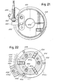
- numeral 401 indicates the fitting block having a seat 402 for the fitting on the head of the end of the robot arm, to which seat said block can be tightened for example, by the tangential screw 403.
- a diametral seat 404 is formed for a lever 405 having its fulcrum at 406 and cooperating with an axial sensor to be described below.
- the lower portion 401A of block 401 forms a cylindrical cavity 407 into which a single- acting piston 4 1 0 can slide -with a feeding connection 4 1 1 and with a spring -(or a double-acting piston), whose stem 410A slides through a block 414 to reach a cavity 416, which serves to fit the shank 418 of the very toot U.
- This shank 418 has an angular groove 418A having isosceles triangle outline and, however, with a conical bank 4 1 8B for the purposes indicated below.
- the block 414 is secured to the block 4 01, 4 0 1 A by means of screws 420.
- three cylindrical radial seats 422 are formed, which enter the cavity 41 6 with a slight reduction in diameter formed in each seat 422 by a small collar 422A; this collar is apt to retain a tem of balls 424 which is housed in the respective seat 422 being axially mobile therein.
- the balls 4 24 may project in the cavity 416 to retain the shank 418 by acting on the truncated-cone wall 4 1 8B.
- the shank 418 is therefore centrally retained by the centripetal thrust of the three terns of balls 424.
- a fluid-operated control system is provided -and in particular, compressed air-operated - which is described below.
- the block 414 makes up -with its outer cylindrical skirt 414A -the inner face of an annular cylinder whose outer concave surface 426A is formed by a piece 426 which is fitted on the block 401 and tightened between this block and the block 414 by the screws 420.
- the two cylindrical surfaces 414A and 426A form a cylinder of annular section completed by the annular cavity 426B which is formed in the piece 426 and can be reached by the control fluid fed through a connection 428.
- Numerals 430 and 432 indicate two seals cooperating to assure a sealing condition between the above described cylinder having annular section and an annular piston 434 which is slidingly inserted in this cylinder.
- the piston 434 is urged by three springs 436, which are housed within axial holes evenly distributed on the piston 434 and which react on a lower end flange 414C of block 4 14, this flange being lined up with the three radial seats 422.
- the annular piston 434 has in its lower part an inner conical surface 434A which comes in contact with the outer ball of each of the three terns of balls 424 housed in the three seats 422.
- the arrangement is such that, by feeding fluid under pressure from the connection 4 28 to the - cavity 426B and then into the cylinder with annular section, the piston 434 is pushed downwards against the action" of springs 436 and caused to push -through the truncated-cone surface 434A -the balls 424 in the centripetal direction in order to engage with the inner-most balls the surface 418B of groove 418A of the tool shank 418, if present, and to block the latter with a relatively strong force.
- the described locking device permits to quickly release a tool U associated with the shank 41 8 and the lock, in a very strong and self-centering manner, the shank and thus the tool, by also axially forcing it against the surface 414E. All that is obtained together with a high retaining power, very limited dimensions and through a device of low cost servicing and relatively economical production.
- the tool rests against the lower surface 414E of the block 414 and is centered by the presence of a pin 440 which may have a seat in a suitable housing 442 of the support surface of tool U against the surface 414E.
- a pin 440 which may have a seat in a suitable housing 442 of the support surface of tool U against the surface 414E.
- a passage 446 is dug in which an axial sensor stem 450 slides projecting downwards into the cavity 4 16 and acting with its upper part on the lever 405 against the action of a small spring such as a pneumatic spring generated by a small piston 452 which can also act as a position sensor of the lever 4 0 5 .
- the outer mobile end of lever 405 cooperates with a proximity sensor 452 which controls the lower position and the lifting of the lever and thus of the sensor. This allows to evaluate the presence of the shank 418 or even to sense the possible initial resistance to the insertion of a component on its support, prior to the intervention of the power actuator controlled by piston 410, 410A.
- Another sensor 456 is provided for detecting, on the surface 414E, the presence of the contacting surface of tool U.
- Still another sensor 458 may be provided in a side body 460; said sensor cooperates with an external appendix 434E of the annular piston 434 to indicate the position of the latter, in order to evaluate the release conditions of the clamp.
Priority Applications (1)
| Application Number | Priority Date | Filing Date | Title |
|---|---|---|---|
| AT86830026T ATE45534T1 (de) | 1985-02-04 | 1986-02-03 | Einrichtung zum automatisieren von operativen systemen mit mechanischer hand oder dergleichen. |
Applications Claiming Priority (4)
| Application Number | Priority Date | Filing Date | Title |
|---|---|---|---|
| IT932985 | 1985-02-04 | ||
| IT09329/85A IT1201226B (it) | 1985-02-04 | 1985-02-04 | Attrezzatura per l'automazione di sistemi operativi a mano meccanica o simili,con sensore atto a rilevare condizioni anomale |
| IT938685 | 1985-04-17 | ||
| IT09386/85A IT1201272B (it) | 1985-04-17 | 1985-04-17 | Attrezzo per il bloccaggio di un utensile sul braccio di un robot e per altri impieghi |
Publications (2)
| Publication Number | Publication Date |
|---|---|
| EP0194234A1 true EP0194234A1 (de) | 1986-09-10 |
| EP0194234B1 EP0194234B1 (de) | 1989-08-16 |
Family
ID=26326177
Family Applications (1)
| Application Number | Title | Priority Date | Filing Date |
|---|---|---|---|
| EP86830026A Expired EP0194234B1 (de) | 1985-02-04 | 1986-02-03 | Einrichtung zum Automatisieren von operativen Systemen mit mechanischer Hand oder dergleichen |
Country Status (4)
| Country | Link |
|---|---|
| US (1) | US4733457A (de) |
| EP (1) | EP0194234B1 (de) |
| DE (1) | DE3665037D1 (de) |
| ES (1) | ES8701009A1 (de) |
Cited By (8)
| Publication number | Priority date | Publication date | Assignee | Title |
|---|---|---|---|---|
| EP0274056A1 (de) * | 1986-12-17 | 1988-07-13 | Siemens Aktiengesellschaft | Robotergreifer |
| EP0309613A1 (de) * | 1987-10-02 | 1989-04-05 | Höfler & Kobler Handhabungsautomaten | Parallelführung von Linearantrieben |
| EP0386729A1 (de) * | 1989-03-09 | 1990-09-12 | EDAG Engineering + Design Aktiengesellschaft | Bei Überlast selbsttätig ausrastbare hydraulische Kupplung |
| DE4004738A1 (de) * | 1990-01-25 | 1991-08-08 | Maag Zahnraeder & Maschinen Ag | Greiferbaugruppe |
| WO1992017321A1 (de) * | 1991-04-06 | 1992-10-15 | Robert Bosch Gmbh | Druckmittelbetätigte lineareinheit |
| DE4202856A1 (de) * | 1992-02-01 | 1993-08-05 | Bodenseewerk Geraetetech | Parallelgreifer, zum beispiel fuer roboter |
| CN111115227A (zh) * | 2019-12-19 | 2020-05-08 | 南京涵铭置智能科技有限公司 | 一种玻璃瓶夹持机构及其夹持方法 |
| CN112792805A (zh) * | 2021-01-12 | 2021-05-14 | 广东智源机器人科技有限公司 | 机械爪装置 |
Families Citing this family (10)
| Publication number | Priority date | Publication date | Assignee | Title |
|---|---|---|---|---|
| FR2680128B1 (fr) * | 1991-08-05 | 1994-12-23 | Philippe Roudaut | Pince pneumatique et, plus particulierement, une pince pneumatique du type a doigts a deplacement lineaire et parallele. |
| US5331831A (en) * | 1993-03-19 | 1994-07-26 | Bermo, Inc. | Hardware sensor |
| US7043825B2 (en) * | 2003-02-17 | 2006-05-16 | Komax Holding Ag | Cable-processing device |
| EP1447888B1 (de) * | 2003-02-17 | 2014-12-10 | Komax Holding AG | Greifer für eine Kabelbearbeitungseinrichtung |
| DE50312360D1 (de) * | 2003-08-09 | 2010-03-11 | Trumpf Werkzeugmaschinen Gmbh | Laserbearbeitungsdüsenkupplung |
| US7971594B2 (en) * | 2008-04-04 | 2011-07-05 | Belanger, Inc. | Pendulum-type wheel washer |
| JP6030718B1 (ja) * | 2015-07-03 | 2016-11-24 | 上銀科技股▲分▼有限公司 | 末端効果器を交換する機械式交換装置 |
| CN110270873A (zh) * | 2019-07-27 | 2019-09-24 | 重庆第二机床厂有限责任公司 | 机床送料装置 |
| CA203911S (en) * | 2021-06-03 | 2023-05-31 | Macdonald Dettwiler & Associates Inc | Robotic end effector and end of arm tool |
| CA203910S (en) * | 2021-06-03 | 2023-05-30 | Macdonald Dettwiler & Associates Inc | Robotic end effector and end of arm tool |
Citations (8)
| Publication number | Priority date | Publication date | Assignee | Title |
|---|---|---|---|---|
| DE1054736B (de) * | 1958-06-12 | 1959-04-09 | Gen Mills Inc | Verfahren und Vorrichtung zur akustischen Greifkraft- und Freigabeanzeige |
| DE2443962A1 (de) * | 1973-09-14 | 1975-03-20 | Komatsu Mfg Co Ltd | Greifvorrichtung |
| FR2265495A1 (en) * | 1974-03-27 | 1975-10-24 | Est Aciers Fins | Hydraulically operated mechanical handling pincer - uses two double acting rams to advance and operate the grip |
| GB1578340A (en) * | 1977-11-15 | 1980-11-05 | Normalair Garrett Ltd | Mechanical hands eg for diving apparatus |
| EP0092967A2 (de) * | 1982-04-27 | 1983-11-02 | Fanuc Ltd. | Automatische Greifhand-Wechselvorrichtung für Industrieroboter |
| GB2118522A (en) * | 1982-04-16 | 1983-11-02 | Messerschmitt Boelkow Blohm | A two part connection having a taper sleeve and a taper shank |
| GB2134073A (en) * | 1983-01-28 | 1984-08-08 | Westinghouse Electric Corp | A multi-lead component manipulator |
| US4532757A (en) * | 1983-09-30 | 1985-08-06 | Martin Marietta Corporation | Robotic fruit harvester |
Family Cites Families (11)
| Publication number | Priority date | Publication date | Assignee | Title |
|---|---|---|---|---|
| US3881604A (en) * | 1973-05-11 | 1975-05-06 | Cincinnati Milacron Inc | Machine loader pickup device |
| US3932931A (en) * | 1973-06-08 | 1976-01-20 | Elco Corporation | Post terminal insertion method and apparatus |
| US3968555A (en) * | 1974-08-26 | 1976-07-13 | Bunker Ramo Corporation | Electrically operated programmable insertion tool with conductor guide and movable strain relief insertion mechanisms |
| US4171821A (en) * | 1978-02-16 | 1979-10-23 | Chamberlain Manufacturing Company | Quick change collet tool holder assembly |
| JPS55108796A (en) * | 1979-02-14 | 1980-08-21 | Matsushita Electric Ind Co Ltd | Device for inserting component |
| US4327483A (en) * | 1979-06-07 | 1982-05-04 | Universal Instruments Corporation | Apparatus for selecting, transporting, and inserting single in-line components |
| US4290617A (en) * | 1979-06-11 | 1981-09-22 | The Boeing Company | Motor quick-change chuck system for tool having cylindrically shaped adapter portion wherein relative longitudinal movement between chuck and tool being driven is eliminated |
| US4464833A (en) * | 1982-09-01 | 1984-08-14 | Usm Corporation | Variable rate control logic for component insertion machine |
| US4499800A (en) * | 1983-04-04 | 1985-02-19 | General Electric Company | Tool holder clamping means |
| US4510683A (en) * | 1983-10-27 | 1985-04-16 | Sperry Corporation | Force assembler apparatus for robots |
| US4611397A (en) * | 1984-10-09 | 1986-09-16 | Universal Instruments Corporation | Pick and place method and apparatus for handling electrical components |
-
1986
- 1986-01-29 US US06/823,997 patent/US4733457A/en not_active Expired - Fee Related
- 1986-02-03 DE DE8686830026T patent/DE3665037D1/de not_active Expired
- 1986-02-03 EP EP86830026A patent/EP0194234B1/de not_active Expired
- 1986-02-03 ES ES551573A patent/ES8701009A1/es not_active Expired
Patent Citations (8)
| Publication number | Priority date | Publication date | Assignee | Title |
|---|---|---|---|---|
| DE1054736B (de) * | 1958-06-12 | 1959-04-09 | Gen Mills Inc | Verfahren und Vorrichtung zur akustischen Greifkraft- und Freigabeanzeige |
| DE2443962A1 (de) * | 1973-09-14 | 1975-03-20 | Komatsu Mfg Co Ltd | Greifvorrichtung |
| FR2265495A1 (en) * | 1974-03-27 | 1975-10-24 | Est Aciers Fins | Hydraulically operated mechanical handling pincer - uses two double acting rams to advance and operate the grip |
| GB1578340A (en) * | 1977-11-15 | 1980-11-05 | Normalair Garrett Ltd | Mechanical hands eg for diving apparatus |
| GB2118522A (en) * | 1982-04-16 | 1983-11-02 | Messerschmitt Boelkow Blohm | A two part connection having a taper sleeve and a taper shank |
| EP0092967A2 (de) * | 1982-04-27 | 1983-11-02 | Fanuc Ltd. | Automatische Greifhand-Wechselvorrichtung für Industrieroboter |
| GB2134073A (en) * | 1983-01-28 | 1984-08-08 | Westinghouse Electric Corp | A multi-lead component manipulator |
| US4532757A (en) * | 1983-09-30 | 1985-08-06 | Martin Marietta Corporation | Robotic fruit harvester |
Cited By (9)
| Publication number | Priority date | Publication date | Assignee | Title |
|---|---|---|---|---|
| EP0274056A1 (de) * | 1986-12-17 | 1988-07-13 | Siemens Aktiengesellschaft | Robotergreifer |
| EP0309613A1 (de) * | 1987-10-02 | 1989-04-05 | Höfler & Kobler Handhabungsautomaten | Parallelführung von Linearantrieben |
| EP0386729A1 (de) * | 1989-03-09 | 1990-09-12 | EDAG Engineering + Design Aktiengesellschaft | Bei Überlast selbsttätig ausrastbare hydraulische Kupplung |
| DE4004738A1 (de) * | 1990-01-25 | 1991-08-08 | Maag Zahnraeder & Maschinen Ag | Greiferbaugruppe |
| WO1992017321A1 (de) * | 1991-04-06 | 1992-10-15 | Robert Bosch Gmbh | Druckmittelbetätigte lineareinheit |
| US5305683A (en) * | 1991-04-06 | 1994-04-26 | Robert Bosch Gmbh | Pressure-medium actuated linear unit |
| DE4202856A1 (de) * | 1992-02-01 | 1993-08-05 | Bodenseewerk Geraetetech | Parallelgreifer, zum beispiel fuer roboter |
| CN111115227A (zh) * | 2019-12-19 | 2020-05-08 | 南京涵铭置智能科技有限公司 | 一种玻璃瓶夹持机构及其夹持方法 |
| CN112792805A (zh) * | 2021-01-12 | 2021-05-14 | 广东智源机器人科技有限公司 | 机械爪装置 |
Also Published As
| Publication number | Publication date |
|---|---|
| ES551573A0 (es) | 1986-11-16 |
| US4733457A (en) | 1988-03-29 |
| ES8701009A1 (es) | 1986-11-16 |
| DE3665037D1 (en) | 1989-09-21 |
| EP0194234B1 (de) | 1989-08-16 |
Similar Documents
| Publication | Publication Date | Title |
|---|---|---|
| EP0194234A1 (de) | Einrichtung zum Automatisieren von operativen Systemen mit mechanischer Hand oder dergleichen | |
| US4878705A (en) | Robot gripper passively locked | |
| CA1270501A (en) | Interchangeable tool mounting mechanism for robots | |
| US4573271A (en) | Machine performance sensor | |
| US6202290B1 (en) | Pressing device for joining workpieces | |
| US4782726A (en) | Lead screw driver | |
| US5277689A (en) | Tool changer for tools of a machine tool | |
| JPH0253199B2 (de) | ||
| US4715636A (en) | Gripper including an exchangeable gripping jaw | |
| JPH08187627A (ja) | 止水栓の自動ねじ締め装置 | |
| US6240807B1 (en) | Indexing apparatus | |
| TW202243789A (zh) | 監測配置、具有監測配置之夾緊系統、以及藉由監測配置監測夾緊裝置之方法 | |
| US4669192A (en) | Variable compliance device | |
| US5326123A (en) | Connector assembly | |
| WO2020225613A1 (en) | Industrial manipulator gripper provided with sensor and method for detecting the presence of a piece between the jaws of an industrial manipulator gripper | |
| EP0636450B1 (de) | Spannvorrichtung | |
| CN115415787A (zh) | 一种防爆型自动装配专机系统 | |
| KR940007174B1 (ko) | 큰치수 보울트의 이상적인 나사체결 위치 설정방법 및 장치 | |
| US6608958B2 (en) | Centralizing clamp for an optical fiber | |
| CA2011849A1 (en) | Breakaway clutch device | |
| CA2409371C (en) | Tubular joint detection system | |
| CA1310597C (en) | Air clutch with tool changer | |
| CN114310251B (zh) | 卡簧自动压装检测装置 | |
| CN112037940B (zh) | 内置式控制棒驱动线有限空间安装方法 | |
| US4327261A (en) | Apparatus for sensing a distended location on a drill pipe |
Legal Events
| Date | Code | Title | Description |
|---|---|---|---|
| PUAI | Public reference made under article 153(3) epc to a published international application that has entered the european phase |
Free format text: ORIGINAL CODE: 0009012 |
|
| AK | Designated contracting states |
Kind code of ref document: A1 Designated state(s): AT BE CH DE FR GB LI LU NL SE |
|
| 17P | Request for examination filed |
Effective date: 19870122 |
|
| 17Q | First examination report despatched |
Effective date: 19880210 |
|
| RAP3 | Party data changed (applicant data changed or rights of an application transferred) |
Owner name: MGZ S.P.A. |
|
| GRAA | (expected) grant |
Free format text: ORIGINAL CODE: 0009210 |
|
| STAA | Information on the status of an ep patent application or granted ep patent |
Free format text: STATUS: THE PATENT HAS BEEN GRANTED |
|
| AK | Designated contracting states |
Kind code of ref document: B1 Designated state(s): AT BE CH DE FR GB LI LU NL SE |
|
| PG25 | Lapsed in a contracting state [announced via postgrant information from national office to epo] |
Ref country code: LI Effective date: 19890816 Ref country code: CH Effective date: 19890816 Ref country code: AT Effective date: 19890816 |
|
| REF | Corresponds to: |
Ref document number: 45534 Country of ref document: AT Date of ref document: 19890915 Kind code of ref document: T |
|
| REF | Corresponds to: |
Ref document number: 3665037 Country of ref document: DE Date of ref document: 19890921 |
|
| REG | Reference to a national code |
Ref country code: CH Ref legal event code: PL |
|
| ET | Fr: translation filed | ||
| PG25 | Lapsed in a contracting state [announced via postgrant information from national office to epo] |
Ref country code: LU Free format text: LAPSE BECAUSE OF NON-PAYMENT OF DUE FEES Effective date: 19900228 |
|
| PLBE | No opposition filed within time limit |
Free format text: ORIGINAL CODE: 0009261 |
|
| 26N | No opposition filed | ||
| PGFP | Annual fee paid to national office [announced via postgrant information from national office to epo] |
Ref country code: SE Payment date: 19910109 Year of fee payment: 6 |
|
| PGFP | Annual fee paid to national office [announced via postgrant information from national office to epo] |
Ref country code: FR Payment date: 19910118 Year of fee payment: 6 |
|
| PGFP | Annual fee paid to national office [announced via postgrant information from national office to epo] |
Ref country code: GB Payment date: 19910122 Year of fee payment: 6 |
|
| PGFP | Annual fee paid to national office [announced via postgrant information from national office to epo] |
Ref country code: NL Payment date: 19910228 Year of fee payment: 6 |
|
| PGFP | Annual fee paid to national office [announced via postgrant information from national office to epo] |
Ref country code: BE Payment date: 19910415 Year of fee payment: 6 |
|
| PGFP | Annual fee paid to national office [announced via postgrant information from national office to epo] |
Ref country code: DE Payment date: 19910423 Year of fee payment: 6 |
|
| PG25 | Lapsed in a contracting state [announced via postgrant information from national office to epo] |
Ref country code: GB Effective date: 19920203 |
|
| PG25 | Lapsed in a contracting state [announced via postgrant information from national office to epo] |
Ref country code: SE Effective date: 19920204 |
|
| PG25 | Lapsed in a contracting state [announced via postgrant information from national office to epo] |
Ref country code: BE Effective date: 19920228 |
|
| BERE | Be: lapsed |
Owner name: MGZ S.P.A. Effective date: 19920228 |
|
| PG25 | Lapsed in a contracting state [announced via postgrant information from national office to epo] |
Ref country code: NL Effective date: 19920901 |
|
| GBPC | Gb: european patent ceased through non-payment of renewal fee | ||
| NLV4 | Nl: lapsed or anulled due to non-payment of the annual fee | ||
| PG25 | Lapsed in a contracting state [announced via postgrant information from national office to epo] |
Ref country code: FR Effective date: 19921030 |
|
| PG25 | Lapsed in a contracting state [announced via postgrant information from national office to epo] |
Ref country code: DE Effective date: 19921103 |
|
| REG | Reference to a national code |
Ref country code: FR Ref legal event code: ST |
|
| EUG | Se: european patent has lapsed |
Ref document number: 86830026.0 Effective date: 19920904 |