EP0194008A2 - Herstellen von Papierblättern mit dekorativen nichtgeradlinigen Rändern - Google Patents
Herstellen von Papierblättern mit dekorativen nichtgeradlinigen Rändern Download PDFInfo
- Publication number
- EP0194008A2 EP0194008A2 EP86300328A EP86300328A EP0194008A2 EP 0194008 A2 EP0194008 A2 EP 0194008A2 EP 86300328 A EP86300328 A EP 86300328A EP 86300328 A EP86300328 A EP 86300328A EP 0194008 A2 EP0194008 A2 EP 0194008A2
- Authority
- EP
- European Patent Office
- Prior art keywords
- web
- sheet
- edge
- sheets
- trimming
- Prior art date
- Legal status (The legal status is an assumption and is not a legal conclusion. Google has not performed a legal analysis and makes no representation as to the accuracy of the status listed.)
- Ceased
Links
Images


Classifications
-
- B—PERFORMING OPERATIONS; TRANSPORTING
- B65—CONVEYING; PACKING; STORING; HANDLING THIN OR FILAMENTARY MATERIAL
- B65H—HANDLING THIN OR FILAMENTARY MATERIAL, e.g. SHEETS, WEBS, CABLES
- B65H35/00—Delivering articles from cutting or line-perforating machines; Article or web delivery apparatus incorporating cutting or line-perforating devices, e.g. adhesive tape dispensers
-
- B—PERFORMING OPERATIONS; TRANSPORTING
- B24—GRINDING; POLISHING
- B24B—MACHINES, DEVICES, OR PROCESSES FOR GRINDING OR POLISHING; DRESSING OR CONDITIONING OF ABRADING SURFACES; FEEDING OF GRINDING, POLISHING, OR LAPPING AGENTS
- B24B19/00—Single-purpose machines or devices for particular grinding operations not covered by any other main group
- B24B19/22—Single-purpose machines or devices for particular grinding operations not covered by any other main group characterised by a special design with respect to properties of the material of non-metallic articles to be ground
- B24B19/223—Single-purpose machines or devices for particular grinding operations not covered by any other main group characterised by a special design with respect to properties of the material of non-metallic articles to be ground of paper or similar sheet material, e.g. perforating, cutting by means of a grinding wheel
-
- B—PERFORMING OPERATIONS; TRANSPORTING
- B26—HAND CUTTING TOOLS; CUTTING; SEVERING
- B26F—PERFORATING; PUNCHING; CUTTING-OUT; STAMPING-OUT; SEVERING BY MEANS OTHER THAN CUTTING
- B26F3/00—Severing by means other than cutting; Apparatus therefor
- B26F3/02—Tearing
-
- B—PERFORMING OPERATIONS; TRANSPORTING
- B44—DECORATIVE ARTS
- B44C—PRODUCING DECORATIVE EFFECTS; MOSAICS; TARSIA WORK; PAPERHANGING
- B44C1/00—Processes, not specifically provided for elsewhere, for producing decorative surface effects
- B44C1/22—Removing surface-material, e.g. by engraving, by etching
- B44C1/225—Removing surface-material, e.g. by engraving, by etching by engraving
-
- B—PERFORMING OPERATIONS; TRANSPORTING
- B65—CONVEYING; PACKING; STORING; HANDLING THIN OR FILAMENTARY MATERIAL
- B65H—HANDLING THIN OR FILAMENTARY MATERIAL, e.g. SHEETS, WEBS, CABLES
- B65H35/00—Delivering articles from cutting or line-perforating machines; Article or web delivery apparatus incorporating cutting or line-perforating devices, e.g. adhesive tape dispensers
- B65H35/10—Delivering articles from cutting or line-perforating machines; Article or web delivery apparatus incorporating cutting or line-perforating devices, e.g. adhesive tape dispensers from or with devices for breaking partially-cut or perforated webs, e.g. bursters
-
- Y—GENERAL TAGGING OF NEW TECHNOLOGICAL DEVELOPMENTS; GENERAL TAGGING OF CROSS-SECTIONAL TECHNOLOGIES SPANNING OVER SEVERAL SECTIONS OF THE IPC; TECHNICAL SUBJECTS COVERED BY FORMER USPC CROSS-REFERENCE ART COLLECTIONS [XRACs] AND DIGESTS
- Y10—TECHNICAL SUBJECTS COVERED BY FORMER USPC
- Y10T—TECHNICAL SUBJECTS COVERED BY FORMER US CLASSIFICATION
- Y10T225/00—Severing by tearing or breaking
- Y10T225/10—Methods
- Y10T225/14—Longitudinally of direction of feed
-
- Y—GENERAL TAGGING OF NEW TECHNOLOGICAL DEVELOPMENTS; GENERAL TAGGING OF CROSS-SECTIONAL TECHNOLOGIES SPANNING OVER SEVERAL SECTIONS OF THE IPC; TECHNICAL SUBJECTS COVERED BY FORMER USPC CROSS-REFERENCE ART COLLECTIONS [XRACs] AND DIGESTS
- Y10—TECHNICAL SUBJECTS COVERED BY FORMER USPC
- Y10T—TECHNICAL SUBJECTS COVERED BY FORMER US CLASSIFICATION
- Y10T225/00—Severing by tearing or breaking
- Y10T225/30—Breaking or tearing apparatus
- Y10T225/307—Combined with preliminary weakener or with nonbreaking cutter
-
- Y—GENERAL TAGGING OF NEW TECHNOLOGICAL DEVELOPMENTS; GENERAL TAGGING OF CROSS-SECTIONAL TECHNOLOGIES SPANNING OVER SEVERAL SECTIONS OF THE IPC; TECHNICAL SUBJECTS COVERED BY FORMER USPC CROSS-REFERENCE ART COLLECTIONS [XRACs] AND DIGESTS
- Y10—TECHNICAL SUBJECTS COVERED BY FORMER USPC
- Y10T—TECHNICAL SUBJECTS COVERED BY FORMER US CLASSIFICATION
- Y10T225/00—Severing by tearing or breaking
- Y10T225/30—Breaking or tearing apparatus
- Y10T225/336—Conveyor diverter for moving work
- Y10T225/343—Plural divergent work paths
-
- Y—GENERAL TAGGING OF NEW TECHNOLOGICAL DEVELOPMENTS; GENERAL TAGGING OF CROSS-SECTIONAL TECHNOLOGIES SPANNING OVER SEVERAL SECTIONS OF THE IPC; TECHNICAL SUBJECTS COVERED BY FORMER USPC CROSS-REFERENCE ART COLLECTIONS [XRACs] AND DIGESTS
- Y10—TECHNICAL SUBJECTS COVERED BY FORMER USPC
- Y10T—TECHNICAL SUBJECTS COVERED BY FORMER US CLASSIFICATION
- Y10T83/00—Cutting
- Y10T83/202—With product handling means
- Y10T83/2092—Means to move, guide, or permit free fall or flight of product
- Y10T83/22—Means to move product laterally
- Y10T83/2205—Reciprocating means
-
- Y—GENERAL TAGGING OF NEW TECHNOLOGICAL DEVELOPMENTS; GENERAL TAGGING OF CROSS-SECTIONAL TECHNOLOGIES SPANNING OVER SEVERAL SECTIONS OF THE IPC; TECHNICAL SUBJECTS COVERED BY FORMER USPC CROSS-REFERENCE ART COLLECTIONS [XRACs] AND DIGESTS
- Y10—TECHNICAL SUBJECTS COVERED BY FORMER USPC
- Y10T—TECHNICAL SUBJECTS COVERED BY FORMER US CLASSIFICATION
- Y10T83/00—Cutting
- Y10T83/202—With product handling means
- Y10T83/2092—Means to move, guide, or permit free fall or flight of product
- Y10T83/2207—Means to move product in a nonrectilinear path
-
- Y—GENERAL TAGGING OF NEW TECHNOLOGICAL DEVELOPMENTS; GENERAL TAGGING OF CROSS-SECTIONAL TECHNOLOGIES SPANNING OVER SEVERAL SECTIONS OF THE IPC; TECHNICAL SUBJECTS COVERED BY FORMER USPC CROSS-REFERENCE ART COLLECTIONS [XRACs] AND DIGESTS
- Y10—TECHNICAL SUBJECTS COVERED BY FORMER USPC
- Y10T—TECHNICAL SUBJECTS COVERED BY FORMER US CLASSIFICATION
- Y10T83/00—Cutting
- Y10T83/647—With means to convey work relative to tool station
- Y10T83/6476—Including means to move work from one tool station to another
- Y10T83/6478—Tool stations angularly related
- Y10T83/648—Work manipulated between tool stations
-
- Y—GENERAL TAGGING OF NEW TECHNOLOGICAL DEVELOPMENTS; GENERAL TAGGING OF CROSS-SECTIONAL TECHNOLOGIES SPANNING OVER SEVERAL SECTIONS OF THE IPC; TECHNICAL SUBJECTS COVERED BY FORMER USPC CROSS-REFERENCE ART COLLECTIONS [XRACs] AND DIGESTS
- Y10—TECHNICAL SUBJECTS COVERED BY FORMER USPC
- Y10T—TECHNICAL SUBJECTS COVERED BY FORMER US CLASSIFICATION
- Y10T83/00—Cutting
- Y10T83/647—With means to convey work relative to tool station
- Y10T83/6476—Including means to move work from one tool station to another
- Y10T83/6489—Slitter station
- Y10T83/6491—And transverse cutter station
Definitions
- This invention relates to the trimming of paper webs, particularly in the production of paper in sheet or web form, more especialy writing paper, with decorative, non-rectilinear edges, e.g. of a deckled nature.
- the present invention provides a method of trimming a travelling web of paper along the longitudinal direction of the web comprising transporting the web through a trimming station and continuously trimming said web in said station, wherein said method comprises supporting a portion of said web on a support surface in said station such that a portion of said web to be trimmed off overhangs an edge of said support surface, contacting said overhanging portion of said web with a travelling endless member which crosses the edge of the said support surface to trap the overhanging portion of the web between the endless member and a tearing support member adjacent said edge to shear said overhanging portion continuously from the web.
- said web overhangs said support surface on both sides of the web and a said travelling endless member and tearing support member are provided on each longitudinal side of the support surface to trim both sides of the web.
- the web passes beneath at least one hold down member in said station and is held thereby against the support surface.
- the travelling endless member follows a run which includes a portion underlying a said hold down member and said web is pinched between the travelling endless member and the support surface.
- the portions of-the web trimmed off in said trimming station are continuously removed by suction through at least one collection duct
- the web may be separated into sheets.
- said web is intermittently compressed along a line extending transversely of the web to produce a line of weakness and is torn along said line of weakness to produce said sheets.
- Said tearing may be carried out by engaging the web between first and second pairs of opposed rollers at foca- tions, spaced in the web travel direction, the downstream pair of rollers rotating in the web travel direction constantly or intermittently faster than the upstream pair.
- said downstream pair of rollers intermittently are rotating slower than said upstream pair and interm i t-tently faster than said upstream pair so as to slacken and tighten the web to produce tearing along said lines of weakness.
- the sheets may then be conveyed to a device which changes the orientation of the sheets with respect to their direction of travel by 90° so that those edges which were trimmed longitudinally prior to separation of the web into sheets become transverse to the direction of travel.
- Such a device for changing the direction of sheet orientation with respect to the direction of travel may operate by changing the direction of sheet travel by 90° while leaving the orientation of the sheets with respect to the web travel direction unaltered.
- the change in travel direction may be accomplished by depositing each sheet between radial arms of a star wheel comprising a hub and a plurality of radial arms extending therefrom, the arms being suitably provided by coplanar sets of rods, each sheet being deposited in a radial direction with respect to said hub, and removing each sheet from said star wheel in a direction parallel to the axis of said hub.
- the sheets may be conveyed in their new travel orientation to a second trimming station for the trimming of one or both edges.
- each travelling sheet may be supported on a support surface in said station such that a portion to be trimmed off overhangs an edge of said support surface, and said overhanging portion may be contacted with a travelling endless member which crosses the edge of said support surface to trap the overhanging portion of the sheet between the endless member and a tearing support member adjacent said edge to shear said overhanging portion continuously from the sheet
- each sheet overhangs said support surface on both sides of the sheet and a said travelling endless member and tearing support member are provided on each longitudinal side of the support surface to trim both sides of the sheet
- the sheets may be transported through said second trimming station between a pair of endless belts, one of which constitutes the said support surface of said station.
- the or each said endless travelling member is a belt and preferably, the or each tearing support member is a roller.
- the position of the or each tearing support member is preferably adjustable.
- the position of the or each tearing support member is adjustable laterally of the respective support surface and/or in a direction perpendicular to said support surface.
- Edge zones of the trimmed web and/or edge zones of the trimmed sheets may be further trimmed in the longitudi- naf direction of the respective edge to remove any excessively protruding areas.
- Areas of said web may be provided with water marks or areas of differential thickness, translucency and/or texture visually resembling water marks (psuedo-water marks).
- said webs are provided with psuedo-water marks by abrading a surface of the web with an abrading member whilst supporting the web against a 3-dimensionally patterned support member.
- the appearance of the final product may be enhanced if the water marks or psuedo-water marks form lines along each edge of the web along which the web is trimmed and/or lines across the web along which the web is separated into sheets.
- the invention includes apparatus for trimming a travelling web of paper along the longitudinal direction of the web comprising a trimming station, means for transporting a web to be trimmed through the trimming station, a support surface in said station for supporting a portion of said web such that a portion of said web to be trimmed off may overhang an edge of said support surface, a travelling endless member which crosses the edge of the said support surface, and a tearing support member adjacent said edge and opposing a portion of the run of the endless travelling member whereby in use said travelling endless member contacts said overhanging portion of said web, to trap the overhanging portion of the web between the endless member and the tearing support member adjacent said edge to shear said overhanging portion continuously from the web.
- the apparatus is adapted to operate according to the preferred methods described above.
- a paper web 2 which is slightly wider than the desired width of the finished sheet is reeled off a magazine roll 1 and is passed over a deflection roller 3. Since the paper web 2, which is stored on the roll acquires a tendency to curl up, the paper web 2 is drawn through a so-called decurling device 25 consisting of two pairs of rollers placed at a distance from each other and of . bars or guide surfaces arranged between them which are vertically adjustable and over which the web is led.
- the web 2 Owing to the web 2 being drawn over the said bars of guide surfaces, which are set in such a manner that the web obtains a tendency to curve in a direction opposite to its curling, the web will be substantially plane when it has passed through the decurling unit
- the web 2 is passed subsequently over a deflection roller 4 and up onto a matrix cylinder 5 whose function and appearance will be described in greater detail in the following under the heading of "Grinding".
- the web 2 is passed over the matrix cylinder 5 and down over a further deflection roller 7.
- a rapidly rotating grinding cylinder 6 Adjoining the matrix cylinder 5, a rapidly rotating grinding cylinder 6 is arranged with the help of which selected parts of the web 2 are ground off, so that weakening lines, folding lines, perforations or figured marks of the type of water marks are formed, which is made possible by the grinding being car- led out at varying depth on portions adjoining each other.
- the grinding is not a precondition for the function of the machine and the grinding unit may be disengaged, e.g. by removing and disconnecting the grinding cylinder 6.
- the web 2 subsequently is passed over the deflection roller 8 whereupon it is advanced to the edge tearing unit which substantially consists of an endless belt 14 which runs over the deflection rollers 11, 12 and 13 and over a tearing pulley 1 0 which is adjustable in its position.
- the function of the edge tearing will be described in greater detail in the following, but by and large the tearing is carried out so that the web 2 is conveyed over a supporting member 26, the edge zones of the web 2 intended for tearing off being covered by the tearing belts 14 along the area 27 between the deflection roller 12 and the tearing pulley 1 0.
- the central zone of the web is held down by a hold-down member 46.
- rollers 12 act as hold down members and the belts 14 pass beneath them.
- the edges of the support surface are sharpened at 57 ( Figure 2.)
- the said edge zones which are held fast between the belts 14 and the tearing pulleys 10 will be pulled along with the belts as these move down toward the deflection rollers 11, the edge zones being torn off as strips which are collected in, and sucked away through, a tubing 55.
- the edge zones of the web 2 as a result of the tearing, have obtained an uneven, decorative edge which, however, does not have a defined, matched, transverse dimension, since certain edge portions may jut out in front of the others.
- the uneven edge is trimmed with the help of cutting rollers 15 which cut away the tops of the uneven edge so that an exact transverse dimension on the web 2 is achieved.
- the web will be divided up into sheets, the transverse zones of which also have to be torn so as to obtain a decorative edge structure, and subsequently be trimmed, so that the sheet obtains a specified longitudinal dimension.
- a reading device is arranged, preferably a photocell device 16, which, e.g.
- a controller by means of which a pair of cylinders 17 provided with compression tools 18 is made to engage with the web in order to carry out a linear pressing down of the paper material across the web 2 so as to crush the paper fibres and weaken the web along the said compression zone across the longitudinal direction of the web.
- This compression arrangement 17 may be substituted in principal by a perforation device and in both cases it is the intention to weaken the strength of the paper web 2 along the processing zone.
- the paper web which normally passes freely between the cylinders 17, can be compressed in the manner indicated above in a linear zone across the web 2, the said linear compression zone always having a matched position in relation to the marks read by the photocell device 16.
- the cylinders 19 rest against each other under a certain adjustable spring force so that the paper web 2 can be introduced and pass between the cylinders 1 9 as they rotate whilst being held fast at the same time between the cylinders so that any actual sliding between the paper web 2 and the cylinders 19 cannot occur.
- the cylinders 19 are driven at a constant speed which corresponds to the speed of the web 2 in all the foregoing operations.
- the paper web 2 is introduced between a second pair of cylinders 21 which in principle is the same as the pair of cylinders 19, that is to say the driven cylinder has a rubber covering 20 whereas the other cylinder is a steel cylinder.
- the cylinders in the pair of cylinders 21 are not at a constant driving speed and their mean speed is a tittle higher than the speed of the pair of cylinders 19 with the help of a planetary gear train which is driven by a cam, coupled to the driving device for the compression cylinders 17.
- the driving speed of the cylinders 21 can be increased or diminished owing to the planetary gear train providing a periodical additional contribution to, or a reduction of, the driving speed of the cylinders 21.
- the arrangement functions in such a manner that the web 2 advanced between the cylinders 19 is fed in between the pair of cylinders 21.
- the pair of cylinders 21, however, moves in this part of the working cycle at a lower speed than the pair of cylinders 19, which means that the pair of cylinders 19 advances more of the web 2 than is taken up between the pair of cylinders 21. This means, though, that there will be a so-called "slack" on the web.
- the driving speed of the cylinders 21 is increased so that the cylinders 21 advance the web 2 at a considerably higher speed than it is advanced between the cylinders 19.
- This means that the said "slack" on the web 2 is not only compensated, but that the web 2 is pulled away so that rupture takes place in the previously mentioned weakened zones across the web 2, which were produced with the help of the compression tool 18 which is located on the cylinders 17.
- the front part of the web 2 pulled away is advanced at a higher speed that the remainder of the web which is controlled by the pair of cylinders 19 and the separated part of the web is delivered onto a conveyor 22 consisting of a number of parallel endless belts, this conveyor being driven synchronously with a take-up star wheel 56.
- Fig. 1b is shown a continuation of the machine which is set at an angle of 90° to the machine shown in Fig. l a.
- the tearing of the short sides of the separated sheets is performed so that a decorative edge zone is formed whereupon the said edge zone is trimmed to the exact longitudinal dimension of the individual sheets.
- the separated sheets are transported with the help of the stepwise rotating star wheel arrangement 56 in such a manner that the sheets are turned by 180°.
- the sheets are displaced to the right off the star wheel 56 by means of a reciprocating finger 29 which is controlled by a pneumatic or hydraulic cylinder 28 so that the sheets 43 can be inserted between two endless travelling bands 30 and 31, these bands capturing and transporting the sheets 43 between them.
- the upper band 30 runs between deflection rollers 32 and the lower band 31 runs between deflection rollers 33 and slides over a fixed base 41.
- the bands 30 and 31 can be pressed towards each other with the help of rollers 34 which act against the inside of the band 30 in the region where the two bands lie adjoining each other.
- the width of the bands 30 and 31 is less than the length of the sheets 43 so that the edge zones of the sheets 43 project beyond the bands 30 and 31.
- the sheets 43 are adjusted carefully in lateral direction so that the position of the projecting edge zones is accurately controlled.
- the individual sheets 43 are transported between the bands 31 and 30 with the said edge zones of the sheets being guided in over a belt 38 of an edge tearing device provided on each side of the apparatus.
- the edge zones of the sheets 43 will be pressed against the belts 38, one belt whereof is arranged on either side of the machine. Tearing pulleys 36 overlie each belt 38 and the edge portions of the sheets. When the edge zones of the sheets 43 approach the tearing pulleys 36 the edge zones will be taken up between the tearing pulleys 36 and the tearing belts 38 and when the tearing belts 38 are led upwards the edge zone will be torn off, whereupon the waste strip is removed by being sucked up through a tube 35.
- the tearing belts 38 are endless belts which are passed over deflection rollers 37.
- the sheets 43 After the edge tearing operation the sheets 43, now having tom edges, are conveyed past cutting discs 42 set at an accurate distance from each other, by means of which the tops of the torn edges which project beyond the nominal longitudinal dimension of the sheets 43 are cut off.
- the sheets 43 are conveyed further between the belts 30 and 31 and are deposited in a collecting device 40.
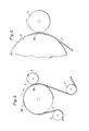
- the position of the tearing pulley 10 in relation to the position of the sharp tearing edge 57 on the supporting member 26 can be regulated and this is done with the help of an arrangement as shown in Fig. 2 and 3.
- the arrangement is constituted of a plate 48 which is supported so that it can rotate on an axle 49, this axle being parallel with the supporting surface of the supporting member 26.
- the plate 48 carries in its upper part the tearing pulley 10 which is supported so that it can rotate on an axle 47, this axle being fixed in the plate 48.
- the surface 53 can be lowered in relation to the supporting surface of the supporting member 26.
- This rotation of the plate 48 may be done e.g. in that the plate 48 is provided with a rim gear 5 1 (Fig. 3). This rim gear can be made to engage with a gear 50 which can be manoeuvred by a crank 52. Naturally the rotation of the plate may be done in any other known manner, but that given here has proved to be a simple and functional solution.
- the arrangement with the tearing pulley 10 can also be positionally adjusted in horizontal direction, that is to say a direction perpendicular to the plane of the paper in the figure shown.
- This can suitably be done in that the attachment of the axle 49 is arranged on a support which is displaceable in horizontal direction, so that it is made possible for the gap 45 between the tearing pulley 10 and the tearing edge 57 of the supporting member 26 to be adjusted to an appropriate distance, taking into account the tearing result intended and the paper quality used.
- the tearing is to be carried out this is done with the help of the endless belt 14 which runs over supporting rollers 8 and over the tearing pulley 10, this belt 14 being driven by a driving device the speed of which can be regulated.
- One part of the belt 14 is always in engagement with the edge zone of the web 2 and this part of the belt is designated 54 in Fig. 4 .
- the edge zone of the paper web 2 which is covered by the belt 14
- runs over the tearing pulley 10 the edge zone of the web 2 will be held fast between the tearing pulley 10 and the underside of the belt 14.
- the edge zone of the paper web 2 will follow, therefore, along with the belt 14 and will thus be torn off the paper web 2 and be removed as a waste strip 44 which is sucked away through a suction line 55.
- the edge 9 of the paper web 2 has obtained an uneven but decorative edge structure of the type aimed at and the appearance of this edge structure can be varied in several ways.
- the size of the gap 45 between the tearing pulley 10 and the tearing edge 57 of the supporting member 26 influences the roughness of the edge structure. If the distance 45 is adjusted to a minimum it is thus possible to obtain a near enough razor- sharp and straight cutting line which does not present any major unevennesses whereas, by contrast, an increased gap 45 gives a more uneven tearing edge.
- the tearing result can also be influenced to a large extent in that the tearing pulley in the manner described earlier is displaced vertically in relation to the tearing edge 57 of the supporting member. 26. This is done in that the plate 4 8 is rotated, so that the tearing pulley 10 by being swivelled about the axle 49 of the plate 48 will be positioned with its top surface 53 below the tearing edge 57. This means that on passing over the tearing edge 57 the paper web 2 will be curved downwards in order to lie against against the surface of the tearing pulley 1 0, and it has been found that this brings about a better controlled tearing and that in certain cases a more decorative tearing edge can be achieved in this manner.
- Another factor which affects the tearing result is the speed of the tearing belt 14.
- the tearing belt 14 should be at the same speed as the advancing paper web 2. It has been found, however, that this is not the case and a better controlled tearing is achieved if the tearing belt 14 is at a slightly higher speed (between 1 -5%) than the paper web 2. This is due probably to the tearing being facilitated by the intitiation of tensile stresses in longitudinal direction of the paper edge as well as in transverse direction.
- the tearing arrangement for the tearing of the longitudinal edges of the web and the tearing arrangement for the tearing of the short sides of the separated sheets are in principle the same. In the description of the machine given here it is generally so that the longitudinal edges are torn downwards whereas the short sides of the sheets are torn upwards. As mentioned previously, though, the tearing procedures in principle do not differ from one another.
- Fig. 5 is shown how the web 2 is passed over deflection rollers 4 and 7 and over the matrix cylinder 5.
- the matrix cylinder 5 is provided with local prominences 58 which are in contact with the regions of the web 2 on which the grinding is to be performed.
- a grinding cylinder 6 Close by the matrix cylinder 5 is arranged a grinding cylinder 6 which rotates at a high speed preferably in a direction which results in a grinding direction opposite to the direction of feed of the web 2.
- the distance between the grinding cylinder 6 and the matrix cylinder 5, which is adjustable, is sufficient that the paper web 2 can usually pass without hindrance between the grinding cylinder 6 and the matrix cylinder 5, which means that the surface of the grinding cylinder does not make contact with the web 2, so that within those areas where the clearance is equal to, or greater than the web thickness no processing of the web is taking place.
- the matrix cylinder is provided with local prominences 58 which are of a size of one or more tenths of a millimetre but may also amount to substantial fractions of the thickness of the web (if a complete grinding through, such as e.g. a perforation, is required the prominences 58 must be of a thickness equal to the web 2).
Landscapes
- Engineering & Computer Science (AREA)
- Mechanical Engineering (AREA)
- Life Sciences & Earth Sciences (AREA)
- Forests & Forestry (AREA)
- Making Paper Articles (AREA)
- Folding Of Thin Sheet-Like Materials, Special Discharging Devices, And Others (AREA)
- Laminated Bodies (AREA)
Applications Claiming Priority (2)
| Application Number | Priority Date | Filing Date | Title |
|---|---|---|---|
| GB858501756A GB8501756D0 (en) | 1985-01-24 | 1985-01-24 | Production of paper |
| GB8501756 | 1985-01-24 |
Related Child Applications (2)
| Application Number | Title | Priority Date | Filing Date |
|---|---|---|---|
| EP19890121893 Division EP0362905A3 (de) | 1985-01-24 | 1986-01-17 | Vorrichtung zum Neuausrichten von Blättern |
| EP89121893.5 Division-Into | 1986-01-17 |
Publications (2)
| Publication Number | Publication Date |
|---|---|
| EP0194008A2 true EP0194008A2 (de) | 1986-09-10 |
| EP0194008A3 EP0194008A3 (de) | 1988-06-01 |
Family
ID=10573333
Family Applications (1)
| Application Number | Title | Priority Date | Filing Date |
|---|---|---|---|
| EP86300328A Ceased EP0194008A3 (de) | 1985-01-24 | 1986-01-17 | Herstellen von Papierblättern mit dekorativen nichtgeradlinigen Rändern |
Country Status (5)
| Country | Link |
|---|---|
| US (2) | US4669644A (de) |
| EP (1) | EP0194008A3 (de) |
| JP (1) | JPS61182797A (de) |
| CA (2) | CA1270185A (de) |
| GB (2) | GB8501756D0 (de) |
Families Citing this family (15)
| Publication number | Priority date | Publication date | Assignee | Title |
|---|---|---|---|---|
| US4946085A (en) * | 1987-03-02 | 1990-08-07 | Svecia Antiqua Limited | Apparatus for producing paper with decorative edges |
| DE3714662A1 (de) * | 1987-05-02 | 1988-11-17 | Kronseder Maschf Krones | Verfahren und vorrichtung zum schneiden von konturierten etiketten |
| CA1330033C (en) * | 1988-10-31 | 1994-06-07 | Walter Reist | Method and apparatus for cutting printed products |
| US5271304A (en) * | 1990-07-03 | 1993-12-21 | Carruthers Equipment Co. | Automatic food slicing machine |
| JP2578530B2 (ja) * | 1991-04-16 | 1997-02-05 | 峯木 隆良 | 型抜きシートの剥離装置 |
| DE4229518A1 (de) * | 1992-09-04 | 1994-03-10 | Agfa Gevaert Ag | Schneideinrichtung für Fotopapier |
| US5470004A (en) * | 1992-10-14 | 1995-11-28 | Takayoshi Mineki | Separating apparatus for a punched sheet |
| DE59608549D1 (de) * | 1995-07-11 | 2002-02-14 | Ferag Ag | Vorrichtung zum Beschneiden von gefalteten Druckereierzeugnissen, wie Zeitungen, Zeitschriften, Broschüren und dergleichen |
| JP3863717B2 (ja) * | 2000-10-19 | 2006-12-27 | 東洋製罐株式会社 | 樹脂被膜のトリミング方法 |
| US6832886B2 (en) | 2001-07-27 | 2004-12-21 | C. G. Bretting Manufacturing Co., Inc. | Apparatus and method for stacking sheets discharged from a starwheel assembly |
| KR100876672B1 (ko) * | 2002-02-01 | 2009-01-07 | 도요 고한 가부시키가이샤 | 수지피막의 트리밍 방법 |
| US6877740B2 (en) | 2003-07-30 | 2005-04-12 | C.G. Bretting Manufacturing Company, Inc. | Starwheel feed apparatus and method |
| US8864394B2 (en) | 2011-12-22 | 2014-10-21 | Hewlett-Packard Industrial Printing Ltd. | Printer substrate edge trimming |
| AU2013337275A1 (en) * | 2012-11-05 | 2015-05-07 | Urschel Laboratories, Inc. | Slicing apparatus and slicing method |
| CN103963532B (zh) * | 2014-05-20 | 2016-03-16 | 郑小玲 | 反向变速滚花器 |
Citations (9)
| Publication number | Priority date | Publication date | Assignee | Title |
|---|---|---|---|---|
| DE299734C (de) * | ||||
| US2171769A (en) * | 1938-05-06 | 1939-09-05 | Myer H Stolar | Sheet stripping and separating device |
| FR1042938A (fr) * | 1951-05-02 | 1953-11-04 | Coupeuse-estampeuse, notamment pour épreuves photographiques | |
| US3028061A (en) * | 1959-07-01 | 1962-04-03 | Fleming John Stuart | Machine for tearing paper |
| US3063480A (en) * | 1959-12-07 | 1962-11-13 | Prentice Machine Works Inc | Transfer mechanism for panels |
| US3182875A (en) * | 1962-04-24 | 1965-05-11 | Floxite Company Inc | Machine for tearing paper |
| DE1266482B (de) * | 1962-04-20 | 1968-04-18 | Ford Werke Ag | Verfahren und Vorrichtung zum Abtrennen eines ueber die Kante einer erwaermten Grundfolie aus Metall ueberstehenden Randstreifens einer durch Druck auf die Grundfolie aufgebrachten breiteren Deckfolie aus thermoplastischem Kunststoff |
| US3779786A (en) * | 1972-01-14 | 1973-12-18 | Eastman Kodak Co | Method for manufacturing aperture cards |
| US3835754A (en) * | 1970-11-20 | 1974-09-17 | Scott Paper Co | Method for creating lines of weakness in thread-reinforced structures |
Family Cites Families (8)
| Publication number | Priority date | Publication date | Assignee | Title |
|---|---|---|---|---|
| US2671991A (en) * | 1951-11-10 | 1954-03-16 | Marvan Corp | Apparatus for manufacturing wallboard joint tape |
| GB796300A (en) * | 1955-02-07 | 1958-06-11 | Produktions Service Ab | Method and means for the perforation of paper and the like |
| US3964598A (en) * | 1974-04-19 | 1976-06-22 | Strachan & Henshaw Limited | Stacking mechanism and method |
| JPS5895069A (ja) * | 1981-11-27 | 1983-06-06 | Toshiba Corp | 紙葉類回収装置 |
| US4467948A (en) * | 1982-07-29 | 1984-08-28 | Deslauriers Clovis F | Waste stripper |
| FR2531637A1 (fr) * | 1982-08-13 | 1984-02-17 | Hotchkiss Brandt Sogeme | Banc de defilement d'un equipement de tri de courrier et volet d'insertion pour le guidage des lettres equipant un tel banc |
| US4601692A (en) * | 1984-09-28 | 1986-07-22 | Suecia Antiqua Limited | Method and apparatus for the manufacture of paper sheets having decorative edges |
| US4668148A (en) * | 1985-06-27 | 1987-05-26 | Fmc Corporation | Sheet stacking and transferring device |
-
1985
- 1985-01-24 GB GB858501756A patent/GB8501756D0/en active Pending
-
1986
- 1986-01-15 CA CA000499654A patent/CA1270185A/en not_active Expired - Fee Related
- 1986-01-17 GB GB08601132A patent/GB2171629B/en not_active Expired
- 1986-01-17 EP EP86300328A patent/EP0194008A3/de not_active Ceased
- 1986-01-24 JP JP61014610A patent/JPS61182797A/ja active Pending
- 1986-01-24 US US06/821,956 patent/US4669644A/en not_active Expired - Fee Related
-
1987
- 1987-02-26 US US07/021,650 patent/US4762313A/en not_active Expired - Fee Related
-
1989
- 1989-12-07 CA CA000615574A patent/CA1276655C/en not_active Expired - Fee Related
Patent Citations (9)
| Publication number | Priority date | Publication date | Assignee | Title |
|---|---|---|---|---|
| DE299734C (de) * | ||||
| US2171769A (en) * | 1938-05-06 | 1939-09-05 | Myer H Stolar | Sheet stripping and separating device |
| FR1042938A (fr) * | 1951-05-02 | 1953-11-04 | Coupeuse-estampeuse, notamment pour épreuves photographiques | |
| US3028061A (en) * | 1959-07-01 | 1962-04-03 | Fleming John Stuart | Machine for tearing paper |
| US3063480A (en) * | 1959-12-07 | 1962-11-13 | Prentice Machine Works Inc | Transfer mechanism for panels |
| DE1266482B (de) * | 1962-04-20 | 1968-04-18 | Ford Werke Ag | Verfahren und Vorrichtung zum Abtrennen eines ueber die Kante einer erwaermten Grundfolie aus Metall ueberstehenden Randstreifens einer durch Druck auf die Grundfolie aufgebrachten breiteren Deckfolie aus thermoplastischem Kunststoff |
| US3182875A (en) * | 1962-04-24 | 1965-05-11 | Floxite Company Inc | Machine for tearing paper |
| US3835754A (en) * | 1970-11-20 | 1974-09-17 | Scott Paper Co | Method for creating lines of weakness in thread-reinforced structures |
| US3779786A (en) * | 1972-01-14 | 1973-12-18 | Eastman Kodak Co | Method for manufacturing aperture cards |
Also Published As
| Publication number | Publication date |
|---|---|
| GB2171629B (en) | 1989-02-15 |
| US4669644A (en) | 1987-06-02 |
| JPS61182797A (ja) | 1986-08-15 |
| CA1270185A (en) | 1990-06-12 |
| GB8601132D0 (en) | 1986-02-19 |
| US4762313A (en) | 1988-08-09 |
| EP0194008A3 (de) | 1988-06-01 |
| CA1276655C (en) | 1990-11-20 |
| GB2171629A (en) | 1986-09-03 |
| GB8501756D0 (en) | 1985-02-27 |
Similar Documents
| Publication | Publication Date | Title |
|---|---|---|
| US4669644A (en) | Production of paper with decorative, non-rectilinear edges | |
| US5083487A (en) | High speed perforation machine for perforating predetermined repetitive patterns in a continuous moving web | |
| EP0449006A2 (de) | Vorrichtung und Verfahren zum Abtrennen von Papierbahnen | |
| US4983155A (en) | Paper web cutter | |
| US3884102A (en) | Three knife trimming machine | |
| US20020000400A1 (en) | Device for removal of trimmings in the production of rolls of web material | |
| US5199341A (en) | In-line, adjustable gap cutting sheeter for printed webs | |
| EP0390862A1 (de) | Vorrichtung zum erniedrigen der geschwindigkeit von kartongbögen | |
| US5080297A (en) | Cutting installation for cutting out blanks from sheet material bands | |
| EP0562383B1 (de) | Verfahren zum kontinuierlichen Transport von Werkstücken durch eine Reihe von Arbeitsstationen | |
| US5953971A (en) | Dual web singulating cutter | |
| US4747591A (en) | Apparatus for separating folded perforated reel papers | |
| US4467948A (en) | Waste stripper | |
| GB2199812A (en) | Re-orientating sheets during conveyance | |
| EP0362905A2 (de) | Vorrichtung zum Neuausrichten von Blättern | |
| US3318749A (en) | Method and apparatus for laminating thin sheet material to relatively rigid base units | |
| EP0338260A2 (de) | Papierbahnschneidevorrichtung | |
| US3834291A (en) | Stripping apparatus as used in the production of cardboard and like blanks | |
| US4591387A (en) | Aloe vera leaf processor | |
| US4946085A (en) | Apparatus for producing paper with decorative edges | |
| JP2002544097A (ja) | 用紙帯を処理するための装置 | |
| US3384523A (en) | Method and apparatus for making protective book covers and the like | |
| GB2154923A (en) | Severing sheets from a web | |
| US1268674A (en) | Envelop-machine. | |
| US4235430A (en) | Method and apparatus for manufacturing business forms |
Legal Events
| Date | Code | Title | Description |
|---|---|---|---|
| PUAI | Public reference made under article 153(3) epc to a published international application that has entered the european phase |
Free format text: ORIGINAL CODE: 0009012 |
|
| AK | Designated contracting states |
Kind code of ref document: A2 Designated state(s): AT BE CH DE FR IT LI NL SE |
|
| PUAL | Search report despatched |
Free format text: ORIGINAL CODE: 0009013 |
|
| AK | Designated contracting states |
Kind code of ref document: A3 Designated state(s): AT BE CH DE FR IT LI NL SE |
|
| 17P | Request for examination filed |
Effective date: 19881110 |
|
| 17Q | First examination report despatched |
Effective date: 19890609 |
|
| RAP1 | Party data changed (applicant data changed or rights of an application transferred) |
Owner name: SVECIA ANTIQUA LIMITED |
|
| RAP1 | Party data changed (applicant data changed or rights of an application transferred) |
Owner name: SVECIA ANTIQUA LIMITED |
|
| STAA | Information on the status of an ep patent application or granted ep patent |
Free format text: STATUS: THE APPLICATION HAS BEEN REFUSED |
|
| 18R | Application refused |
Effective date: 19920303 |
|
| RIN1 | Information on inventor provided before grant (corrected) |
Inventor name: NILSSON, INGVAR |