EP0193752B1 - Dosierpumpe - Google Patents
Dosierpumpe Download PDFInfo
- Publication number
- EP0193752B1 EP0193752B1 EP86101687A EP86101687A EP0193752B1 EP 0193752 B1 EP0193752 B1 EP 0193752B1 EP 86101687 A EP86101687 A EP 86101687A EP 86101687 A EP86101687 A EP 86101687A EP 0193752 B1 EP0193752 B1 EP 0193752B1
- Authority
- EP
- European Patent Office
- Prior art keywords
- valve
- outlet valve
- dosing pump
- vsa
- outlet
- Prior art date
- Legal status (The legal status is an assumption and is not a legal conclusion. Google has not performed a legal analysis and makes no representation as to the accuracy of the status listed.)
- Expired
Links
- 239000007788 liquid Substances 0.000 claims abstract description 13
- 239000011342 resin composition Substances 0.000 claims abstract description 6
- 238000007789 sealing Methods 0.000 claims description 13
- 239000011347 resin Substances 0.000 description 9
- 229920005989 resin Polymers 0.000 description 9
- 239000000565 sealant Substances 0.000 description 7
- 239000000470 constituent Substances 0.000 description 5
- 239000000945 filler Substances 0.000 description 5
- 239000004848 polyfunctional curative Substances 0.000 description 4
- 238000006243 chemical reaction Methods 0.000 description 3
- 150000001875 compounds Chemical class 0.000 description 3
- 239000003822 epoxy resin Substances 0.000 description 3
- 229920000647 polyepoxide Polymers 0.000 description 3
- -1 polytetrafluoroethylene Polymers 0.000 description 3
- 229920001343 polytetrafluoroethylene Polymers 0.000 description 3
- 239000004810 polytetrafluoroethylene Substances 0.000 description 3
- 229910001220 stainless steel Inorganic materials 0.000 description 3
- 239000010935 stainless steel Substances 0.000 description 3
- OKTJSMMVPCPJKN-UHFFFAOYSA-N Carbon Chemical compound [C] OKTJSMMVPCPJKN-UHFFFAOYSA-N 0.000 description 2
- 229910052799 carbon Inorganic materials 0.000 description 2
- 239000004359 castor oil Substances 0.000 description 2
- 235000019438 castor oil Nutrition 0.000 description 2
- 238000011109 contamination Methods 0.000 description 2
- 238000006073 displacement reaction Methods 0.000 description 2
- 230000002349 favourable effect Effects 0.000 description 2
- ZEMPKEQAKRGZGQ-XOQCFJPHSA-N glycerol triricinoleate Natural products CCCCCC[C@@H](O)CC=CCCCCCCCC(=O)OC[C@@H](COC(=O)CCCCCCCC=CC[C@@H](O)CCCCCC)OC(=O)CCCCCCCC=CC[C@H](O)CCCCCC ZEMPKEQAKRGZGQ-XOQCFJPHSA-N 0.000 description 2
- 239000000463 material Substances 0.000 description 2
- 238000000034 method Methods 0.000 description 2
- 239000000203 mixture Substances 0.000 description 2
- 238000004062 sedimentation Methods 0.000 description 2
- 125000006850 spacer group Chemical group 0.000 description 2
- 239000000654 additive Substances 0.000 description 1
- 239000002318 adhesion promoter Substances 0.000 description 1
- 238000005266 casting Methods 0.000 description 1
- 239000000975 dye Substances 0.000 description 1
- 229920001971 elastomer Polymers 0.000 description 1
- 239000000806 elastomer Substances 0.000 description 1
- 230000002706 hydrostatic effect Effects 0.000 description 1
- 239000012535 impurity Substances 0.000 description 1
- 239000000314 lubricant Substances 0.000 description 1
- 238000012423 maintenance Methods 0.000 description 1
- 230000007257 malfunction Effects 0.000 description 1
- 239000002184 metal Substances 0.000 description 1
- 238000002360 preparation method Methods 0.000 description 1
- 230000000630 rising effect Effects 0.000 description 1
- 238000005204 segregation Methods 0.000 description 1
- 230000003068 static effect Effects 0.000 description 1
Images
Classifications
-
- F—MECHANICAL ENGINEERING; LIGHTING; HEATING; WEAPONS; BLASTING
- F04—POSITIVE - DISPLACEMENT MACHINES FOR LIQUIDS; PUMPS FOR LIQUIDS OR ELASTIC FLUIDS
- F04B—POSITIVE-DISPLACEMENT MACHINES FOR LIQUIDS; PUMPS
- F04B53/00—Component parts, details or accessories not provided for in, or of interest apart from, groups F04B1/00 - F04B23/00 or F04B39/00 - F04B47/00
- F04B53/10—Valves; Arrangement of valves
- F04B53/109—Valves; Arrangement of valves inlet and outlet valve forming one unit
-
- B—PERFORMING OPERATIONS; TRANSPORTING
- B29—WORKING OF PLASTICS; WORKING OF SUBSTANCES IN A PLASTIC STATE IN GENERAL
- B29C—SHAPING OR JOINING OF PLASTICS; SHAPING OF MATERIAL IN A PLASTIC STATE, NOT OTHERWISE PROVIDED FOR; AFTER-TREATMENT OF THE SHAPED PRODUCTS, e.g. REPAIRING
- B29C31/00—Handling, e.g. feeding of the material to be shaped, storage of plastics material before moulding; Automation, i.e. automated handling lines in plastics processing plants, e.g. using manipulators or robots
- B29C31/04—Feeding of the material to be moulded, e.g. into a mould cavity
- B29C31/06—Feeding of the material to be moulded, e.g. into a mould cavity in measured doses, e.g. by weighting
- B29C31/061—Feeding of the material to be moulded, e.g. into a mould cavity in measured doses, e.g. by weighting using stationary volumetric measuring chambers
- B29C31/063—Feeding of the material to be moulded, e.g. into a mould cavity in measured doses, e.g. by weighting using stationary volumetric measuring chambers of the piston type
-
- F—MECHANICAL ENGINEERING; LIGHTING; HEATING; WEAPONS; BLASTING
- F04—POSITIVE - DISPLACEMENT MACHINES FOR LIQUIDS; PUMPS FOR LIQUIDS OR ELASTIC FLUIDS
- F04B—POSITIVE-DISPLACEMENT MACHINES FOR LIQUIDS; PUMPS
- F04B13/00—Pumps specially modified to deliver fixed or variable measured quantities
-
- F—MECHANICAL ENGINEERING; LIGHTING; HEATING; WEAPONS; BLASTING
- F04—POSITIVE - DISPLACEMENT MACHINES FOR LIQUIDS; PUMPS FOR LIQUIDS OR ELASTIC FLUIDS
- F04B—POSITIVE-DISPLACEMENT MACHINES FOR LIQUIDS; PUMPS
- F04B7/00—Piston machines or pumps characterised by having positively-driven valving
- F04B7/02—Piston machines or pumps characterised by having positively-driven valving the valving being fluid-actuated
- F04B7/0266—Piston machines or pumps characterised by having positively-driven valving the valving being fluid-actuated the inlet and discharge means being separate members
-
- F—MECHANICAL ENGINEERING; LIGHTING; HEATING; WEAPONS; BLASTING
- F16—ENGINEERING ELEMENTS AND UNITS; GENERAL MEASURES FOR PRODUCING AND MAINTAINING EFFECTIVE FUNCTIONING OF MACHINES OR INSTALLATIONS; THERMAL INSULATION IN GENERAL
- F16K—VALVES; TAPS; COCKS; ACTUATING-FLOATS; DEVICES FOR VENTING OR AERATING
- F16K11/00—Multiple-way valves, e.g. mixing valves; Pipe fittings incorporating such valves
- F16K11/10—Multiple-way valves, e.g. mixing valves; Pipe fittings incorporating such valves with two or more closure members not moving as a unit
- F16K11/20—Multiple-way valves, e.g. mixing valves; Pipe fittings incorporating such valves with two or more closure members not moving as a unit operated by separate actuating members
- F16K11/202—Multiple-way valves, e.g. mixing valves; Pipe fittings incorporating such valves with two or more closure members not moving as a unit operated by separate actuating members with concentric handles
-
- Y—GENERAL TAGGING OF NEW TECHNOLOGICAL DEVELOPMENTS; GENERAL TAGGING OF CROSS-SECTIONAL TECHNOLOGIES SPANNING OVER SEVERAL SECTIONS OF THE IPC; TECHNICAL SUBJECTS COVERED BY FORMER USPC CROSS-REFERENCE ART COLLECTIONS [XRACs] AND DIGESTS
- Y10—TECHNICAL SUBJECTS COVERED BY FORMER USPC
- Y10T—TECHNICAL SUBJECTS COVERED BY FORMER US CLASSIFICATION
- Y10T137/00—Fluid handling
- Y10T137/8593—Systems
- Y10T137/87096—Valves with separate, correlated, actuators
- Y10T137/87121—Coaxial stems
Definitions
- the invention relates to a metering pump, in particular for metering liquid constituents of reaction resin compositions, according to the preamble of patent claim 1.
- Reactive resin compounds are produced by mixing precisely specified quantities of resin and hardener, in many cases using several resins and several hardeners.
- additives such as fillers, dyes, adhesion promoters, accelerators and the like can also be distributed to the resin and hardener components.
- Modern preparation plants for such reactive resin compositions consist of at least two storage containers for the liquid constituents or premixes, metering devices arranged downstream of the storage containers and a mixing unit, static or dynamic continuous mixers or larger mixing containers being used as the mixing unit.
- oscillating displacement pumps - such as, for. B. piston pumps, diaphragm pumps or bellows pumps - used, whereas for unfilled components also rotating displacement pumps - such as. B. gear pumps - can be used.
- both an inlet valve and an outlet valve per displacer are required.
- automatic valves - such as. B. spring-loaded ball, plate or cone valves - used, which, however, are only operated due to the pressure differences generated by the movement of the displacer in the medium (DE-OS-2851188). This means that e.g. B. can be reliably pumped from a negative pressure reservoir only by increasing the hydrostatic pressure or by increasing the pressure in the medium by means of a backing pump. In many cases, however, it is necessary to dose the component from a vacuum.
- the components of an epoxy resin composition have to be dosed from a vacuum of, for example, 0.5 to 100 mbar.
- a vacuum for example, 0.5 to 100 mbar.
- metering pumps with automatic spring-loaded valves there is a risk that granular or fibrous impurities are trapped between the valve seat and the movable valve part.
- this then leads to a temporary or permanent malfunction of the metering pump, since the corresponding valve is kept open due to the stuck contamination and is only partially or not at all conveyed.
- Dosing pumps designed as piston pumps are also known, in which a common inlet and outlet valve designed as a rotary slide valve is arranged in the pump head. Depending on the position of this rotary slide valve, which is inevitably controllable from the outside, the working space in the pump head is then connected either to a storage container or to a discharge pipe (Lueger Lexikon dertechnik, Volume 8, 1967, Manual Verlags-Anstalt Stuttgart, pages 2 and 3). A very precise metering is made possible by such a rotary slide valve, since there are no changes in the volume in the hydraulic system during the opening and closing processes.
- the rotary valve is subject to very high wear when liquid components of reactive resin compositions containing abrasive fillers are to be dosed. As a result of this wear, leaks then occur, which means that dosing of components from a vacuum must be ruled out from the outset.
- a generic metering pump is known in which the inlet valve and the outlet valve are arranged on a common valve stem and can be controlled via a servo drive articulated on this valve stem.
- the common valve stem extends between the inlet valve and outlet valve through the entire pump head.
- a pump is known in which the inlet valve and the outlet valve are arranged on opposite sides of the pump head, while their aligned valve stems are coupled to hydraulic actuating cylinders.
- the hydraulic actuating cylinders are hydraulically coupled to one another in such a way that the outlet valve is inevitably opened when the inlet valve is closed, and the inlet valve is also inevitably opened when the outlet valve is closed.
- the invention has for its object to provide a metering pump suitable for metering liquid constituents of reaction resin compositions, with valves which are inevitably controllable from the outside, in which the valves are not subject to any noteworthy wear and tear and metering of the liquid constituents from a vacuum into a vacuum is made possible.
- the invention is based on the finding that, from the outside, inevitably controllable poppet valves with valve stems coaxially in the pump head and telescopically interlocking can work at least largely without wear and also enable reliable sealing to the outside.
- a contamination that is clamped between the poppet valve and the valve seat leads to an extremely short-term fault, since the inevitable control of the poppet valve either squeezes it out during the closing stroke or entrains the medium after the next opening stroke.
- the coaxial and telescopic arrangement of the poppet valves also enables an extremely compact valve pairing without significant changes to the Vo lumens in the hydraulic system during the opening and closing processes.
- the opening stroke can be dimensioned such that the gap cross-section corresponds approximately to the rest of the pipe cross-section and there is no additional pressure loss in the flowing medium through the valve gap. Due to the inevitable control of the poppet valves, the closing forces can then be individually adjusted to the respective requirements. Furthermore, it is also possible to control the inlet valves or the outlet valves of two or more metering pumps synchronously via common control lines, without the opening and closing times being significantly influenced by the different viscosity of the media to be metered. Metering units with two or more metering pumps can be easily implemented. Finally, by keeping the inlet valve open and by moving the displacer, the corresponding medium can be moved back and forth between a storage container and the displacer, whereby segregation or sedimentation of mixture components can be reliably prevented.
- valve stem of the inlet valve is mounted telescopically in the valve plate and the valve stem of the outlet valve.
- Such an arrangement of the valve pair which is matched to the flow conditions in the working space, enables extremely secure mounting and valve guidance of the inlet valve and outlet valve in the valve head.
- the valve guidance of the inlet valve can then be further improved by attaching an additional guide member for the valve stem of the inlet valve to the valve plate of the outlet valve.
- valve stem of the outlet valve is preferably mounted in a cover flanged to the pump head. This considerably simplifies maintenance work on the metering pump, since the valve arrangement comprising the inlet valve and outlet valve can be dismantled by simply opening the cover without opening the pipeline that is to be metered.
- the outside diameters of the valve stems of the inlet valve and outlet valve are at least the same size in the areas around which the medium to be metered flows. This measure makes it possible to completely avoid changes in volume when the outlet valve is moving, i. H. two or more metering flows then always remain unchanged in the volume ratio.
- valve arrangement consisting of the inlet valve and outlet valve is installed vertically hanging to horizontally in the pump head.
- valve arrangement consisting of the inlet valve and the outlet valve is installed in the pump head at an inclination angle of approximately 45 °. In this case, sedimentation in the feed line carrying the medium to be metered can be avoided particularly easily, for example by arranging a stirrer or the like.
- the inlet valve is arranged in the lower area and the outlet valve in the upper area of the work space in the pump head. With such an arrangement of the valves, the direction of the rising air bubbles then coincides with the conveying direction of the medium to be metered.
- a sealing ring enclosing the valve stem of the inlet valve is inserted into the outlet valve.
- a sealing ring enclosing the valve stem of the outlet valve can then also be inserted in the cover.
- a further improvement of the conditions for the conveying or dosing of media from vacuum or pressurized storage containers can finally be achieved by placing a liquid sealing medium in the bearing gaps between the cover and valve stem of the exhaust valve and between the valve stem of the exhaust valve and the valve stem of the intake valve can be initiated.
- inlet valve and the outlet valve can be actuated pneumatically or hydraulically from the outside via double-acting working cylinders arranged one behind the other, this results in a particularly compact and space-saving design of the entire metering pump unit.
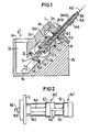
- the horizontally designed metering cylinder of the metering pump (not shown in more detail in FIG. 1) is flanged to the rear of the pump head Pk, the measuring chamber of the metering cylinder defined by the stroke of the metering piston Dk opening into the working chamber Ar. Furthermore, in the sectional view of FIG. 1, in the area between the seat SA and the cover D, the initial area of an outlet channel Ak can still be seen, to the rear end of which a horizontal discharge line (not shown in the drawing) for the medium M to be metered is connected.
- the inlet valve Ev is designed as a poppet valve which is inevitably controllable from the outside, the valve disk of which is designated VtE and the valve stem of which is designated VsE.
- the valve plate VtE On the side facing the ground seat SE, the valve plate VtE has an annular seal RdE embedded in a groove (not specified).
- the ring seal RdE is not made of an elastomer, but of a hard material - such as.
- the outlet valve Av is also designed as a poppet valve which is inevitably controllable from the outside, the valve disk of which is designated VtA and the valve stem of which is designated VsA.
- the valve plate VtA On the side facing the ground seat SA, the valve plate VtA carries an annular seal RdA which is embedded in a groove (not specified in any more detail) and which, in view of undesired volume changes in the hydraulic system, is in turn made of a hard material - such as B. polytetrafluoroethylene with carbon as a filler - is.
- a hollow cylindrical guide member Fg is also formed on the underside of the valve plate VtA, the task of which is explained in more detail below in connection with the valve guide.
- the valve stem VsE is first guided in the guide member Fg and then with a reduced-diameter area leading to the outside in the hollow-bore valve stem VsA of the exhaust valve Av.
- valve stem VsE which is of different diameters, enables the areas of the valve stems VsE and Vsl ⁇ to be flushed with the medium M to be metered. are of the same size in the outside diameter, so that volume changes in the hydraulic system are completely avoided when the exhaust valve Av moves.
- the valve guide of the exhaust valve Av which can also consist of a stainless steel, takes place via the valve stem VsA in a guide bore of the cover D, not specified.
- the inlet valve Ev and the outlet valve Av can inevitably be controlled from the outside via the associated valve stems VsE or VsA, the corresponding valve strokes being indicated by double arrows VhE or VhA.
- the working area Ar must be very well sealed to the outside.
- a sealing ring Drl enclosing the valve stem VsE is inserted into the guide member Fg, while a sealing ring Dr2 enclosing the valve stem VsA is inserted into the cover D.
- sealing rings Dr1 and Dr2 for example, adjustable angle ring packs are used.
- a bellows made of polytetrafluoroethylene or metal could also be used instead of the sealing ring Dr1.
- a liquid sealing medium This sealing medium, indicated by an arrow Dm, is introduced through a first sealant channel Dmk1 into the bearing gap between the cover D and the valve stem VsA.
- a second sealant channel Dmk2 which is introduced into the valve stem VsE as a longitudinal groove, is either filled with sealant Dm during assembly, or the sealant Dm is applied to it via the first sealant channel Dmk1 and a radial bore in the valve stem VsA.
- Pure resin for example, is used as the sealant Dm, which is also intended to act as a lubricant, if the medium M to be metered is a resin component.
- Castor oil is also suitable as a sealant Dm for the dosing of liquid components of epoxy resin compounds, since if there are any minor leaks, the castor oil is easily incorporated into the epoxy resin.
- the valves are actuated pneumatically or hydraulically via double-acting working cylinders Az1 and Az2, the piston K1 of the first working cylinder Az1 being fastened to the valve stem VsE of the inlet valve Ev (see FIG. 1) and the piston K2 of the second working cylinder Az2 is fastened on the valve stem VsA of the exhaust valve Av (see FIG. 1).
- the working cylinder Az1 via spacer Dh1 with the second working cylinder Az2 is connected and that the second working cylinder Az2 is in turn attached to the cover D via spacers Dh2.
Landscapes
- Engineering & Computer Science (AREA)
- General Engineering & Computer Science (AREA)
- Mechanical Engineering (AREA)
- Robotics (AREA)
- Details Of Reciprocating Pumps (AREA)
- Medicines Containing Plant Substances (AREA)
- Reciprocating Pumps (AREA)
- Electromagnetic Pumps, Or The Like (AREA)
Description
- Die Erfindung betrifft eine Dosierpumpe, insbesondere zum Dosieren flüssiger Bestandteile von Reaktionsharzmassen, nach dem Oberbegriff des Patentanspruchs 1.
- Reaktionsharzmassen werden durch Mischen von genau vorgegebenen Mengen Harz und Härter hergestellt, wobei in vielen Fällen auch mehrere Harze und mehrere Härter verwendet werden. Ausserdem können auf die Harz- und die Härterkomponenten auch Zusatzstoffe wie Füllstoffe, Farbstoffe, Haftvermittler, Beschleuniger und dgl. verteilt werden. Moderne Aufbereitungsanlagen für derartige Reaktionsharzmassen bestehen aus mindestens zwei Vorratsbehältern für die flüssigen Bestandteile bzw. Vorgemische, den Vorratsbehältern nachgeordneten Dosiereinrichtungen und einer Mischeinheit, wobei als Mischeinheit statische oder dynamische Durchlaufmischer oder auch grössre Mischbehälter verwendet werden. Als Dosiereinrichtungen werden für füllstoffhaltige Komponenten insbesondere oszillierende Verdrängerpumpen - wie z. B. Kolbenpumpen, Membranpumpen oder Balgpumpen - eingesetzt, wogegen für ungefülite Komponenten auch rotierende Verdrängerpumpen -wie z. B. Zahnradpumpen - eingesetzt werden können. Bei den insbesondere für das Dosieren füllstoffhaltiger Komponenten verwendeten Dosierpumpen mit hin- und herbewegbarem Verdränger sind sowohl ein Einlassventil als auch ein Auslassventil pro Verdränger erforderlich. Dabei werden üblicherweise selbsttätige Ventile - wie z. B. federbelastete Kugel-, Teller- oder Kegelventile - eingesetzt, die jedoch nur aufgrund der durch die Bewegung des Verdrängers erzeugten Druckunterschiede im Fördermedium betätigt werden (DE-OS-2851188). Dies bedeutet, dass z. B. aus einem unter Unterdruck stehenden Vorratsbehälter nur durch Erhöhung des hydrostatischen Druckes oder durch Druckerhöhung im Fördermedium mittels einer Vorpumpe zuverlässig gefördert werden kann. Vielfach ist es aber notwendig, die Komponente aus einem Vakuum zu dosieren. So müssen beispielsweise bei dem Verguss von elektrischen Hochspannungsbauteilen die Komponenten einer Epoxidgiessharzmasse aus einem Vakuum von beispielsweise 0,5 bis 100 mbar dosiert werden. Ausserdem besteht bei Dosierpumpen mit selbsttätigen federbelasteten Ventilen die Gefahr, dass körnige oder faserige Verunreinigungen zwischen Ventilsitz und beweglichem Ventilteil festgehalten werden. Dies führt dann aber zu einer vorübergehenden oder dauerhaften Funktionsstörung der Dosierpumpe, da das entsprechende Ventil durch die festgeklemmte Verunreinigung offengehalten wird und nur teilweise oder gar nicht gefördert wird.
- Es sind auch bereits als Kolbenpumpen ausgebildete Dosierpumpen bekannt, bei welchen ein als Drehschieber ausgebildetes gemeinsames Ein-und Auslassventil im Pumpenkopf angeordnet ist. Je nach Stellung dieses von aussen zwangsläufig steuerbaren Drehschiebers wird dann der Arbeitsraum im Pumpenkopf entweder mit einem Vorratsbehälter oder mit einem Ausflussrohr verbunden (Lueger Lexikon der Technik, Band 8, 1967, Deutsche Verlags-Anstalt Stuttgart, Seiten 2 und 3). Durch einen derartigen Drehschieber wird eine sehr genaue Dosierung ermöglicht, da während der Öffnungs- und Schliessvorgänge keine Änderungen des Volumens im hydraulischen System erfolgen. Andererseits unterliegt der Drehschieber insbesondere dann einem sehr hohen Verschleiss, wenn flüssige Bestandteile von Reaktionsharzmassen dosiert werden sollen, die abrasive Füllstoffe enthalten. Als Folge dieses Verschleisses treten dann Undichtigkeiten auf, durch welche ein Dosieren von Komponenten aus einem Vakuum von vorneherein ausgeschlossen werden muss.
- Aus der FR-A-2310479 ist eine gattungsgemässe Dosierpumpe bekannt, bei welcher das Einlassventil und das Auslassventil auf einem gemeinsamen Ventilschaft angeordnet sind und über einen an diesen Ventilschaft angelenkten Servoantrieb geregelt werden können. Der gemeinsame Ventilschaft erstreckt sich hierbei zwischen Einlassventil und Auslassventil durch den gesamten Pumpenkopf.
- Aus der GB-A-932031 ist eine Pumpe bekannt, bei welcher das Einlassventil und das Auslassventil auf gegenüberliegenden Seiten des Pumpenkopfes angeordnet sind, während ihre fluchtend ausgerichteten Ventilschäfte mit hydraulischen Betätigungszylindern gekoppelt sind. Die hydraulischen Betätigungszylinder sind dabei hydraulisch derart miteinander gekoppelt, dass beim Schliessen des Einlassventils das Auslassventil zwangsläufig geöffnet wird und ebenso bei Schliessen des Auslassventils das Einlassventil zwangsläufig geöffnet wird.
- Der Erfindung liegt die Aufgabe zugrunde, eine für das Dosieren flüssiger Bestandteile von Reaktionsharzmassen geeignete Dosierpumpe mit zwangsläufig von aussen steuerbaren Ventilen zu schaffen, bei welcher die Ventile keinem nennenswerten Verschleiss unterliegen und ein Dosieren der flüssigen Bestandteile aus einem Vakuum in ein Vakuum ermöglicht wird.
- Diese Aufgabe wird bei einer gattungsgemässen Dosierpumpe durch die kennzeichnenden Merkmale des Anspruchs 1 gelöst.
- Der Erfindung liegt die Erkenntnis zugrunde, dass von aussen zwangsläufig steuerbare Tellerventile mit koaxial im Pumpenkopf und teleskopisch ineinander gelagerten Ventilschäften zumindest weitgehend verschleissfrei arbeiten können und ausserdem eine zuverlässige Abdichtung nach aussen ermöglichen. Eine zwischen Tellerventil und Ventilsitz festgeklemmte Verunreinigung führt allenfalls zu einer äusserst kurzfristigen Störung, da sie durch die zwangsläufige Steuerung des Tellerventils entweder beim Schliesshub abgequetscht oder nach dem nächsten Öffnungshub vom Fördermedium mitgerissen wird. Neben der guten Abdichtung nach aussen ermöglicht die koaxiale und teleskopische Anordnung der Tellerventile auch noch eine äusserst kompakte Ventilpaarung ohne nennenswerte Änderungen des Volumens im hydraulischen System bei den Öffnungs- und Schliessvorgängen. Ein weiterer Vorteil der von aussen zwangsläufig steuerbaren Tellerventile besteht darin, dass der Öffnungshub so bemessen werden kann, dass der Spaltquerschnitt etwa dem übrigen Rohrquerschnitt entspricht und kein zusätzlicher Druckverlust in dem strömenden Medium durch den Ventilspalt entsteht. Aufgrund der zwangsläufigen Steuerung der Tellerventile können dann auch die Schliesskräfte individuell auf die jeweiligen Erfordernisse eingestellt werden. Weiterhin ist es auch möglich, die Einlassventile oder die Auslassventile von zwei oder mehreren Dosierpumpen über gemeinsame Steuerleitungen synchron anzusteuern, ohne dass sich durch unterschiedliche Viskosität der zu dosierenden Medien eine wesentliche Beeinflussung der Öffnungs- und Schliesszeiten ergibt. So lassen sich Dosieraggregate mit zwei oder mehreren Dosierpumpen problemlos realisieren. Schliesslich kann auch noch durch Offenhalten des Einlassventils und durch Bewegen des Verdrängers das entsprechende Medium zwischen einem Vorratsbehälter und dem Verdränger hin-und herbewegt werden, wodurch ein Entmischen oder Sedimentieren von Mischungsbestandteilen sicher verhindert werden kann.
- Gemäss einer bevorzugten Ausgestaltung der Erfindung ist der Ventilschaft des Einlassventils in dem Ventilteller und dem Ventilschaft des Auslassventils teleskopisch gelagert. Eine derartige auf die Strömungsverhältnisse im Arbeitsraum abgestimmte Anordnung der Ventilpaarung ermöglicht eine äusserst sichere Lagerung und Ventilführung von Einlassventil und Auslassventil im Ventilkopf. Ausserdem kann dann die Ventilführung des Einlassventils dadurch noch weiter verbessert werden, dass an den Ventilteller des Auslassventils ein zusätzliches Führungsglied für den Ventilschaft des Einlassventils angebracht wird.
- Vorzugsweise ist der Ventilschaft des Auslassventils in einem an den Pumpenkopf angeflanschten Deckel gelagert. Hierdurch werden Wartungsarbeiten an der Dosierpumpe erheblich erleichtert, da die aus Einlassventil und Auslassventil bestehende Ventilanordnung ohne Auftrennen der das zu dosierende Medium führenden Rohrleitung durch einfaches Lösen des Deckels demontiert werden kann.
- Gemäss einer besonders bevorzugten weiteren Ausgestaltung der Erfindung ist vorgesehen, dass die Aussendurchmesser der Ventilschäfte von Einlassventil und Auslassventil zumindest in den von dem zu dosierenden Medium umspülten Bereichen gleich gross sind. Durch diese Massnahme können Volumenänderungen bei einer Bewegung des Auslassventils vollständig vermieden werden, d. h. zwei oder mehrere Dosierströme bleiben dann im Volumenverhältnis stets unverändert.
- Für ein schnelles Ausfördern von Luftblasen aus dem Arbeitsraum hat es sich als zweckmässig herausgestellt, wenn die aus Einlassventil und Auslassventil bestehende Ventilanordnung senkrecht hängend bis waagrecht liegend in den Pumpenkopf eingebaut wird. Besonders günstig ist es jedoch, wenn die aus Einlassventil und Auslassventil bestehende Ventilanordnung unter einem Neigungswinkel von etwa 45° in den Pumpenkopf eingebaut wird. In diesem Fall kann dann eine Sedimentation in der das zu dosierende Medium führenden Zuleitung beispielsweise durch die Anordnung eines Rührers oder dgl. besonders leicht vermieden werden.
- Zum schnellen, restlosen Ausfördern von Luftblasen aus dem Arbeitsraum und somit auch zum einfachen Anfahren der Dosierpumpe ist es ferner besonders günstig, wenn das Einlassventil im unteren Bereich und das Auslassventil im oberen Bereich des Arbeitsraumes im Pumpenkopf angeordnet sind. Bei einer derartigen Anordnung der Ventile stimmt dann die Richtung aufsteigender Luftblasen mit der Förderrichtung des zu dosierenden Mediums überein.
- Im Hinblick auf die nach aussen vakuumdichte Ausgestaltung der Dosierpumpe ist es auch zweckmässig, wenn in das Auslassventil ein den Ventilschaft des Einlassventils umschliessender Dichtring eingesetzt ist. In entsprechender Weise kann dann auch in den Deckel ein den Ventilschaft des Auslassventils umschliessender Dichtring eingesetzt werden. Eine weitere Verbesserung der Voraussetzungen für das Fördern bzw. Dosieren von Medien aus unter Vakuum oder unter Druck stehenden Vorratsbehältern kann dann schliesslich dadurch erreicht werden, dass in die Lagerspalte zwischen Deckel und Ventilschaft des Auslassventils und zwischen Ventilschaft des Auslassventils und Ventilschaft des Einlassventils ein flüssiges Dichtmedium einleitbar ist.
- Sind das Einlassventil und das Auslassventil von aussen über hintereinander angeordnete doppeltwirkende Arbeitszylinder pneumatisch oder hydraulisch betätigbar, so ergibt sich eine besonders kompakte und raumsparende Ausgestaltung des gesamten Dosierpumpenaggregates.
- Ein Ausführungsbeispiel der Erfindung ist in der Zeichnung dargestellt und wird im folgenden näher beschrieben. Es zeigen:
- Fig. 1 einen Schnitt durch den Pumpenkopf einer Dosierpumpe zum Dosieren flüssiger Bestandteile von Reaktionsharzmassen und
- Fig. 2 eine Tandem-Anordnung zweier Arbeitszylinder für die Betätigung der in dem Pumpenkopf nach Fig. 1 angeordneten Ventile.
- Fig. 1 zeigt einen Schnitt durch den beispielsweise aus einem nicht-rostenden Stahl bestehenden Pumpenkopf Pk einer als Kolbenpumpe ausgebildeten Dosierpumpe. In den blockförmig ausgebildeten Pumpenkopf Pk ist von oben her in vertikaler Richtung ein Einlasskanal Ek eingebracht, an dessen oberes Anschlussende Ae eine in der Zeichnung nicht dargestellte vertikale Zufuhrleitung für das durch einen Pfeil M angedeutete zu dosierende Medium angeschlossen wird. Vom Bodenbereich des Einlasskanals Ek ausgehend zweigt ein unter einem Neigungswinkel zur Horizontalen von β = 45° schräg nach oben führender zweiter Kanal ab, welcher den mit Ar bezeichneten Arbeitsraum der Dosierpumpe bildet und an seinem oberen Ende durch einen von aussen angeflanschten Deckel D verschlossen ist. Ausserdem ist dieser zweite Kanal in seinem Durchmesser so abgestuft, dass von unten ausgesehen zunächst ein Sitz SE für ein insgesamt mit Ev bezeichnetes Einlassventil und im Abstand danach ein Sitz SA für ein insgesamt mit Av bezeichnetes Auslassventil gebildet wird.
- Im Bereich zwischen den Sitzen SE und SA ist der waagrecht ausgebildete und in Fig. 1 nicht näher dargestellte Dosierzylinder der Dosierpumpe an die Rückseite des Pumpenkopfes Pk angeflanscht, wobei der durch den Hub des Dosierkolbens Dk definierte Messraum des Dosierzylinders in den Arbeitsraum Ar einmündet. Ferner ist in dem Schnittbild der Fig. 1 im Bereich zwischen dem Sitz SA und dem Deckel D noch der Anfangsbereich eines Auslasskanals Ak zu erkennen, an dessen rückwärtiges Ende eine in der Zeichnung nicht dargestellte horizontale Abfuhrleitung für das zu dosierende Medium M angeschlossen wird.
- Das Einlassventil Ev ist als ein von aussen zwangsläufig steuerbares Tellerventil ausgebildet, dessen Ventilteller mit VtE und dessen Ventilschaft mit VsE bezeichnet sind. Auf der dem geschliffenen Sitz SE zugewandten Seite trägt der Ventilteller VtE eine in eine nicht näher bezeichnete Nut eingelassene Ringdichtung RdE. Um auch kleinste Änderungen im Volumen des hydraulischen Systems der Dosierpumpe zu vermeiden, besteht die Ringdichtung RdE nicht aus einem Elastomer, sondern aus einem harten Werkstoff - wie z. B. Polytetrafluoräthylen mit Kohle als Füllstoff.
- Das Auslassventil Av ist ebenfalls als ein von aussen zwangsläufig steuerbares Tellerventil ausgebildet, dessen Ventilteller mit VtA und dessen Ventilschaft mit VsA bezeichnet sind. Auf der dem geschliffenen Sitz SA zugewandten Seite trägt der Ventilteller VtA eine in eine nicht näher bezeichnete Nut eingelassene Ringdichtung RdA, die im Hinblick auf unerwünschte Volumenänderungen im hydraulischen System wiederum aus einem harten Werkstoff - wie z. B. Polytetrafluoräthylen mit Kohle als Füllstoff - besteht. An die Unterseite des Ventiltellers VtA ist ferner noch ein hohlzylindrisches Führungsglied Fg angeformt, dessen Aufgabe nachfolgend im Zusammenhang mit der Ventilführung näher erläutert wird.
- Die Ventilführung des beispielsweise aus einem nicht-rostenden Stahl bestehenden Einlassventils Ev erfolgt dadurch, dass sein Ventilschaft VsE das gesamte Auslassventil Av koaxial durchsetzt, d. h. das Einlassventil Ev und das Auslassventil Av besitzen eine gemeinsame Ventilachse Va, die unter dem bereits erwähnten Neigungswinkel von β = 45° zur Horizontalen ausgerichtet ist. Dabei ist der Ventilschaft VsE zunächst in dem Führungsglied Fg und dann mit einem im Durchmesser verringerten, nach aussen führenden Bereich in dem hohlgebohrten Ventilschaft VsA des Auslassventils Av geführt. Durch diese im Durchmesser verschiedene Ausgestaltung des Ventilschaftes VsE können dann die von dem zu dosierenden Medium M umspülten Bereiche der Ventilschäfte VsE und Vsl}. im Aussendurchmesser gleich gross ausgebildet werden, so dass Volumenänderungen im hydraulischen System bei einer Bewegung des Auslassventils Av vollständig vermieden werden. Die Ventilführung des Auslassventils Av, welches ebenfalls aus einem nicht-rostenden Stahl bestehen kann, erfolgt über den Ventilschaft VsA in einer nicht näher bezeichneten Führungsbohrung des Deckels D.
- Durch die vorstehend beschriebenen Ventilführungen können das Einlassventil Ev und das Auslassventil Av von aussen über die zugehörigen Ventilschäfte VsE bzw. VsA zwangsläufig gesteuert werden, wobei die entsprechenden Ventilhübe durch Doppelpfeile VhE bzw. VhA angedeutet sind.
- Damit die Dosierpumpe flüssige Bestandteile von Reaktionsharzmassen, wie z. B. eine Harzkomponente oder eine Härterkomponente, aus einem Vakuum in ein Vakuum fördern kann, muss der Arbeitsraum Ar nach aussen sehr gut abgedichtet werden. Hierzu ist in das Führungsglied Fg ein den Ventilschaft VsE umschliessender Dichtring Drl eingesetzt, während in den Deckel D ein den Ventilschaft VsA umschliessender Dichtring Dr2 eingesetzt ist. Als Dichtringe Dr1 und Dr2 werden beispielsweise im Druck einstellbare Winkelringpackungen verwendet. Zum Abdichten des Ventilschaftes VsE könnte anstelle des Dichtringes Dr1 aber auch ein Federbalg aus Polytetrafluoräthylen oder Metall verwendet werden. Eine zusätzliche Abdichtung der Ventilschäfte VsE und VsA gegen die Atmosphäre beim Vakuum-Betrieb wird durch ein flüssiges Dichtmedium ermöglicht. Dieses durch einen Pfeil Dm angedeutete Dichtmedium wird durch einen ersten Dichtmittelkanal Dmk1 in den Lagerspalt zwischen dem Deckel D und dem Ventilschaft VsA eingeleitet. Ein zweiter als Längsnut in den Ventilschaft VsE eingebrachter Dichtmittelkanal Dmk2 wird entweder bei der Montage mit Dichtmittel Dm gefüllt oder aber über den ersten Dichtmittelkanal Dmk1 und eine Radialbohrung im Ventilschaft VsA mit dem Dichtmittel Dm beaufschlagt. Als Dichtmittel Dm, das gleichzeitig auch als Schmiermittel wirken soll, wird beispielsweise reines Harz verwendet, wenn es sich bei dem zu dosierenden Medium M um eine Harzkomponente handelt. Für das Dosieren flüssiger Bestandteile von Epoxidharzmassen ist auch Rizinusöl als Dichtmittel Dm geeignet, da bei eventuell auftretenden geringfügigen Leckagen das Rizinusöl problemlos in das Epoxidharz eingebaut wird.
- Gemäss Fig. 2 erfolgt die Betätigung der Ventile pneumatisch oder hydraulisch über hintereinander angeordnete doppeltwirkende Arbeitszylinder Az1 und Az2, wobei der Kolben K1 des ersten Arbeitszylinders Az1 auf dem Ventilschaft VsE des Einlassventils Ev (vgl. Fig. 1) befestigt ist und wobei der Kolben K2 des zweiten Arbeitszylinders Az2 auf dem Ventilschaft VsA des Auslassventils Av (vgl. Fig. 1) befestigt ist. Aus der stark vereinfachten schematischen Darstellung ist ferner ersichtlich, dass der Arbeitszylinder Az1 über Distanzhalter Dh1 mit dem zweiten Arbeitszylinder Az2 verbunden ist und dass der zweite Arbeitszylinder Az2 seinerseits über Distanzhalter Dh2 am Deckel D befestigt ist.
Claims (12)
Priority Applications (1)
| Application Number | Priority Date | Filing Date | Title |
|---|---|---|---|
| AT86101687T ATE39167T1 (de) | 1985-02-14 | 1986-02-10 | Dosierpumpe. |
Applications Claiming Priority (2)
| Application Number | Priority Date | Filing Date | Title |
|---|---|---|---|
| DE3505108 | 1985-02-14 | ||
| DE3505108 | 1985-02-14 |
Publications (2)
| Publication Number | Publication Date |
|---|---|
| EP0193752A1 EP0193752A1 (de) | 1986-09-10 |
| EP0193752B1 true EP0193752B1 (de) | 1988-12-07 |
Family
ID=6262539
Family Applications (1)
| Application Number | Title | Priority Date | Filing Date |
|---|---|---|---|
| EP86101687A Expired EP0193752B1 (de) | 1985-02-14 | 1986-02-10 | Dosierpumpe |
Country Status (5)
| Country | Link |
|---|---|
| US (1) | US4715795A (de) |
| EP (1) | EP0193752B1 (de) |
| JP (1) | JPS62282181A (de) |
| AT (1) | ATE39167T1 (de) |
| DE (1) | DE3661375D1 (de) |
Families Citing this family (11)
| Publication number | Priority date | Publication date | Assignee | Title |
|---|---|---|---|---|
| US5061156A (en) * | 1990-05-18 | 1991-10-29 | Tritec Industries, Inc. | Bellows-type dispensing pump |
| JP3433397B2 (ja) * | 1992-09-23 | 2003-08-04 | フィッシャー アンド ペイケル アプライアンシーズ リミテッド | フロート弁装置及び呼吸用加湿器 |
| US5232023A (en) * | 1992-12-22 | 1993-08-03 | Tri-Clover, Inc. | Manifold valve assemblies |
| WO2000067978A1 (en) * | 1999-05-07 | 2000-11-16 | Csir | Method of and apparatus for charging plasticized polymeric moulding material into a mould |
| KR100796425B1 (ko) | 2005-08-23 | 2008-01-21 | 도쿄 오카 고교 가부시키가이샤 | 도포장치 |
| JP3938388B2 (ja) * | 2005-08-23 | 2007-06-27 | 東京応化工業株式会社 | 塗布装置 |
| JP2007083237A (ja) * | 2006-12-01 | 2007-04-05 | Tokyo Ohka Kogyo Co Ltd | 塗布装置 |
| JP5041827B2 (ja) * | 2007-02-23 | 2012-10-03 | 東京応化工業株式会社 | 塗布装置 |
| ES2716964T3 (es) | 2014-10-13 | 2019-06-18 | Alfa Srl | Bomba volumétrica y grupo de bombeo para productos fluidos y método de uso de los mismos |
| CN110259655A (zh) * | 2019-07-30 | 2019-09-20 | 淮安市威力泵业科技有限公司 | 一种自带安全阀的柱塞式计量泵 |
| CA3223041A1 (en) * | 2021-06-11 | 2022-12-15 | Gea Tuchenhagen Gmbh | Double seat valve |
Family Cites Families (12)
| Publication number | Priority date | Publication date | Assignee | Title |
|---|---|---|---|---|
| CA581543A (en) * | 1959-08-18 | Drabik Josef | Pipe connection for two or more series-connected apparatuses | |
| US979024A (en) * | 1909-02-25 | 1910-12-20 | Thomas L Moore | Valve mechanism for explosive-engines. |
| FR545071A (fr) * | 1921-12-24 | 1922-10-05 | Gnome Et Rhone Moteurs | Culasse avec disposition perfectionnée des soupapes pour moteurs à combustion interne |
| US2367893A (en) * | 1943-05-08 | 1945-01-23 | Sheen Milton Roy | Liquid pump |
| FR1009802A (fr) * | 1948-06-25 | 1952-06-04 | Perfectionnements apportés aux soupapes d'admission pour des moteurs à combustion interne | |
| FR1233564A (fr) * | 1959-03-31 | 1960-10-12 | Procédé et dispositif de liaison hydraulique des clapets d'une pompe à piston | |
| DE1163622B (de) * | 1960-12-24 | 1964-02-20 | Linde S Eismaschinen Ag Zweign | Umschaltventil fuer Tieftemperatur-Regeneratoren |
| JPS5235538Y2 (de) * | 1973-07-12 | 1977-08-13 | ||
| DE2520402C3 (de) * | 1975-05-07 | 1978-12-07 | Jagenberg-Werke Ag, 4000 Duesseldorf | Dosiervorrichtung für Flüssigkeiten |
| US4211345A (en) * | 1977-03-30 | 1980-07-08 | Krauss-Maffei Aktiengesellschaft | Apparatus for the feeding (metering) of liquid synthetic-resin components |
| DE2851188A1 (de) * | 1978-11-27 | 1980-06-04 | Siemens Ag | Ventilvorrichtung fuer oszillierende verdraengerpumpen, insbesondere dosierpumpen |
| DE3174609D1 (en) * | 1981-03-24 | 1986-06-19 | Holstein & Kappert Gmbh | Double-seat valve with leak control |
-
1986
- 1986-01-31 US US06/825,143 patent/US4715795A/en not_active Expired - Fee Related
- 1986-02-10 DE DE8686101687T patent/DE3661375D1/de not_active Expired
- 1986-02-10 AT AT86101687T patent/ATE39167T1/de not_active IP Right Cessation
- 1986-02-10 EP EP86101687A patent/EP0193752B1/de not_active Expired
- 1986-02-12 JP JP61028738A patent/JPS62282181A/ja active Pending
Also Published As
| Publication number | Publication date |
|---|---|
| DE3661375D1 (en) | 1989-01-12 |
| EP0193752A1 (de) | 1986-09-10 |
| JPS62282181A (ja) | 1987-12-08 |
| US4715795A (en) | 1987-12-29 |
| ATE39167T1 (de) | 1988-12-15 |
Similar Documents
| Publication | Publication Date | Title |
|---|---|---|
| EP0507127B1 (de) | Rohrweiche | |
| EP0193752A1 (de) | Dosierpumpe | |
| DE3341643A1 (de) | Vorgesteuertes druckentlastungs- und steuerventil | |
| DE2027395A1 (de) | Doppelt wirkender druckmittelbeaufschlagter Arbeitszylinder mit Endlagendämpfung | |
| DE8504155U1 (de) | Dosierpumpe | |
| DE2113602A1 (de) | Absperrorgan mit druckentlastetem Verschlussorgan | |
| EP0176528B1 (de) | Drosselorgan zur herabsetzung des drucks in förderleitungen | |
| DE2825144C2 (de) | Mehrzylinderdickstoffpumpe | |
| DE2235188B2 (de) | Verstellhülse für die Leitschaufeln eines Axialverdichters | |
| DE3342945A1 (de) | Absperrvorrichtung fuer einen stroemungskanal | |
| DE3117027C2 (de) | ||
| DE903159C (de) | Ventil mit Spindelabdichtung durch ein die Spindel umschliessendes Schlauchstueck | |
| DE3049473C2 (de) | ||
| DE3030599A1 (de) | Zylinder und mit kolben/zylinder-baugruppen mit regelbarem hub | |
| DE2531019A1 (de) | Zweifach-ventil mit kontrolloeffnung | |
| DE3227235C2 (de) | ||
| EP0089568A1 (de) | Druckmittelbetätigte Drehantriebs-Stellvorrichtung | |
| DE69107234T2 (de) | Mittel zur Erzeugung eines Vorspanndruckes für Wellendichtungen. | |
| DE2039339C3 (de) | 4/2-Wegeventil für die Umsteuerung der Druckwasserströme zum Betrieb der Motorzylinder einer Betonpumpe | |
| DE2127181B2 (de) | Druckmittelantrieb fuer absperrschieber oder dgl. mit einem haupt- und einem hilfskolben | |
| DE2334940C3 (de) | Spannzylinder | |
| DE1272658B (de) | Armatur fuer Mehrwegsteuerung | |
| EP0839961A1 (de) | Absperrvorrichtung für Verkehrsflächen | |
| CH564694A5 (en) | Pneumatic piston and cylinder combination - uses double acting hollow piston on central slide to pump hydraulic fluid | |
| DE19820102A1 (de) | Oszillier-Zylinder |
Legal Events
| Date | Code | Title | Description |
|---|---|---|---|
| PUAI | Public reference made under article 153(3) epc to a published international application that has entered the european phase |
Free format text: ORIGINAL CODE: 0009012 |
|
| AK | Designated contracting states |
Kind code of ref document: A1 Designated state(s): AT CH DE FR GB IT LI NL |
|
| 17P | Request for examination filed |
Effective date: 19860923 |
|
| 17Q | First examination report despatched |
Effective date: 19871201 |
|
| GRAA | (expected) grant |
Free format text: ORIGINAL CODE: 0009210 |
|
| AK | Designated contracting states |
Kind code of ref document: B1 Designated state(s): AT CH DE FR GB IT LI NL |
|
| REF | Corresponds to: |
Ref document number: 39167 Country of ref document: AT Date of ref document: 19881215 Kind code of ref document: T |
|
| REF | Corresponds to: |
Ref document number: 3661375 Country of ref document: DE Date of ref document: 19890112 |
|
| ET | Fr: translation filed | ||
| PGFP | Annual fee paid to national office [announced via postgrant information from national office to epo] |
Ref country code: AT Payment date: 19890127 Year of fee payment: 4 |
|
| PGFP | Annual fee paid to national office [announced via postgrant information from national office to epo] |
Ref country code: FR Payment date: 19890222 Year of fee payment: 4 |
|
| PGFP | Annual fee paid to national office [announced via postgrant information from national office to epo] |
Ref country code: NL Payment date: 19890228 Year of fee payment: 4 |
|
| ITF | It: translation for a ep patent filed | ||
| GBT | Gb: translation of ep patent filed (gb section 77(6)(a)/1977) | ||
| PGFP | Annual fee paid to national office [announced via postgrant information from national office to epo] |
Ref country code: CH Payment date: 19890524 Year of fee payment: 4 |
|
| PLBE | No opposition filed within time limit |
Free format text: ORIGINAL CODE: 0009261 |
|
| STAA | Information on the status of an ep patent application or granted ep patent |
Free format text: STATUS: NO OPPOSITION FILED WITHIN TIME LIMIT |
|
| 26N | No opposition filed | ||
| PG25 | Lapsed in a contracting state [announced via postgrant information from national office to epo] |
Ref country code: GB Effective date: 19900210 Ref country code: AT Effective date: 19900210 |
|
| ITTA | It: last paid annual fee | ||
| PG25 | Lapsed in a contracting state [announced via postgrant information from national office to epo] |
Ref country code: LI Effective date: 19900228 Ref country code: CH Effective date: 19900228 |
|
| PG25 | Lapsed in a contracting state [announced via postgrant information from national office to epo] |
Ref country code: NL Effective date: 19900901 |
|
| GBPC | Gb: european patent ceased through non-payment of renewal fee | ||
| NLV4 | Nl: lapsed or anulled due to non-payment of the annual fee | ||
| PG25 | Lapsed in a contracting state [announced via postgrant information from national office to epo] |
Ref country code: FR Effective date: 19901031 |
|
| REG | Reference to a national code |
Ref country code: CH Ref legal event code: PL |
|
| REG | Reference to a national code |
Ref country code: FR Ref legal event code: ST |
|
| PGFP | Annual fee paid to national office [announced via postgrant information from national office to epo] |
Ref country code: DE Payment date: 19920901 Year of fee payment: 7 |
|
| PG25 | Lapsed in a contracting state [announced via postgrant information from national office to epo] |
Ref country code: DE Effective date: 19931103 |
|
| PG25 | Lapsed in a contracting state [announced via postgrant information from national office to epo] |
Ref country code: IT Free format text: LAPSE BECAUSE OF NON-PAYMENT OF DUE FEES;WARNING: LAPSES OF ITALIAN PATENTS WITH EFFECTIVE DATE BEFORE 2007 MAY HAVE OCCURRED AT ANY TIME BEFORE 2007. THE CORRECT EFFECTIVE DATE MAY BE DIFFERENT FROM THE ONE RECORDED. Effective date: 20050210 |