EP0193463A2 - Device including a robot manipulator for supplying a machine tool with work pieces and removing them from it - Google Patents
Device including a robot manipulator for supplying a machine tool with work pieces and removing them from it Download PDFInfo
- Publication number
- EP0193463A2 EP0193463A2 EP86400384A EP86400384A EP0193463A2 EP 0193463 A2 EP0193463 A2 EP 0193463A2 EP 86400384 A EP86400384 A EP 86400384A EP 86400384 A EP86400384 A EP 86400384A EP 0193463 A2 EP0193463 A2 EP 0193463A2
- Authority
- EP
- European Patent Office
- Prior art keywords
- carriage
- plates
- movable
- robot
- workpiece
- Prior art date
- Legal status (The legal status is an assumption and is not a legal conclusion. Google has not performed a legal analysis and makes no representation as to the accuracy of the status listed.)
- Withdrawn
Links
Images


Classifications
-
- B—PERFORMING OPERATIONS; TRANSPORTING
- B23—MACHINE TOOLS; METAL-WORKING NOT OTHERWISE PROVIDED FOR
- B23Q—DETAILS, COMPONENTS, OR ACCESSORIES FOR MACHINE TOOLS, e.g. ARRANGEMENTS FOR COPYING OR CONTROLLING; MACHINE TOOLS IN GENERAL CHARACTERISED BY THE CONSTRUCTION OF PARTICULAR DETAILS OR COMPONENTS; COMBINATIONS OR ASSOCIATIONS OF METAL-WORKING MACHINES, NOT DIRECTED TO A PARTICULAR RESULT
- B23Q7/00—Arrangements for handling work specially combined with or arranged in, or specially adapted for use in connection with, machine tools, e.g. for conveying, loading, positioning, discharging, sorting
- B23Q7/04—Arrangements for handling work specially combined with or arranged in, or specially adapted for use in connection with, machine tools, e.g. for conveying, loading, positioning, discharging, sorting by means of grippers
-
- B—PERFORMING OPERATIONS; TRANSPORTING
- B23—MACHINE TOOLS; METAL-WORKING NOT OTHERWISE PROVIDED FOR
- B23Q—DETAILS, COMPONENTS, OR ACCESSORIES FOR MACHINE TOOLS, e.g. ARRANGEMENTS FOR COPYING OR CONTROLLING; MACHINE TOOLS IN GENERAL CHARACTERISED BY THE CONSTRUCTION OF PARTICULAR DETAILS OR COMPONENTS; COMBINATIONS OR ASSOCIATIONS OF METAL-WORKING MACHINES, NOT DIRECTED TO A PARTICULAR RESULT
- B23Q7/00—Arrangements for handling work specially combined with or arranged in, or specially adapted for use in connection with, machine tools, e.g. for conveying, loading, positioning, discharging, sorting
- B23Q7/10—Arrangements for handling work specially combined with or arranged in, or specially adapted for use in connection with, machine tools, e.g. for conveying, loading, positioning, discharging, sorting by means of magazines
-
- B—PERFORMING OPERATIONS; TRANSPORTING
- B65—CONVEYING; PACKING; STORING; HANDLING THIN OR FILAMENTARY MATERIAL
- B65G—TRANSPORT OR STORAGE DEVICES, e.g. CONVEYORS FOR LOADING OR TIPPING, SHOP CONVEYOR SYSTEMS OR PNEUMATIC TUBE CONVEYORS
- B65G65/00—Loading or unloading
Definitions
- Device for loading and unloading parts on a machine tool comprising a manipulator robot.
- the invention relates to a manipulator robot for loading and unloading workpieces, in particular for machine tools such as a lathe or the like.
- manipulating robots allowing the loading and unloading of workpieces.
- the operations of the robots forming part of the prior art are broken down into a series of more or less numerous movements determining a loss of time and consequently very slow working rhythms resulting in lower productivity.
- the first operation consists of gripping the workpiece on a tray or a carousel and then bringing it next to the work tool.
- the second operation consists in taking back the machined part then replacing it in the housing of the tray or the carousel left vacant.
- a third operation then consists in evacuating the machined part.
- a final operation consists in repositioning the robot gripping members opposite a new blank.
- the object of the present invention is to remedy to these disadvantages and to create a manipulator robot allowing the simultaneous loading and unloading of raw parts and machined parts using simple movements or or much faster rates and increased productivity.
- the present invention also aims to create a robot manipulator of simple design and easy handling with great speed of execution while allowing the simultaneous processing of two parts one raw, the other machined.
- the invention relates to a manipulator robot for loading and unloading of workpieces in particular for machine tools such as lathe or the like, characterized in that it comprises a carriage movable in translation on a gantry under the action of a jack to bring a workpiece from a first plate to the work tool and simultaneously separate a workpiece on a second plate, the carriage being provided with two prong heads, the prongs of the one of the heads being open for gripping a workpiece presented on a tray while the claws of the other head are in the clamping position for discharging the workpiece on a tray, gripping a raw workpiece and unloading a the workpiece being carried out in a simultaneous movement, the robot also being associated with an automatic device for loading the plates, the various operations of a work cycle of the manipulator robot and the loading device being carried out from a programmable control unit.
- Such a manipulator robot saves an extremely large amount of time due to the simultaneous treatment of a raw part and a machined part.
- the carriage provided with the claw-carrying heads is movable in horizontal translation as well as in rotation around its guide axis for taking over a machined part and fitting a raw part.
- the claw-bearing heads are pivotable on the carriage.
- the plates, provided with raw parts and machined parts, arranged under the claw-carrying carriage, are placed on supports movable in vertical translation.
- the plates carried by the vertically movable supports are rotated at an angle determined at the end of each working cycle of the carriage.
- the plates are circular in shape and are provided at their periphery with pallet carriers allowing the accommodation of either the raw parts or the machined parts.
- the automatic loading device for the trays comprises a frame provided on each side with vertical columns, each column comprising an endless chain driven by a motor and on which are fixed support arms carrying the trays, a table movable in horizontal translation under the effect of a jack being disposed in the area between the two columns.
- the arms of one of the columns carrying the plates facing the movable table are driven in a downward movement while the arms facing the movable table of the other column are animated by an upward movement.
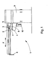
- FIG. 1 is a partial side view of the robot manipulator.
- the manipulator robot 1 allows the simultaneous loading and unloading of workpieces especially for machine tools such as lathes.
- the manipulator robot 1 comprises a mobile carriage 2.
- the mobile carriage 2 is mounted on a gantry 3.
- the mobile carriage 2 is movable in translation under the action of a jack. It allows a workpiece 4 to be brought from a first plate 5 to the working tool not shown in this figure and connected to a fastening device 6.
- This tool can be a cutter for example.
- the carriage makes it possible to deposit a machined part on a second plate not visible in this figure when it supports the raw part 4.
- the carriage 2 is provided with two claw-carrying heads 7.
- the carriage 2 is movable in horizontal translation but also in rotation about its guide axis. These two combined movements of translation and rotation of the carriage make it possible to simultaneously treat the blank and the workpiece.
- the plates serve as supports for the raw parts and the machined parts. These trays are arranged under the carriage 2 when it is in its position corresponding to the start of a work cycle as shown in this figure.
- the plates 5 are placed on supports 8 movable in vertical translation.
- the plates 5 are rotated at a determined angle at the end of each working cycle of the carriage 2 so as to be correctly positioned opposite the claw-bearing heads simultaneously treating the raw parts and the machined parts.
- the plates 5 are circular in shape and are provided at their periphery with pallet carriers allowing the accommodation of either the raw parts or the machined parts.
- the claw-bearing heads 7 are pivotally mounted on the carriage 2 which moves in translation along the arrow F.
- the various operations of a work cycle of the robot 1 are carried out from a programmable control unit 9.
- the work cycle of robot 1 is carried out as follows. First of all, the plates 5 are positioned in the axis of the carriage 2 of the gantry 3 and of the claw-carrying heads 7. The plates are moved vertically upwards using jacks 10. In this position, the claws of the first head are open to grip the blank 4. The claws of the head arranged on the other side of the carriage not shown in this figure are closed and enclose the machined part intended to be deposited on the corresponding plate.
- the claws of the head 7 enclose the blank to be machined. Simultaneously, the claws of the second head not shown in the figure are open and the workpiece is placed on the plate. This second head is therefore free to grasp a new machined part.
- the plates 5 are then lowered.
- the two heads 7 are rotated by 90 ° and the carriage 2 is launched in the direction of the machine tool.
- the gantry 3 is pivoted 90 °. After pivoting of the gantry, the carriage 2 traverses the introduction stroke by presenting the free head with its claws open. The claws are then closed to clamp the workpiece carried by the tool. The tool releases the workpiece and determines a slight backward movement of the carriage 2.
- the gantry carrying the carriage is pivoted by 180 ° so as to present the rough part facing the tool.
- the latter takes charge of the blank, which determines the opening of the claws of the released head and the recoil of the carriage 2.
- the gantry pivots 90 ° so that the free head can come opposite a new blank. to grasp when the carriage 2 has returned to its initial position. This determines the end of a work cycle.
- the loading device 11 comprises in particular a frame 12. The latter is provided on each of its sides with a vertical column 13.
- Each column 13 comprises an endless chain or any other similar device driven by a motor .
- Support arms 14 are attached to the endless chain. They carry circular plates 5.
- One of the columns 13 carries the plates provided with the raw parts while the other column carries the plates provided with the machined parts.
- a table 15 movable in horizontal translation under the effect of a jack 16 is disposed between the two columns 13.
- the arms 14 located opposite the table 15 of one of the columns 13 are moved downward while the arms 14 of the other column 13 are animated by an upward movement.
- This automatic loading device makes it possible to present the raw parts always at the same point with a single translational movement while simultaneously allowing to grasp a raw part and to remove the workpiece in one movement.
- the automatic loading device 11 is only shown partially.
- the two central plates 5 and the plate located at the extreme right of this drawing are arranged on the table 15 movable in translation under the effect of the jack 16.
- the plate 5, arranged at the extreme right of this figure comprises the machined parts intended to be transferred, while the plate 5, arranged on the far left of FIG. 5, comprises the raw parts intended to be supported by the table 15.
- the combined translation movements of the table 15 in translation horizontal and supports 8 in vertical translation allow in a single movement to obtain the release of the plate 5 carrying the machined parts and to present a new plate carrying the raw parts in the position suitable for their support by the claw-carrying head taking over the raw parts.
- the presentation of the raw parts is carried out on the plate along a single rotary axis determined by the support 8.
Abstract
Description
Dispositif de chargement et de déchargement des pièces sur une machine-outil comprenant un robot manipulateur.-Device for loading and unloading parts on a machine tool comprising a manipulator robot.
L'invention concerne un robot manipulateur pour le chargement et le déchargement de pièces à usiner notamment pour machines-outils telles que tour ou autre.The invention relates to a manipulator robot for loading and unloading workpieces, in particular for machine tools such as a lathe or the like.
On connalt déjà des robots manipulateurs permettant le chargement et le déchargement de pièces à usiner. Cependant, les opérations des robots faisant partie de l'art antérieur se décomposent en une série de mouvements plus ou moins nombreux déterminant une perte de temps et par conséquent des rythmes de travail très lents d'où une productivité moindre. En effet, dans le cas des robots manipulateurs connus, il est nécessaire, quel que soit le dispositif d'alimentation en pièce à usiner, de prévoir au moins deux opérations essentielles et distinctes. La première opération consiste à saisir la pièce à usiner sur un plateau ou un carrousel puis de l'amener en regard de l'outil de travail. La seconde opération consiste à reprendre la pièce usinée puis la replacer dans le logement du plateau ou du carrousel laissé vacant. Une troisième opération consiste ensuite à évacuer la pièce usinée. Enfin, une dernière opération consiste à repositionner les organes de prise du robot en regard d'une nouvelle pièce brute. Ces diverses manipulations supposent en conséquence un grand nombre de Mouvements occasionnant une perte de temps importante.We already know manipulating robots allowing the loading and unloading of workpieces. However, the operations of the robots forming part of the prior art are broken down into a series of more or less numerous movements determining a loss of time and consequently very slow working rhythms resulting in lower productivity. Indeed, in the case of known manipulator robots, it is necessary, whatever the workpiece feed device, to provide at least two essential and distinct operations. The first operation consists of gripping the workpiece on a tray or a carousel and then bringing it next to the work tool. The second operation consists in taking back the machined part then replacing it in the housing of the tray or the carousel left vacant. A third operation then consists in evacuating the machined part. Finally, a final operation consists in repositioning the robot gripping members opposite a new blank. These various manipulations therefore assume a large number of movements causing a significant loss of time.
La présente invention a pour but de remédier à ces inconvénients et de créer un robot manipulateur permettant le chargement et le déchargement simultanés de pièces brutes et de pièces usinées à L'aide de mouvements simples d'ou des cadences beaucoup plus rapides et une productivité accrue.The object of the present invention is to remedy to these disadvantages and to create a manipulator robot allowing the simultaneous loading and unloading of raw parts and machined parts using simple movements or or much faster rates and increased productivity.
La présente invention a également pour but de créer un robot manipulateur de conception simple et d'une manipulation aisée avec une grande rapidité d'exécution tout en permettant le traitement simultané de deux pièces l'une brute, l'autre usinée.The present invention also aims to create a robot manipulator of simple design and easy handling with great speed of execution while allowing the simultaneous processing of two parts one raw, the other machined.
A cet effet, l'invention concerne un robot manipulateur pour le chargement et le déchargement de pièces à usiner notamment pour machines-outils telles que tour ou autres, caractérisé en ce qu'il comporte un chariot mobile en translation sur un portique sous l'action d'un vérin pour amener une pièce à usiner à partir d'un premier plateau vers l'outil de travail et séposée simultanément une pièce usinée sur un second plateau, le chariot étant pourvu de deux têtes porte-griffes, les griffes de l'une des têtes étant ouvertes pour saisir une pièce présentée sur un plateau tandis que les griffes de l'autre tête sont en position de serrage pour décharger la pièce usinée sur un plateau, la saisie d'une pièce brute et le déchargement d'une pièce usinée étant effectués en un mouvement simultané, le robot étant associé en outre à un dispositif de chargement automatique des plateaux, les diverses opérations d'un cycle de travail du robot manipulateur et du dispositif de chargement étant effectuées à partir d'une unité de commande programmable.To this end, the invention relates to a manipulator robot for loading and unloading of workpieces in particular for machine tools such as lathe or the like, characterized in that it comprises a carriage movable in translation on a gantry under the action of a jack to bring a workpiece from a first plate to the work tool and simultaneously separate a workpiece on a second plate, the carriage being provided with two prong heads, the prongs of the one of the heads being open for gripping a workpiece presented on a tray while the claws of the other head are in the clamping position for discharging the workpiece on a tray, gripping a raw workpiece and unloading a the workpiece being carried out in a simultaneous movement, the robot also being associated with an automatic device for loading the plates, the various operations of a work cycle of the manipulator robot and the loading device being carried out from a programmable control unit.
Un tel robot manipulateur permet un gain de temps extrêmement important du fait du traitenent simultané d'une pièce brute et d'une pièce usinée.Such a manipulator robot saves an extremely large amount of time due to the simultaneous treatment of a raw part and a machined part.
Suivant une autre caractéristique de l'invention, le chariot pourvu des têtes porte-griffes est mobile en translation horizontale ainsi qu'en rotation autour de son axe de guidage pour la prise en charge d'une pièce usinée et la mise en place d'une pièce brute.According to another characteristic of the invention, the carriage provided with the claw-carrying heads is movable in horizontal translation as well as in rotation around its guide axis for taking over a machined part and fitting a raw part.
Suivant une autre caractéristique de l'invention, les têtes porte-griffes sont pivotantes sur le chariot.According to another characteristic of the invention, the claw-bearing heads are pivotable on the carriage.
Suivant une autre caractéristique de l'invention, les plateaux, pourvus de pièces brutes et de pièces usinées, disposés sous le chariot porte-griffes, sont placés sur des supports mobiles en translation verticale.According to another characteristic of the invention, the plates, provided with raw parts and machined parts, arranged under the claw-carrying carriage, are placed on supports movable in vertical translation.
Suivant une autre caractéristique de l'invention, les plateaux portés par les supports mobiles verticalement sont mis en rotation suivant un angle déterminé à la fin de chaque cycle de travail du chariot.According to another characteristic of the invention, the plates carried by the vertically movable supports are rotated at an angle determined at the end of each working cycle of the carriage.
Suivant une autre caractéristique de l'invention, les plateaux sont de forme circulaire et sont pourvus à leur périphérie de porte-palettes permettant le logement soit des pièces brutes, soit des pièces usinées.According to another characteristic of the invention, the plates are circular in shape and are provided at their periphery with pallet carriers allowing the accommodation of either the raw parts or the machined parts.
Suivant une autre caractéristique de l'invention, le dispositif de chargement automatique des plateaux comporte un bâti pourvu de chaque côté de colonnes verticales, chaque colonne comprenant une chaîne sans fin entrainée par un moteur et sur laquelle sont fixés des bras supports portant les plateaux, une table mobile en translation horizontale sous l'effet d'un vérin étant disposée dans la zone comprise entre les deux colonnes.According to another characteristic of the invention, the automatic loading device for the trays comprises a frame provided on each side with vertical columns, each column comprising an endless chain driven by a motor and on which are fixed support arms carrying the trays, a table movable in horizontal translation under the effect of a jack being disposed in the area between the two columns.
Enfin, suivant une autre caractéristique de l'invention, les bras de l'une des colonnes portant les plateaux en regard de la table mobile, sont animés d'un mouvement de descente tandis que les bras en regard de la table mobile de l'autre colonne sont animés d'un mouvement de montée.Finally, according to another characteristic of the invention, the arms of one of the columns carrying the plates facing the movable table, are driven in a downward movement while the arms facing the movable table of the other column are animated by an upward movement.
La présente invention sera mieux comprise à l'aide d'un mode de réalisation de l'invention suivant laquelle la figure 1 est une vue de côté partielle du robot manipulateur.The present invention will be better understood using an embodiment of the invention according to which FIG. 1 is a partial side view of the robot manipulator.
- - la figure 2 est une vue de face du dispositif de chargement automatique,FIG. 2 is a front view of the automatic loading device,
- - la figure 3 est une vue partielle de dessus du dispositif de chargement conforme à la figure 2 précédente.- Figure 3 is a partial top view of the loading device according to Figure 2 above.
Selon la figure 1, le robot manipulateur 1 permet le chargement et le déchargement simultané de pièces à usiner notamment pour des machines-outils telles que des tours. Le robot manipulateur 1 comporte un chariot mobile 2. Le chariot mobile 2 est monté sur un portique 3. Le chariot mobile 2 est mobile en translation sous l'action d'un vérin. Il permet d'amener une pièce à usiner 4 à partir d'un premier plateau 5 vers l'outil de travail non représenté sur cette figure et raccordé à un dispositif de rattachement 6. Cet outil peut être une fraise par exemple. Simultanément, le chariot permet de déposer une pièce usinée sur un second plateau non visible sur cette figure lorsqu'il prend en charge la pièce brute 4. Le chariot 2 est pourvu de deux têtes porte-griffes 7. Lorsque les griffes de l'une des deux têtes 7 sont ouvertes pour saisir la pièce brute 4 présentée sur le plateau 5, les griffes de l'autre tête, disposée à l'arrière du chariot, sont en position de serrage pour décharger la pièce usinée sur un plateau. Ainsi, le déchargement d'une pièce usinée et le chargement d'une pièce brute s'effectue en un seul mouvement simultané.According to Figure 1, the manipulator robot 1 allows the simultaneous loading and unloading of workpieces especially for machine tools such as lathes. The manipulator robot 1 comprises a
Le chariot 2 est mobile en translation horizontale mais également en rotation autour de son axe de guidage. Ces deux mouvements combinés de translation et de rotation du chariot permettent de traiter simultanément la pièce brute et la pièce usinée.The
Les plateaux dont un seul 5, est représenté sur cette figure, servent de supports aux pièces brutes et aux pièces usinées. Ces plateaux sont disposés sous le chariot 2 lorsqu'il est dans sa position correspondant au début d'un cycle de travail tel que représenté sur cette figure. Les plateaux 5 sont placés sur des supports 8 mobiles en translation verticale.The plates, only one of which 5 is shown in this figure, serve as supports for the raw parts and the machined parts. These trays are arranged under the
Les plateaux 5 sont mis en rotation suivant un angle déterminé à la fin de chaque cycle de travail du chariot 2 afin d'être correctement positionnés en regard des têtes porte-griffes traitant simultanément les pièces brutes et les pièces usinées.The
Les plateaux 5 sont de forme circulaire et sont pourvus à leur périphérie de porte-palettes permettant le logement soit des pièces brutes, soit des pièces usinées.The
Les têtes porte-griffes 7 sont montées pivotantes sur le chariot 2 qui se déplace en translation suivant la flèche F.The claw-bearing
Les diverses opérations d'un cycle de travail du robot 1 sont effectuées à partir d'une unité de commande programmable 9.The various operations of a work cycle of the robot 1 are carried out from a programmable control unit 9.
Le cycle de travail du robot 1 s'effectue de la manière suivante. Tout d'abord, les plateaux 5 sont positionnés dans l'axe du chariot 2 du portique 3 et des têtes porte-griffes 7. Les plateaux sont déplacés verticalement vers le haut à l'aide de vérins 10. Dans cette position, les griffes de la première tête sont ouvertes pour saisir la pièce brute 4. Les griffes de la tête disposée de l'autre côté du chariot non représenté sur cette figure sont fermées et enserrent la pièce usinée destinée à être déposée sur le plateau correspondant.The work cycle of robot 1 is carried out as follows. First of all, the
Ensuite, les griffes de la tête 7 enserrent la pièce brute à usiner. Simultanément, les griffes de la deuxième tête non représentée sur la figure sont ouvertes et la pièce usinée est déposée sur le plateau. Cette seconde tête est donc libre pour saisir une nouvelle pièce usinée. Les plateaux 5 sont alors abaissés. Les deux têtes 7 sont pivotées de 90° et le chariot 2 est lancé en direction de l'outil de la machine. Lorsque le chariot 2 arrive à proximité de l'outil, le portique 3 est pivote de 90°. Après pivotement du portique, le chariot 2 parcourt la course d'introduction en présentant la tête libre avec ses griffes ouvertes. Les griffes sont ensuite fermées pour serrer la pièce usinée portée par l'outil. L'outil libère la pièce usinée et détermine un léger recul du chariot 2. Le portique portant le chariot est pivoté de 180° de manière à présenter la pièce brute en regard de l'outil. Ce dernier prend en charge la pièce brute ce qui détermine l'ouverture des griffes de la tête libérée et le recul du chariot 2. Le portique pivote de 90° de telle sorte que la tête libre puisse venir en regard d'une nouvelle pièce brute à saisir lorsque le chariot 2 sera revenu dans sa position initiale. Ceci détermine la fin d'un cycle de travail.Then, the claws of the
Selon la figure 2, le dispositif de chargement 11 comporte notamment un bâti 12. Celui-ci est pourvu de chacun de ses côtés d'une colonne verticale 13. Chaque colonne 13 comporte une chaine sans fin ou tout autre dispositif analogue entrainée par un moteur. Des bras support 14 sont fixés à la chaine sans fin. lls portent des plateaux circulaires 5. L'une des colonnes 13 porte les plateaux pourvus des pièces brutes tandis que l'autre colonne porte les plateaux pourvus des pièces usinées. Une table 15 mobile en translation horizontale sous l'effet d'un vérin 16 est disposée entre les deux colonnes 13. Les bras 14 situés en regard de la table 15 de l'une des colonnes 13 sont animés d'un mouvement vers le bas tandis que les bras 14 de l'autre colonne 13 sont animés d'un mouvement de Montée. Ce dispositif de chargement automatique permet de présenter les pièces brutes toujours au méme point avec un seul mouvement de translation tout en permettant simultanément de saisir une pièce brute et de déposer la pièce usinée en un seul mouvement.According to Figure 2, the
Selon la figure 3, le dispositif de chargement automatique 11 n'est représenté que partiellement. Les deux plateaux centraux 5 et le plateau situé à l'extrême droite de ce dessin sont disposés sur la table 15 mobile en translation sous l'effet du vérin 16. Le plateau 5, disposé à l'extrême droite de cette figure, comporte les pièces usinées destinées à être transférées, tandis que le plateau 5,disposé à l'extrême gauche de la figure 5, comporte les pièces brutes destinées à être prises en charge par la table 15. Les mouvements de translation combinés de la table 15 en translation horizontale et des supports 8 en translation verticale permettent en un seul mouvement d'obtenir le dégagement du plateau 5 portant les pièces usinées et de présenter un nouveau plateau portant les pièces brutes dans la position adéquate à leur prise en charge par la tête porte-griffes prenant en charge les pièces brutes. La présentation des pièces brutes s'effectue sur le plateau suivant un seul axe rotatif déterminé par le support 8.According to Figure 3, the
Claims (8)
Applications Claiming Priority (2)
| Application Number | Priority Date | Filing Date | Title |
|---|---|---|---|
| FR8502739A FR2577836A1 (en) | 1985-02-26 | 1985-02-26 | DEVICE FOR LOADING AND UNLOADING WORKPIECES ON A MACHINE COMPRISING A MANIPULATOR ROBOT |
| FR8502739 | 1985-02-26 |
Publications (2)
| Publication Number | Publication Date |
|---|---|
| EP0193463A2 true EP0193463A2 (en) | 1986-09-03 |
| EP0193463A3 EP0193463A3 (en) | 1988-03-23 |
Family
ID=9316619
Family Applications (1)
| Application Number | Title | Priority Date | Filing Date |
|---|---|---|---|
| EP86400384A Withdrawn EP0193463A3 (en) | 1985-02-26 | 1986-02-24 | Device including a robot manipulator for supplying a machine tool with work pieces and removing them from it |
Country Status (4)
| Country | Link |
|---|---|
| EP (1) | EP0193463A3 (en) |
| JP (1) | JPS61209848A (en) |
| ES (1) | ES8704782A1 (en) |
| FR (1) | FR2577836A1 (en) |
Cited By (1)
| Publication number | Priority date | Publication date | Assignee | Title |
|---|---|---|---|---|
| CN103112712A (en) * | 2013-01-31 | 2013-05-22 | 深圳深蓝精机有限公司 | Loading equipment |
Citations (9)
| Publication number | Priority date | Publication date | Assignee | Title |
|---|---|---|---|---|
| DE1909498A1 (en) * | 1969-02-26 | 1970-09-10 | Dynamit Nobel Ag | Device for the automatic loading and unloading of machine tools, preferably presses |
| DE2301733A1 (en) * | 1972-01-20 | 1973-08-02 | Werkzeugmasch Okt Veb | TRANSPORT SYSTEM FOR WORKPIECE CARRIERS |
| FR2240793A1 (en) * | 1973-08-17 | 1975-03-14 | Fmi Mecfond Aziende Mecc | Automatic transfer mechanism between machine tools - transports work into buffer position and then into second machine |
| GB1448863A (en) * | 1973-03-07 | 1976-09-08 | Clarke Chapman Ltd | Mechanical handling |
| WO1981000554A1 (en) * | 1979-08-21 | 1981-03-05 | Acco Ind Inc | Loader-unloader system for workpieces |
| EP0026790A1 (en) * | 1979-10-03 | 1981-04-15 | N.V. Mondiale 81 | Device for the automatic manipulation of workpieces on a lathe |
| US4349097A (en) * | 1978-06-02 | 1982-09-14 | Ezio Curti | Loading and unloading device to be installed between two consecutive machines |
| GB2108874A (en) * | 1981-10-14 | 1983-05-25 | Sakurai Ltd | A milling machine workpiece transfer device |
| FR2547221A1 (en) * | 1983-06-09 | 1984-12-14 | Manurhin | Method and device for loading/unloading components for a turning machine, and turning machine implementing them |
Family Cites Families (1)
| Publication number | Priority date | Publication date | Assignee | Title |
|---|---|---|---|---|
| JPS4716050U (en) * | 1971-03-24 | 1972-10-25 |
-
1985
- 1985-02-26 FR FR8502739A patent/FR2577836A1/en active Pending
-
1986
- 1986-02-24 EP EP86400384A patent/EP0193463A3/en not_active Withdrawn
- 1986-02-26 JP JP4135486A patent/JPS61209848A/en active Pending
- 1986-02-26 ES ES552435A patent/ES8704782A1/en not_active Expired
Patent Citations (9)
| Publication number | Priority date | Publication date | Assignee | Title |
|---|---|---|---|---|
| DE1909498A1 (en) * | 1969-02-26 | 1970-09-10 | Dynamit Nobel Ag | Device for the automatic loading and unloading of machine tools, preferably presses |
| DE2301733A1 (en) * | 1972-01-20 | 1973-08-02 | Werkzeugmasch Okt Veb | TRANSPORT SYSTEM FOR WORKPIECE CARRIERS |
| GB1448863A (en) * | 1973-03-07 | 1976-09-08 | Clarke Chapman Ltd | Mechanical handling |
| FR2240793A1 (en) * | 1973-08-17 | 1975-03-14 | Fmi Mecfond Aziende Mecc | Automatic transfer mechanism between machine tools - transports work into buffer position and then into second machine |
| US4349097A (en) * | 1978-06-02 | 1982-09-14 | Ezio Curti | Loading and unloading device to be installed between two consecutive machines |
| WO1981000554A1 (en) * | 1979-08-21 | 1981-03-05 | Acco Ind Inc | Loader-unloader system for workpieces |
| EP0026790A1 (en) * | 1979-10-03 | 1981-04-15 | N.V. Mondiale 81 | Device for the automatic manipulation of workpieces on a lathe |
| GB2108874A (en) * | 1981-10-14 | 1983-05-25 | Sakurai Ltd | A milling machine workpiece transfer device |
| FR2547221A1 (en) * | 1983-06-09 | 1984-12-14 | Manurhin | Method and device for loading/unloading components for a turning machine, and turning machine implementing them |
Cited By (2)
| Publication number | Priority date | Publication date | Assignee | Title |
|---|---|---|---|---|
| CN103112712A (en) * | 2013-01-31 | 2013-05-22 | 深圳深蓝精机有限公司 | Loading equipment |
| CN103112712B (en) * | 2013-01-31 | 2016-06-29 | 深圳深蓝精机有限公司 | Charging appliance |
Also Published As
| Publication number | Publication date |
|---|---|
| JPS61209848A (en) | 1986-09-18 |
| ES8704782A1 (en) | 1987-04-16 |
| FR2577836A1 (en) | 1986-08-29 |
| ES552435A0 (en) | 1987-04-16 |
| EP0193463A3 (en) | 1988-03-23 |
Similar Documents
| Publication | Publication Date | Title |
|---|---|---|
| EP2033725B1 (en) | Universal automatic device for supplying and unloading parts for a machine tool | |
| EP0368977B1 (en) | Multifunctional machine-tool for complex machining of long pieces | |
| EP0201395B1 (en) | Assembly device, especially for car body assembly lines | |
| CH648232A5 (en) | MACHINE TOOL. | |
| EP0185286B1 (en) | Method for automatically loading work stations, and device for carrying out said method | |
| CH646892A5 (en) | METHOD OF CUTTING BY ELECTRIC SHOCK. | |
| CH636543A5 (en) | MACHINE TOOL COMPRISING TWO OPPOSITE COAXIAL SPINDLES. | |
| FR2478497A1 (en) | PUNCHING PRESS WITH TOOL HOLDER TURRETS | |
| CN110449955B (en) | Full-automatic vertical machining center with material disc | |
| FR2626798A1 (en) | NUMERICALLY CONTROLLED MACHINE TOOL WITH TWO WORKPIECE SPINDLE ASSEMBLIES | |
| EP0193463A2 (en) | Device including a robot manipulator for supplying a machine tool with work pieces and removing them from it | |
| FR3077514A1 (en) | DEVICE FOR HANDLING PARTS STORED ON PALLETS POSITIONABLE TO THE NEIGHBORHOOD OF A MACHINING CENTER | |
| FR2748413A3 (en) | Machine for cutting wood panels | |
| EP0032642B2 (en) | Lathe with horizontal spindle | |
| EP0283403A1 (en) | Programmable manipulator for feeding a machine tool | |
| FR2651163A1 (en) | DEVICE FOR RECEIVING AND TRANSFERRING PARTS AT THE EXIT OF A CHAINSAW. | |
| JPS582003B2 (en) | Sensaku kousaku kikai no work | |
| KR101306178B1 (en) | Rotary type cutting apparatus with auto feeding unit | |
| EP0017601A1 (en) | Feeding and transferring device for a centreless grinding machine, and machines comprising this device | |
| FR2546432A1 (en) | Part loading system for rotary machine | |
| EP0407537B1 (en) | Machine and method for machining and/or finishing molded or machined mechanical parts | |
| CN213785251U (en) | Multi-station coconut peeling equipment | |
| EP0073687A1 (en) | Automatic tool changing apparatus for machine tools | |
| EP0228974A1 (en) | Device for removal of feeder heads from castings | |
| JPH07156012A (en) | Work cutting system |
Legal Events
| Date | Code | Title | Description |
|---|---|---|---|
| PUAI | Public reference made under article 153(3) epc to a published international application that has entered the european phase |
Free format text: ORIGINAL CODE: 0009012 |
|
| AK | Designated contracting states |
Kind code of ref document: A2 Designated state(s): AT BE CH DE GB IT LI LU NL SE |
|
| PUAL | Search report despatched |
Free format text: ORIGINAL CODE: 0009013 |
|
| AK | Designated contracting states |
Kind code of ref document: A3 Designated state(s): AT BE CH DE GB IT LI LU NL SE |
|
| STAA | Information on the status of an ep patent application or granted ep patent |
Free format text: STATUS: THE APPLICATION IS DEEMED TO BE WITHDRAWN |
|
| 18D | Application deemed to be withdrawn |
Effective date: 19880924 |
|
| RIN1 | Information on inventor provided before grant (corrected) |
Inventor name: PRIORE, NICOLAS |