EP0073687A1 - Automatic tool changing apparatus for machine tools - Google Patents
Automatic tool changing apparatus for machine tools Download PDFInfo
- Publication number
- EP0073687A1 EP0073687A1 EP82401223A EP82401223A EP0073687A1 EP 0073687 A1 EP0073687 A1 EP 0073687A1 EP 82401223 A EP82401223 A EP 82401223A EP 82401223 A EP82401223 A EP 82401223A EP 0073687 A1 EP0073687 A1 EP 0073687A1
- Authority
- EP
- European Patent Office
- Prior art keywords
- tool
- spindle
- arm
- clamp
- axis
- Prior art date
- Legal status (The legal status is an assumption and is not a legal conclusion. Google has not performed a legal analysis and makes no representation as to the accuracy of the status listed.)
- Granted
Links
Images


Classifications
-
- B—PERFORMING OPERATIONS; TRANSPORTING
- B23—MACHINE TOOLS; METAL-WORKING NOT OTHERWISE PROVIDED FOR
- B23Q—DETAILS, COMPONENTS, OR ACCESSORIES FOR MACHINE TOOLS, e.g. ARRANGEMENTS FOR COPYING OR CONTROLLING; MACHINE TOOLS IN GENERAL CHARACTERISED BY THE CONSTRUCTION OF PARTICULAR DETAILS OR COMPONENTS; COMBINATIONS OR ASSOCIATIONS OF METAL-WORKING MACHINES, NOT DIRECTED TO A PARTICULAR RESULT
- B23Q3/00—Devices holding, supporting, or positioning work or tools, of a kind normally removable from the machine
- B23Q3/155—Arrangements for automatic insertion or removal of tools, e.g. combined with manual handling
- B23Q3/157—Arrangements for automatic insertion or removal of tools, e.g. combined with manual handling of rotary tools
- B23Q3/15713—Arrangements for automatic insertion or removal of tools, e.g. combined with manual handling of rotary tools a transfer device taking a single tool from a storage device and inserting it in a spindle
Definitions
- Modern machine tools are often associated with an automatic tool change device generally comprising a magazine, placed in the immediate vicinity of the machine, and a gripper system, carried by the machine and arranged to be able to grip a tool holder, extract it from the spindle and place it in a cell in the magazine or perform the reverse operation.
- an automatic tool change device generally comprising a magazine, placed in the immediate vicinity of the machine, and a gripper system, carried by the machine and arranged to be able to grip a tool holder, extract it from the spindle and place it in a cell in the magazine or perform the reverse operation.
- the pliers are double, one of its branches extracting a tool holder while the other is already provided with the replacement tool holder, a 180 ° rotation of the pliers holder shaft allowing immediately proceed to the replacement operation.
- Some devices operate the extraction of the tool by a displacement of a straight pliers parallel to the spindle axis, other devices operate this extraction by rotation of the pliers support arm along an axis parallel to the spindle.
- the transfer to the store is often carried out by rotation of the arm.
- the transfer is carried out by a set of very complex rotations and translations which results in the precision of several gripper arms each animated by movements. translation in two perpendicular directions and a rotational movement.
- the subject of the present invention is a device for automatic change of production tools which is much simpler and more efficient, and which makes it possible to maintain free access to the active part of the machine.
- the device according to the invention is characterized in that it comprises a single gripper arm whose axis of rotation is mounted on a sliding carriage on a fixed support in a horizontal direction perpendicular to the axis, the introduction and / or the extraction of the tool in the spindle on the one hand and in the magazine on the other hand being done by rotations of in opposite directions, and the carriage being placed so that all of the gripper movements take place in a single vertical plane.
- the sequence of extraction movements of the device of the invention is a horizontal translation until engagement of the pliers on the tool holder, a rotation of the arm downwards to disengage the tool holder from the spindle, then a backward translation of the carriage followed by an opposite rotation of the arm until the tool holder is brought back to a vertical position in a cell in the magazine, 'finally a release translation of the clamp; the sequence of tool taking movements in the magazine and positioning in the spindle is the opposite sequence.
- the distance between the magazine loading station and the spindle axis in the changing position is substantially equal to twice the length of the gripper arm plus the translation travel of the carriage arms.
- the device is particularly designed for a machine in which the spindle head 1 is mounted on a carriage 2 sliding horizontally by the slides 3 on a console 4 itself sliding vertically on an upright or side frame 5, the assembly being placed in front of the table 6.
- the automatic tool change device of the invention is intended to operate on a spindle in the vertical position, tool down.
- the position of the plane 11 is preferably chosen so as to contain the axis of the spindle 12 in the vertical position when the carriage 2 is at the end of the rear stroke, said carriage coming to stall in this position for the operation of changing tool.
- the gripper arm 9 is pivotally mounted around the horizontal axis 13 perpendicular to the plane 11 and the axis 13 is itself mounted on a carriage 14 which slides horizontally and parallel to the plane 11 on a fixed support 26, approximately at level taken up by the collar 16 of the tool holder 15 when the spindle 12 is in the vertical position downwards.
- a magazine 17 formed to present the tool holders 15 to a changing station 18 in which the axis of the tool holder is vertical, the tool upwards, the cone 19 downwards and the flange 16 at the level of the horizontal translation of the clamp 10.
- the arm length separating the clamp 10 from the axis 13 is chosen in correlation with the angle of the cone 19 of the tool holder 15 so that the tool holder penetrates without friction into the spindle 12 of the machine and / or in the store box 17 located at location 18. This condition imposes a minimum length which can be exceeded.
- the magazine 17 has the shape of a circular plate, rotatable about a vertical axis 20, and carrying at its periphery cells 21 intended to receive the tool holders 15.
- the magazine can be produced in the form of a chain, the links of which carry the cells 21.
- the variant in the form of a turntable is suitable for a magazine which can contain up to 30 - 40 tools; beyond this number and in particular for a magazine of the order of 100 tools or more, the chain-shaped variant (known per se and not shown) is preferable in order to limit the size.
- the rotation of the arm 9 transports the tool holder 15 into the cell 18 of the magazine 17 (FIG. 3, dotted line and FIG. 4) (rotation of 180 °).
- the arm 9 undergoes the reverse movement sequence, from FIG. 5 to FIG. 1, then taking the waiting position in FIG. 6 .
- the arm 9 carries only a single clamp 10. But it goes without saying that the arm 9 can be articulated at its center on the axis 13 and carry two opposite clamps 10. In this case, two movements of translation of the carriage 13 will be provided on either side of the main position of rotation of FIG. 3.
- the same members have the same reference numbers as in FIGS. 1 to 6.
- the arm 9 is articulated at 13 at its center and carries two clamps 10a, 10b symmetrical with respect to the axis 13.
- the translation of the arm 9 occupies three main positions, one towards the spindle 12 corresponding to the positioning and removal of the tools, the other towards the magazine 17 for depositing and taking up tools, and a central position of 180 ° rotation. In the two extreme positions, the arm 9 is subjected to the rotation necessary for disengaging the tool from the spindle or from the magazine.
- FIGS. 7 and 8 makes it possible to reduce the tool change time.
- branches of the arm 9 carrying the clamps 10a and 10b are not necessarily symmetrical with respect to the axis 13 and can be arranged like the branches of a more or less open V, or even of a Y if the arm 9 has three branches.
- the shape of the clamp 10 is complementary to the profile of the collar 16 and the clamp 10 comprises an elastic or controlled means (for example electrically or hydraulically) not shown, ensuring the clamping of the clamp 10 on the collar 16 during the handling of the tools as well as the automatic loosening when the tool is clamped in the spindle 12 or deposited at the station 18 of the magazine 17.
- the spindle holder head 1 comprises a means for positioning the tool holders 15 in a constant orientation relative to the pliers 10 so as to allow the introduction of the drive strips 22 of the spindle 12 into notches 23 provided on the flanges 16.
- a protuberance 24, interacting with one of the notches 23, is provided on the clamp 10 for the conservation of this orientation during the transfer.
- the cells 21 of the magazine have a shape adapted to the cone 19 of the tool holders.
- the magazine can be loaded manually.
- Each cell 21 further comprises a fixed element 25 (FIG. 1) similar to the lardons 22 which makes it impossible to introduce a tool holder 15 into the magazine in an orientation other than that corresponding to. the orientation of the spindle 12 in the loading position.
- the rotational and translational movements of the arm 9 are provided by any appropriate means, in particular hydraulic.
- These movements are preferably controlled as part of a digital control system, and the sequencing of the movements necessary for tool change is preferably controlled by the automatic programming device which manages the other functions of the machine.
- the machine itself can be of a very diverse type as long as it has a vertical pin position 12 allowing the device of the invention to be adapted.
- the head 1 can be orientable or not, the carriage 2 slide on a fixed frame or on a vertically movable console etc.
- the plane 11, shown in the example described, parallel to the axis of the table, can be arranged obliquely so as to move the magazine 17 away from the table.
- the translation of the carriage 14 can be provided oblique to the horizontal provided that the clamp system allows an obliquity in the gripping operation of the flange 16 of the tool holder.
Abstract
Description
Les machines-outils modernes sont souvent associées avec un dispositif de changement automatique d'outil comprenant généralement un magasin, placé au voisinage immédiat de la machine, et un système de pinces, porté par la machine et agencé pour pouvoir saisir un porte-outil, l'extraire de la broche et le déposer dans une alvéole du magasin ou réaliser l'opération inverse.Modern machine tools are often associated with an automatic tool change device generally comprising a magazine, placed in the immediate vicinity of the machine, and a gripper system, carried by the machine and arranged to be able to grip a tool holder, extract it from the spindle and place it in a cell in the magazine or perform the reverse operation.
Dans certains de ces dispositifs, la pince est double, l'une de ses branches extrayant un porte-outil alors que l'autre est déjà munie du porte-outil de remplacement, une rotation de 180° de l'arbre porte-pince permettant de passer immédiatement à l'opération de remplacement.In some of these devices, the pliers are double, one of its branches extracting a tool holder while the other is already provided with the replacement tool holder, a 180 ° rotation of the pliers holder shaft allowing immediately proceed to the replacement operation.
Certains appareils opèrent l'extraction de l'outil par un déplacement de pince rectiligne parallèlement à l'axe de broche, d'autres appareils opèrent cette extraction par rotation de bras porte-pince selon un axe parallèle à la broche. Dans le premier cas, après extraction, le transfert au magasin est souvent exécuté par rotation du bras. Dans le second cas, le transfert est exécuté par un jeu de rotations et de translations très complexes qui entraîne la précision de plusieurs bras porte-pinces animés chacun de mouvements de. translation dans deux directions perpendiculaires et d'un mouvement de rotation.Some devices operate the extraction of the tool by a displacement of a straight pliers parallel to the spindle axis, other devices operate this extraction by rotation of the pliers support arm along an axis parallel to the spindle. In the first case, after extraction, the transfer to the store is often carried out by rotation of the arm. In the second case, the transfer is carried out by a set of very complex rotations and translations which results in the precision of several gripper arms each animated by movements. translation in two perpendicular directions and a rotational movement.
Un tel dispositif est décrit au brevet U,S.A, Anderson 3.932.924 et au brevet français 1.507,373. Selon ces brevets, les deux bras porte-pinces sont montés rotatifs sur des chariots qui coulissent sur des supports, lesquels coulissent eux-mêmes en direction perpendiculaire, et les opérations d'extraction et de mise en place d'un outil sont réalisées par un bras, l'autre ayant la fonction de prise d'outil dans le magasin et d'insertion de l'outil dans la broche.Such a device is described in patent U, S.A, Anderson 3,932,924 and in French patent 1,507,373. According to these patents, the two gripper arms are rotatably mounted on carriages which slide on supports, which themselves slide in a perpendicular direction, and the operations of extracting and placing a tool are carried out by a arm, the other having the function of taking the tool from the magazine and inserting the tool into the spindle.
L'inconvénient que présente nombre de ces dispositifs est leur complexité, leur éncombrement et la nécessité de les placer à proximité ou sur le chariot ou support de la broche, ce qui rend pratiquement inaccessible l'un des côtés de la machine; lorsque l'autre côté de la machine est déjà occupé, comme c'est le cas lorsque la broche est montée sur un chariot coulissant horizontalement sur une console coulissant elle-même verticalement sur un montat fixe latéral, il en résulte une grande incommodité de travail pour l'opérateur qui doit surveiller et commander la machine, ou contrôler la bonne exécution de ses opérations.The drawback that many of these devices have is their complexity, their size and the need to place them near or on the carriage or support of the spindle, which makes one of the sides of the machine practically inaccessible; when the other side of the machine is already occupied, as is the case when the spindle is mounted on a carriage sliding horizontally on a console itself sliding vertically on a fixed side mount, this results in a great inconvenience of work for the operator who must monitor and control the machine, or control the proper execution of its operations.
Si, pour éviter cet inconvénient, on place le magasin du même côté que le montant de la ma.chine, la distance entre magasin et broche devient importante et le transfert des outils entraîne des complications de réalisation qui obèrent le prix de la machine. •If, to avoid this inconvenience, the magazine is placed on the same side as the amount of the machine, the distance between magazine and spindle becomes significant and the transfer of the tools leads to production complications which affect the price of the machine. •
La présente invention a pour objet un dispositif de changement automatique d'outils de réalisation beaucoup plus simple et efficace, et permettant de conserver le libre accès à la partie active de la machine.The subject of the present invention is a device for automatic change of production tools which is much simpler and more efficient, and which makes it possible to maintain free access to the active part of the machine.
Le dispositif selon l'invention est caractérisé en ce qu'il comprend un seul bras porte-pinces dont l'axe de rotation est monté sur un chariot coulissant sur un support fixe selon une direction horizontale perpendiculaire à l'axe, l'introduction et/ou l'extraction de l'outil dans la broche d'une part et dans le magasin d'autre part se faisant par rotations de de sens inverses, et le chariot étant placé de telle sorte que l'ensemble des mouvements de pince se fait dans un seul plan vertical.The device according to the invention is characterized in that it comprises a single gripper arm whose axis of rotation is mounted on a sliding carriage on a fixed support in a horizontal direction perpendicular to the axis, the introduction and / or the extraction of the tool in the spindle on the one hand and in the magazine on the other hand being done by rotations of in opposite directions, and the carriage being placed so that all of the gripper movements take place in a single vertical plane.
L'opération de changement d oûtil étant exécutée sur la broche en position verticale vers le bas, la séquence des mouvements d'extraction du dispositif de l'invention est une translation horizontale jusqu'à engagement de la pince sur le porte-outil, une rotation du bras vers le bas pour dégager le porte-outil de la broche, puis une translation de recul du chariot suivie d'une rotation en sens inverse du bras jusqu'à ramener le porte-outil en position verticale dans une alvéole du magasin,'enfin une translation de dégagement de la pince ; la séquence des mouvements de prise d'outil dans le magasin et de mise en place dans la broche est la séquence contraire.The operation of changing the eye being carried out on the spindle in a vertical downward position, the sequence of extraction movements of the device of the invention is a horizontal translation until engagement of the pliers on the tool holder, a rotation of the arm downwards to disengage the tool holder from the spindle, then a backward translation of the carriage followed by an opposite rotation of the arm until the tool holder is brought back to a vertical position in a cell in the magazine, 'finally a release translation of the clamp; the sequence of tool taking movements in the magazine and positioning in the spindle is the opposite sequence.
Selon une disposition de l'invention, la distance entre le poste de chargement du magasin et l'axe de broche en position de changement est sensiblement égale au double de la longueur du bras porte-pinces additionnée de la course de translation du chariot porte-bras.According to an arrangement of the invention, the distance between the magazine loading station and the spindle axis in the changing position is substantially equal to twice the length of the gripper arm plus the translation travel of the carriage arms.
L'invention est décrite ci-après avec dessin annexé sur lequel on a représenté un exemple de réalisation. Sur ce dessin ;
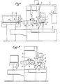
- Les figures 1, 2 et 3 sont des vues de face illustrant schématiquement une machine munie d'un dispositif selon l'invention dans la succession des positions d'extraction ou d'introduction d'outil ;
- La figure 4 est une vue de dessus de la même machine avec le changeur automatique dans la position représentée en pointillé figure 3 ;
- Les figures 5 et 6 sont des vues de face illustrant les positions du dispositif lorsque la pince est vide ;
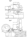
- Les figures 7 et 8 sont des vues de face et de dessus illustrant une variante dans laquelle le bras porte-pinces est muni de deux pinces.
- Figures 1, 2 and 3 are front views schematically illustrating a machine provided with a device according to the invention in the succession of tool extraction or insertion positions;
- Figure 4 is a top view of the same machine with the automatic changer in the position shown in dotted lines in Figure 3;
- Figures 5 and 6 are front views illustrating the positions of the device when the clamp is empty;
- Figures 7 and 8 are front and top views illustrating a variant in which the clamp holder arm is provided with two clamps.
En se reportant à ces figures, on voit que le dispositif est particulièrement conçu pour une machine dans laquelle la tête porte-broche 1 est montée sur un chariot 2 coulissant horizontalement par les glissières 3 sur une console 4 elle-même coulissant verticalement sur un montant ou bâti latéral 5, l'ensemble étant placé devant la table 6.Referring to these figures, it can be seen that the device is particularly designed for a machine in which the
En 7 est représentée, sur la figure 1, la potence portant les organes de commande 8 de la machine. On voit l'importance qu'il y a à maintenir dégagé le côté du chariot 2 opposé au bâti latéral 5, côté qui doit rester accessible à l'opérateur commandant la machine au moyen des commandes 8.In 7 is shown in Figure 1, the bracket carrying the
Le dispositif de changement automatique d'outil de l'invention est prévu pour opérer sur broche en position verticale, outil vers le bas.The automatic tool change device of the invention is intended to operate on a spindle in the vertical position, tool down.
Il se compose d'un bras 9 porte-pince 10 et des moyens de pivotement et de translation dudit bras dans un plan vertical unique 11 (figure 4), situé entre la table 6 et le montant fixe 5.It consists of an
La position du plan 11 est de préférence choisie de façon à contenir l'axe de la broche 12 en position verticale lorsque le chariot 2 est en fin de course arrière, ledit chariot venant se caler dans cette position pour l'opération de changement d'outil.The position of the
Le bras porte-pince 9 est monté pivotant autour de l'axe horizontal 13 perpendiculaire au plan 11 et l'axe 13 est lui-même monté sur un chariot 14 qui coulisse horizontalement et parallèlement au plan 11 sur un support fixe 26, approximativement au niveau que prend la collerette 16 du porte-outil 15 lorsque la broche 12 est en position verticale vers le bas.The
Au bras porte-pince 9 est associé un magasin 17 constitué pour présenter les porte-outils 15 à un poste de changement 18 dans lequel l'axe du porte-outil est vertical, l'outil vers le haut, le cône 19 vers le bas et la collerette 16 au niveau de la translation horizontale de la pince 10.Associated with the
La longueur de bras séparant la pince 10 de l'axe 13 est choisie en corrélation avec l'angle du cône 19 du porte-outil 15 de telle sorte, que le porte-outil pénètre sans frottement dans la broche 12 de la machine et/ou dans la case du magasin 17 situéeà l'emplacement 18. Cette condition impose une longueur minimum qui peut être dépassée.The arm length separating the
Dans l'exemple représente, le magasin 17 a la forme d'un plateau circulaire, rotatif selon un axe vertical 20, et portant à sa périphérie des alvéoles 21 destinées à recevoir les porte-outils 15. En variante, le magasin peut être réalisé sous la forme d'une chaîne dont les maillons portent les alvéoles 21. La variante en forme de plateau tournant convient pour un magas.in pouvant contenir jusqu'à 30 - 40 outils ; au-delà de ce nombre et notamment pour un magasin de l'ordre de 100 outils ou davantage, la variante en forme de chaîne (connue en soi et non représentée) est préférable pour limiter l'encombrement.In the example shown, the
La séquence des mouvements du dispositif de l'invention est la suivante :
- Le
chariot 2 étant en position arrière et le changeur d'outil dans la position d'attente de la figure 6, lechariot 14 est déplacé par translation vers labroche 12 jusqu'à ce que lapince 10 vienne en prise avec lacollerette 16 du porte-outil 15 (figure 1).
- The
carriage 2 being in the rear position and the tool changer in the standby position of FIG. 6, thecarriage 14 is moved in translation towards thespindle 12 until theclamp 10 comes into engagement with theflange 16 of the tool holder 15 (Figure 1).
Par une rotation du bras 9 vers le bas, le porte-outil 15 est complètement dégagé de la broche (figure 2).By rotating the
Une translation du chariot 14 vers le magasin 17 place l'axe 13 dans une position permettant la rotation du bras 9 sans interférence avec le chariot 2 (figure 3).A translation of the
La rotation du bras 9 transporte le porte-outil 15 dans l'alvéole 18 du magasin 17 (figure 3, pointillé et figure 4) (rotation de 180°).The rotation of the
Une translation du chariot 14 vers la broche 12 dégage la pince 10 de l'outil ainsi déposé dans le magasin (figure 5).A translation of the
Pour la mise en place d'un autre outil, placé au poste 18 par le magasin, le bras 9 subit la séquence de déplacements inverse, de la figure 5 à la figure 1, pour ensuite prendre la position d'attente de la figure 6.For the installation of another tool, placed at
Dans l'exemple représenté, le bras 9 ne porte qu'une seule pince 10. Mais il va de soi que le bras 9 peut être articulé en son centre sur l'axe 13 et porter deux pinces 10 opposées. Dans ce cas, deux mouvements de translation du chariot 13 seront prévus de part et d'autre de la position principale de rotation de la figure 3.In the example shown, the
Cette variante de réalisation est schématiquement représentée sur les figures 7 et 8.This variant embodiment is schematically represented in FIGS. 7 and 8.
Les mêmes organes ont les mêmes chiffres de référence que sur les figures 1 à 6. Le bras 9 est articulé en 13 en son centre et porte deux pinces 10a, 10b symétriques par rapport a l'axe 13.The same members have the same reference numbers as in FIGS. 1 to 6. The
Dans cette variante, la translation du bras 9 occupe trois positions principales, l'une vers la broche 12 correspondant à la mise en place et au retrait des outils, l'autre vers le magasin 17 pour le dépôt et la prise d'outii, et une position centrale de rotation à 180°. Dans les deux positions extrêmes, le bras 9 est soumis à la rotation nécessaire au dégagement de l'outil hors de la broche ou hors du magasin.In this variant, the translation of the
La variante des figures 7 et 8 permet de réduire le temps de changement d'outil.The variant of FIGS. 7 and 8 makes it possible to reduce the tool change time.
Il est à noter que les branches du bras 9 portant les pinces 10a et 10b ne sont pas nécessairement symétriques par rapport à l'axe 13 et peuvent être disposées comme les branches d'un V plus ou moins ouvert, ou même d'un Y si le bras 9 comporte trois branches.It should be noted that the branches of the
L'invention prévoit, en outre les dispositions préférentielles ci-après :
- Un détecteur placé dans la
pince 10 informe le système de commande de pivotement dubras 9 de la présence ou de l'absence d'un porte-outil 15 dans ladite pince lorsque la pince est vide, ce système de commande arrête la rotation dubras 9 de telle sorte que lapince 10 se trouve au niveau de lacollerette 16 des porte-outils 15 tant sur labroche 12 que sur leposte 18 dumagasin 17. Lorsqu'un porte-outil 15 est sur lapince 10, la rotation dubras 9 est autorisée selon la séquence exposée plus haut.
- A detector placed in the
clamp 10 informs the pivoting control system of thearm 9 of the presence or absence of atool holder 15 in said clamp when the clamp is empty, this control system stops the rotation of thearm 9 so that theclamp 10 is located at theflange 16 of thetool holders 15 both on thespindle 12 and on thestation 18 of themagazine 17. When atool holder 15 is on theclamp 10, the rotation of thearm 9 is authorized according to the sequence described above.
La forme de la pince 10 est complémentaire au profil de la collerette 16 et la pince 10 comprend un moyen élastique ou commandé (par exemple électriquement ou hydrauliquement) non représenté, assurant le serrage de la pince 10 sur la collerette 16 pendant la manipulation des outils ainsi que le desserrage automatique lorsque l'outil est serré dans la broche 12 ou déposé au poste 18 du magasin 17. La tête porte-broche 1 comprend un moyen de positionnement des porte-outils 15 selon une orientation constante par rapport à la pince 10 de façon à permettre l'introduction des lardons d'entraînement 22 de la broche 12 dans des encoches 23 prévues sur les collerettes 16. Une protubérance 24, coagissant avec l'une des encoches 23, est prévue sur la pince 10 pour la conservation de cette orientation pendant le transfert.The shape of the
Les alvéoles 21 du magasin ont une forme adaptée au cône 19 des porte-outils. Le magasin peut être chargé manuellement. Chaque alvéole 21 comporte en outre un élément fixe 25 (figure 1) analogue aux lardons 22 qui rend impossible l'introduction d'un porte-outils 15 dans le magasin selon une orientation autre que celle correspondant à. l'orientation de la broche 12 en position de chargement.The
Les mouvements de rotation et translation du bras 9 sont assurés par tous moyens appropriés, notamment hydrauliques. Dans l'exemple représenté, on a prévu des moteurs électriques à courant continu 27 associés à des réducteurs mécaniques entraînant des vis sans fin (ou vis à billes)..The rotational and translational movements of the
Ces mouvements sont de préférence asservis dans le cadre d'un système de commande numérique, et l'enchaînement en séquence des mouvements nécessaires au changement d'outil est de préférence piloté par le dispositif de programmation automatique qui assure la gestion des autres fonctions de la machine.These movements are preferably controlled as part of a digital control system, and the sequencing of the movements necessary for tool change is preferably controlled by the automatic programming device which manages the other functions of the machine.
La machine elle-même peut être de type très divers pour autant qu'elle comporte une position à broche 12 verticale permettant l'adaptation du dispositif de l'invention.The machine itself can be of a very diverse type as long as it has a
En particulier, la tête 1 peut être orientable ou non, le chariot 2 coulisser sur un bâti fixe ou sur une console mobile verticalement etc.In particular, the
Diverses variantes peuvent être adoptées sans sortir du cadre de l'invention. C'est ainsi que le plan 11, représenté dans l'exemple décrit, parallèle à l'axe de la table, peut être disposé en oblique de façon à éloigner le magasin 17 de la table.Various variants can be adopted without departing from the scope of the invention. Thus the
De même,la translation du chariot 14 peut être prévue oblique par rapport a l'horizontale pour autant que le système de pinces autorise une obliquité dans l'opération de prise de la collerette 16 du porte-outil.Similarly, the translation of the
Claims (10)
Priority Applications (1)
| Application Number | Priority Date | Filing Date | Title |
|---|---|---|---|
| AT82401223T ATE12601T1 (en) | 1981-08-12 | 1982-06-30 | AUTOMATIC TOOL CHANGER FOR A MACHINE TOOL. |
Applications Claiming Priority (2)
| Application Number | Priority Date | Filing Date | Title |
|---|---|---|---|
| FR8115587A FR2511283A1 (en) | 1981-08-12 | 1981-08-12 | AUTOMATIC TOOL CHANGE DEVICE FOR MACHINE TOOL |
| FR8115587 | 1981-08-12 |
Publications (2)
| Publication Number | Publication Date |
|---|---|
| EP0073687A1 true EP0073687A1 (en) | 1983-03-09 |
| EP0073687B1 EP0073687B1 (en) | 1985-04-10 |
Family
ID=9261407
Family Applications (1)
| Application Number | Title | Priority Date | Filing Date |
|---|---|---|---|
| EP82401223A Expired EP0073687B1 (en) | 1981-08-12 | 1982-06-30 | Automatic tool changing apparatus for machine tools |
Country Status (5)
| Country | Link |
|---|---|
| EP (1) | EP0073687B1 (en) |
| AT (1) | ATE12601T1 (en) |
| DE (1) | DE3262976D1 (en) |
| ES (1) | ES266901Y (en) |
| FR (1) | FR2511283A1 (en) |
Cited By (4)
| Publication number | Priority date | Publication date | Assignee | Title |
|---|---|---|---|---|
| US4700452A (en) * | 1984-12-28 | 1987-10-20 | Maho Aktiengesellschaft | Tool magazine |
| FR2608487A1 (en) * | 1986-04-09 | 1988-06-24 | Graffenstaden | Improvements to tool changers |
| EP0401719A2 (en) * | 1989-06-09 | 1990-12-12 | Gebr. Heller Maschinenfabrik GmbH | Exchangeable device for a tool spindle bearer for a machine tool |
| BE1005442A3 (en) * | 1991-10-14 | 1993-07-27 | Pegard Productics En Abrege Pe | Method and system for machining long elements, notably aeronautical metalelements |
Citations (6)
| Publication number | Priority date | Publication date | Assignee | Title |
|---|---|---|---|---|
| US3263300A (en) * | 1963-12-30 | 1966-08-02 | Motch Merryweather Machinery | Automatic tool change arrangement |
| FR1507373A (en) * | 1966-11-18 | 1967-12-29 | G S P Guillemin Sergot Pegard | Method and mechanism for automatic tool change on a machine tool |
| FR1556441A (en) * | 1967-02-04 | 1969-02-07 | ||
| GB1166193A (en) * | 1967-04-24 | 1969-10-08 | Monarch Machine Tool Co | Improvements in or relating to Machine Tools |
| US3932924A (en) * | 1971-07-16 | 1976-01-20 | Doall Company | Method of changing tools |
| FR2348013A1 (en) * | 1976-04-15 | 1977-11-10 | Ernault Somua H | Tool change for NC vertical mill - has cam tracks on spindle head to mechanically operate arm transferring tool from magazine |
-
1981
- 1981-08-12 FR FR8115587A patent/FR2511283A1/en active Granted
-
1982
- 1982-06-30 EP EP82401223A patent/EP0073687B1/en not_active Expired
- 1982-06-30 AT AT82401223T patent/ATE12601T1/en not_active IP Right Cessation
- 1982-06-30 DE DE8282401223T patent/DE3262976D1/en not_active Expired
- 1982-08-11 ES ES1982266901U patent/ES266901Y/en not_active Expired
Patent Citations (6)
| Publication number | Priority date | Publication date | Assignee | Title |
|---|---|---|---|---|
| US3263300A (en) * | 1963-12-30 | 1966-08-02 | Motch Merryweather Machinery | Automatic tool change arrangement |
| FR1507373A (en) * | 1966-11-18 | 1967-12-29 | G S P Guillemin Sergot Pegard | Method and mechanism for automatic tool change on a machine tool |
| FR1556441A (en) * | 1967-02-04 | 1969-02-07 | ||
| GB1166193A (en) * | 1967-04-24 | 1969-10-08 | Monarch Machine Tool Co | Improvements in or relating to Machine Tools |
| US3932924A (en) * | 1971-07-16 | 1976-01-20 | Doall Company | Method of changing tools |
| FR2348013A1 (en) * | 1976-04-15 | 1977-11-10 | Ernault Somua H | Tool change for NC vertical mill - has cam tracks on spindle head to mechanically operate arm transferring tool from magazine |
Cited By (5)
| Publication number | Priority date | Publication date | Assignee | Title |
|---|---|---|---|---|
| US4700452A (en) * | 1984-12-28 | 1987-10-20 | Maho Aktiengesellschaft | Tool magazine |
| FR2608487A1 (en) * | 1986-04-09 | 1988-06-24 | Graffenstaden | Improvements to tool changers |
| EP0401719A2 (en) * | 1989-06-09 | 1990-12-12 | Gebr. Heller Maschinenfabrik GmbH | Exchangeable device for a tool spindle bearer for a machine tool |
| EP0401719A3 (en) * | 1989-06-09 | 1991-03-20 | Gebr. Heller Maschinenfabrik GmbH | Exchangeable device for a tool spindle bearer for a machine tool |
| BE1005442A3 (en) * | 1991-10-14 | 1993-07-27 | Pegard Productics En Abrege Pe | Method and system for machining long elements, notably aeronautical metalelements |
Also Published As
| Publication number | Publication date |
|---|---|
| ES266901Y (en) | 1983-08-16 |
| FR2511283B1 (en) | 1984-08-17 |
| FR2511283A1 (en) | 1983-02-18 |
| ATE12601T1 (en) | 1985-04-15 |
| DE3262976D1 (en) | 1985-05-15 |
| ES266901U (en) | 1983-02-16 |
| EP0073687B1 (en) | 1985-04-10 |
Similar Documents
| Publication | Publication Date | Title |
|---|---|---|
| EP0907457B1 (en) | Storage device for machine tools | |
| EP0035952B1 (en) | Automatic tool changing device adaptable to be mounted on machine tools having a vertical or horizontal spindle, and automatic means for handling and positioning these tools in the spindles of machine tools | |
| FR2558401A1 (en) | MACHINE TOOL CAPABLE OF PERFORMING MACHINING OPERATIONS OF DIFFERENT TYPES, SUCH AS TURNING, MILLING AND DRILLING | |
| FR2585276A2 (en) | MACHINE EXECUTING VARIOUS MACHINING OPERATIONS SUCH AS TURNING, MILLING, BORING | |
| FR2532226A1 (en) | MACHINE TOOL WITH AUTOMATIC TOOL CHANGER | |
| FR2529127A1 (en) | AUTOMATIC TOOL CHANGE APPARATUS, TOOL STORE USED WITH THE APPARATUS, METHOD FOR SELECTIVELY ROTATING TOOL CARROUSEL, AND TOOL HOLDER ASSEMBLY | |
| EP0669185B1 (en) | Magazine for changing tools or workpieces on machine tools | |
| CH649021A5 (en) | MACHINE FOR MACHINING BY EROSIVE ELECTRIC DISCHARGES. | |
| FR2906179A1 (en) | Object transfer device for displacing object i.e. bottle, has frame supporting driving unit that displaces arm such that opening of object is displaced along initial trajectory portion, along direction perpendicular to support area | |
| EP0073687B1 (en) | Automatic tool changing apparatus for machine tools | |
| EP0037292A1 (en) | Tool magazine for an automatic tool changing device | |
| EP0130096A2 (en) | Apparatus for producing shirt cuffs | |
| FR2624412A1 (en) | MANIPULATOR AND ROBOTIC DEVICE IN PARTICULAR FOR SHEET BENDER | |
| EP1231017A1 (en) | High precision transfering device for placing a piece on an immobilized pallet | |
| EP0023351A1 (en) | Machine tool with automatic tool change | |
| FR2984787A1 (en) | Tool changer for tool magazine assigned to machining head, has translation unit movable to adjustment position of adjusting unit, where adjusting unit is movable to variable position of tool holder by movement of tool magazine about axis | |
| EP0087996B1 (en) | Work handling device for a machine tool, e.g. a lathe | |
| FR2639625A1 (en) | Device for the tape-winding of coils or of bars using a tape which may or may not be insulating | |
| EP0128811B1 (en) | Tool changing apparatus for machine tools | |
| EP0407537B1 (en) | Machine and method for machining and/or finishing molded or machined mechanical parts | |
| FR2651708A1 (en) | TOOL CHANGER DEVICE FOR MACHINE TOOL. | |
| FR2608487A1 (en) | Improvements to tool changers | |
| FR2594735A1 (en) | APPARATUS FOR TRANSFERRING WORKPIECES FOR MACHINE TOOLS | |
| FR2527494A3 (en) | Revolving magazine tool change - is mounted on swing arm on numerical machine and has magazine tools positioned in concentric circles | |
| FR2564355A1 (en) | Tool changing device for a milling machine with horizontal and vertical spindles. |
Legal Events
| Date | Code | Title | Description |
|---|---|---|---|
| PUAI | Public reference made under article 153(3) epc to a published international application that has entered the european phase |
Free format text: ORIGINAL CODE: 0009012 |
|
| AK | Designated contracting states |
Designated state(s): AT BE CH DE GB IT LI LU NL SE |
|
| 17P | Request for examination filed |
Effective date: 19830513 |
|
| ITF | It: translation for a ep patent filed |
Owner name: SAIC BREVETTI S.R.L. |
|
| GRAA | (expected) grant |
Free format text: ORIGINAL CODE: 0009210 |
|
| AK | Designated contracting states |
Designated state(s): AT BE CH DE GB IT LI LU NL SE |
|
| PG25 | Lapsed in a contracting state [announced via postgrant information from national office to epo] |
Ref country code: NL Effective date: 19850410 Ref country code: AT Effective date: 19850410 |
|
| REF | Corresponds to: |
Ref document number: 12601 Country of ref document: AT Date of ref document: 19850415 Kind code of ref document: T |
|
| REF | Corresponds to: |
Ref document number: 3262976 Country of ref document: DE Date of ref document: 19850515 |
|
| PG25 | Lapsed in a contracting state [announced via postgrant information from national office to epo] |
Ref country code: LU Free format text: LAPSE BECAUSE OF NON-PAYMENT OF DUE FEES Effective date: 19850630 |
|
| NLV1 | Nl: lapsed or annulled due to failure to fulfill the requirements of art. 29p and 29m of the patents act | ||
| BERE | Be: lapsed |
Owner name: CENTRE D'ETUDES DU FRAISAGE CEF Effective date: 19850630 |
|
| PLBE | No opposition filed within time limit |
Free format text: ORIGINAL CODE: 0009261 |
|
| STAA | Information on the status of an ep patent application or granted ep patent |
Free format text: STATUS: NO OPPOSITION FILED WITHIN TIME LIMIT |
|
| 26N | No opposition filed | ||
| PG25 | Lapsed in a contracting state [announced via postgrant information from national office to epo] |
Ref country code: LI Effective date: 19860630 Ref country code: CH Effective date: 19860630 |
|
| PG25 | Lapsed in a contracting state [announced via postgrant information from national office to epo] |
Ref country code: BE Effective date: 19860731 |
|
| REG | Reference to a national code |
Ref country code: CH Ref legal event code: PL |
|
| PGFP | Annual fee paid to national office [announced via postgrant information from national office to epo] |
Ref country code: SE Payment date: 19910619 Year of fee payment: 10 |
|
| PGFP | Annual fee paid to national office [announced via postgrant information from national office to epo] |
Ref country code: DE Payment date: 19910620 Year of fee payment: 10 |
|
| PGFP | Annual fee paid to national office [announced via postgrant information from national office to epo] |
Ref country code: GB Payment date: 19910625 Year of fee payment: 10 |
|
| ITTA | It: last paid annual fee | ||
| PG25 | Lapsed in a contracting state [announced via postgrant information from national office to epo] |
Ref country code: GB Effective date: 19920630 |
|
| PG25 | Lapsed in a contracting state [announced via postgrant information from national office to epo] |
Ref country code: SE Effective date: 19920701 |
|
| GBPC | Gb: european patent ceased through non-payment of renewal fee |
Effective date: 19920630 |
|
| PG25 | Lapsed in a contracting state [announced via postgrant information from national office to epo] |
Ref country code: DE Effective date: 19930302 |
|
| EUG | Se: european patent has lapsed |
Ref document number: 82401223.1 Effective date: 19930204 |