EP0128811B1 - Tool changing apparatus for machine tools - Google Patents
Tool changing apparatus for machine tools Download PDFInfo
- Publication number
- EP0128811B1 EP0128811B1 EP84401113A EP84401113A EP0128811B1 EP 0128811 B1 EP0128811 B1 EP 0128811B1 EP 84401113 A EP84401113 A EP 84401113A EP 84401113 A EP84401113 A EP 84401113A EP 0128811 B1 EP0128811 B1 EP 0128811B1
- Authority
- EP
- European Patent Office
- Prior art keywords
- tool
- sleeve
- block
- carriage
- axis
- Prior art date
- Legal status (The legal status is an assumption and is not a legal conclusion. Google has not performed a legal analysis and makes no representation as to the accuracy of the status listed.)
- Expired
Links
Images


Classifications
-
- B—PERFORMING OPERATIONS; TRANSPORTING
- B23—MACHINE TOOLS; METAL-WORKING NOT OTHERWISE PROVIDED FOR
- B23Q—DETAILS, COMPONENTS, OR ACCESSORIES FOR MACHINE TOOLS, e.g. ARRANGEMENTS FOR COPYING OR CONTROLLING; MACHINE TOOLS IN GENERAL CHARACTERISED BY THE CONSTRUCTION OF PARTICULAR DETAILS OR COMPONENTS; COMBINATIONS OR ASSOCIATIONS OF METAL-WORKING MACHINES, NOT DIRECTED TO A PARTICULAR RESULT
- B23Q3/00—Devices holding, supporting, or positioning work or tools, of a kind normally removable from the machine
- B23Q3/155—Arrangements for automatic insertion or removal of tools, e.g. combined with manual handling
- B23Q3/157—Arrangements for automatic insertion or removal of tools, e.g. combined with manual handling of rotary tools
- B23Q3/15773—Arrangements for automatic insertion or removal of tools, e.g. combined with manual handling of rotary tools a transfer device taking the tool from a storage device and passing it on to other transfer devices, which insert it in a spindle
Definitions
- the replacement tool must either be placed in advance on the double arm or be removed in the magazine simultaneously with the grip of the tool located in the spindle.
- Some devices provide a double arm with complex movement allowing the double arm to take a tool from the magazine during the working phase of the machine, so that the double arm is back in the change position, equipped with the tool. spare before the end of this work phase.
- This arrangement has the disadvantage of a position of the magazine which is inconvenient from the point of view of the operation of the machine tool, and requires a very rigorous position of the tool changing station on the magazine.
- the invention relates to improvements to machines of this type described for example in FR-A-2391809 and in particular making it possible to carry out in a simple and effective manner the various corrections of errors or deviations in positioning inherent in the manufacture and the games of operation, retrofits necessary for high speed automation with increased operational safety.
- the device according to the invention is defined in claim 1.
- Figure 1 there is schematically shown the frame of the machine tool at 1, the device according to the invention can be adapted to machines of various shapes.
- the machine tool 1 comprises a tool-holder spindle, not shown, whose axis in the tool changing position is vertical and shown in 2 (direction Z).
- the tool loading device of the invention comprises a magazine 3, a double arm 4 and a carriage 5 for the transfer of tools from the magazine 3 to the double arm 4.
- the magazine 3 can be of the disc type or pliers chain 9, the tools moving with their horizontal axis.
- the chain type magazine 3 solution is preferred because, for the same number of tools it occupies less space, such a magazine can easily be fixed on the lateral part of the upright of the machine frame, which frees up the area work, finally it is possible to provide a fairly low magazine loading station, at 10, easy for operators to access, while the station 11 for picking up the tool by the carriage can be placed much higher, relationship with the height of the machine spindle at the exchange station.
- the movements of the carriage 5 (along the Y axis) must ensure the movement of the tools from the magazine to the double arm 4 and their tilting with a vertical axis (Z axis) which, in itself, is known and be carried out in different ways. manners.
- the double arm 4 is of known constitution, with two clamps 6 and 7 symmetrical with respect to the axis 8.
- the axis 8 is vertical and fixed relative to the frame 1 of the machine, and the arm has two freedom of movement: a) sliding along the axis 8 between a tool grip position, both on the spindle and on the carriage 5, and a tool release position; b) 180 ° rotation allowing the exchange of tools in combination with the previous slide.
- the carriage 5 returns to the magazine 3, the selection of a new tool and its transfer to the exchange position while the machine tool is in the working phase, so that the transfer time between store 3 and exchange station is not taken from the working time of the machine.
- the carriage 5 slides on horizontal slides fixed relative to the frame, in this case the bars 12 and 13 under the action of a jack 14 whose rod is connected to the carriage 5 by means of a spring 16, while a stop 17 is provided to limit the movement of the carriage 5 towards the spindle.
- the exchange position of the carriage 5 is rigorously defined along the Y axis with respect to spindle 2, while in the opposite position, the carriage 5 is capable of displacement along the Y axis for the catches of games and spreads.
- a single spring 16 and that the part 18 for connecting the carriage to the rod 15 is taken between a stop not shown and the spring 16 placed on the side of the spindle so that there is no positioning clearance when the carriage 5 is against the stop 17 while there is an elastic clearance in one direction when the carriage 5 is in its position close to the magazine and the cylinder stroke is established by so that this position is systematically in excess towards the magazine, the closing of the clamp 9 elastically pushing the carriage 5 against the spring 16.
- the carriage 5 carries a block 19 rocking about a horizontal axis 20 and perpendicular to the direction of the tools in the magazine (axis X), under the action of a jack 21 carried by the carriage 5.
- the block 19 brought to in turn a sleeve 22 for tool holder; sleeve 22 slides in the block perpendicular to the axis 20.
- the sleeve 22 slides by the gusset 26 on a 25 carried by the block 19, the movements of the gusset 26 being limited downwards (exchange position) by the stop 24.
- the sleeve 22 has a possibility of oscillations of limited amplitude around the shaft 25; the sleeve 22 carries for this purpose pads 27 or bearings 28 constrained by springs 48 which slide on the flat face 29 of the block and maintain the surface 30 of the sleeve parallel to the surface 29.
- a fork 30 which when the carriage 5 is in position close to the magazine 3 comes to cooperate with the end of the rod of the jack 32, fixed relative to the magazine 3, to the frame 1 and slides 12 and 13.
- This connection with the end 31 of the jack 32 is made elastic in at least one direction by two springs 33 enclosing a diabolo 47.
- the jack 32 ensures the movements of withdrawal of a tool from the clamp 11 (or placement of a tool in the clamp) and in this position, the springs 33 take up the play of position of the clamp 9 along the axis X.
- the block 19 is held in the raised position by the tilt cylinder 21.
- the rear stop 34 sliding against the slide 35 fixed in relation slides 12 and 13 and the frame 1, maintains the sleeve 22 in the advanced position.
- the end of the slide 35, store side is positioned so that the sleeve 22 can move back to release the cone of the tool carried by the pliers 9 of the store.
- the recoil of the sleeve 22 is effected by the penetration of the fork 30 into the diablo 47 actuated by the jack 32.
- the tilting of the block 19 is not hampered by the presence of the slide 35.
- the cams 39, 40 are preferably flat faces cut from rotary shafts 41, 42 in the sleeve 22 and carrying the pinions 43, 44 on which the rack 45 acts. The latter is constantly pushed by the spring 46 towards the position of restraint. A cylinder 47 internal to the sleeve 22 ensures the release of the tool against the spring 46.
Landscapes
- Engineering & Computer Science (AREA)
- Mechanical Engineering (AREA)
- Automatic Tool Replacement In Machine Tools (AREA)
Abstract
Description
La technique du changement d'outil automatique est déjà ancienne et a fait l'objet de nombreux brevets- Certains d'entre eux comportent l'usage d'un bras double symétrique à deux pinces d'extrémités, ce qui permet d'effectuer le changement d'outil par déplacements du bras selon son axe combinés avec une rotation de 180°, et l'invention se rapporte à un changeur d'outil de ce type.The technique of automatic tool change is already old and has been the subject of numerous patents. Some of them include the use of a symmetrical double arm with two end pliers, which allows the tool change by movement of the arm along its axis combined with a rotation of 180 °, and the invention relates to a tool changer of this type.
Cependant, pour que l'opération soit exécutée rapidement, il faut que l'outil de rechange soit, ou bien placé d'avance sur le bras double ou bein prélevé dans le magasin simulanément à la prise de l'outil situé dans la broche.However, for the operation to be carried out quickly, the replacement tool must either be placed in advance on the double arm or be removed in the magazine simultaneously with the grip of the tool located in the spindle.
Certains dispositifs prévoient un bras double à mouvement complexe permettant au bras double d'aller prélever un outil sur le magasin pendant la phase de travail de la machine, de sorte que le bras double soit de retour en position de changement, muni de l'outil de rechange avant la fin de cette phase de travail.Some devices provide a double arm with complex movement allowing the double arm to take a tool from the magazine during the working phase of the machine, so that the double arm is back in the change position, equipped with the tool. spare before the end of this work phase.
Cette solution est d'une grande complication mécanique compte tenu des précisions de positions nécessaires à l'automatisation des mouvements.This solution is a great mechanical complication, taking into account the position specifications necessary for the automation of movements.
D'autres dispositifs prévoient de placer le magasin de telle sorte que l'outil de rechange présente en position symétrique de celle de l'outil sur la broche en position de changement.Other devices provide for placing the magazine so that the replacement tool has a position symmetrical to that of the tool on the spindle in the changing position.
Cette disposition a pour inconvénient une position du magasin qui est incommode du point de vue du fonctionnement de la machine-outil, et exige une très grande rigueur de position du poste de changement d'outil sur le magasin.This arrangement has the disadvantage of a position of the magazine which is inconvenient from the point of view of the operation of the machine tool, and requires a very rigorous position of the tool changing station on the magazine.
Pour résoudre ces problèmes, il a déjé été proposé de placer le magasin à l'emplacement le plus avantageux et de prévoir un chariot de transfert entre le magasin et le bras double, ce chariot ayant pour fonction de prélever l'outil suivant dans magasin et de l'amener en position symétrique de l'outil en broche pendant la phase de travail de la machine, de sorte que les mouvements du bras double puissent être réduits au minimum, et exécutés rapidement en toute sécurité.To solve these problems, it has already been proposed to place the magazine in the most advantageous location and to provide a transfer cart between the magazine and the double arm, this cart having the function of taking the next tool from the magazine and bring it to a symmetrical position of the spindle tool during the working phase of the machine, so that the movements of the double arm can be reduced to a minimum, and executed quickly and safely.
L'invention se rapporte à des perfectionnements aux machines de ce type décrites par exemple dans FR-A-2391809 et permettant notamment de réaliser de façon simple et efficace les divers rattrapages d'erreurs ou écarts de positionnement inhérentes à la fabrication et aux jeux de fonctionnement, rattrapages nécessaires à une automatisation de cadence élevée avec une sécurité de fonctionnement accrue.The invention relates to improvements to machines of this type described for example in FR-A-2391809 and in particular making it possible to carry out in a simple and effective manner the various corrections of errors or deviations in positioning inherent in the manufacture and the games of operation, retrofits necessary for high speed automation with increased operational safety.
Le dispositif selon l'invention est defini dans la revendication 1.The device according to the invention is defined in claim 1.
Par cet ensemble de dispositions, on obtient une position fixe et sûre de l'outil lorsque le chariot est en position de changement d'outil, du fait que les positions du manchon dans le bloc, du bloc dans le chariot et du chariot sur les barres sont définies par des butées positives; le bras double peut alors, en toute sécurité effectuer les manoeuvres de prise d'outil simultanées sur la broche et le chariot, l'extraction des outils et leur échange par rotation de 180° et coulissement inverse.By this set of provisions, a fixed and secure position of the tool is obtained when the carriage is in the tool change position, owing to the fact that the positions of the sleeve in the block, of the block in the carriage and of the carriage on the bars are defined by positive stops; the double arm can then safely carry out the simultaneous tool gripping maneuvers on the spindle and the carriage, the extraction of the tools and their exchange by 180 ° rotation and reverse sliding.
A l'opposé, lorsque le chariot est en position de coopération avec le magasin, les écarts de positionnement pouvant atteindre 1 mm sont aisément absorbés dans les trois directions de l'espace ainsi qu'il sera exposé plus en détail ultérieurement, ce qui est d'un grand avantage tant à la fabrication qu'au fonctionnement parce que les magasins, en particulier les magasins à chaine, ne peuvent pas être réalisés avec une précision absolue en ce qui concerne la position de l'outil au poste de chargement.On the other hand, when the trolley is in the position of cooperation with the store, the positioning deviations of up to 1 mm are easily absorbed in the three directions of the space, as will be explained in more detail later, which is of great advantage both in manufacturing and in operation because the magazines, in particular the chain magazines, cannot be produced with absolute precision as regards the position of the tool at the loading station.
L'invention peut inclure les caractéristiques suivantes:
- a) Le coulissement du manchon dans le bloc est commandé, par l'extrémité de la tige d'un vérin situé en position fixe par rapport au magasin et le manchon porte une fourchette qui vient coopérer avec un diabolo monté entre deux ressorts sur ladite extrémité de tige de vérin lorsque le chariot est en position de prise ou de remise d'outil dans le magasin.
- b) Le manchon coulisse dans le bloc sur un arbre porté par ledit bloc, perpendiculaire à l'axe de basculement du bloc et il est maintenu en position angulaire avec jeu d'oscillations par des patins portés par le manchon et contretenus par ressorts, ces patins glissant sur des surfaces planes du bloc parallèles à l'arbre de coulissement.
- c) La retenue d'un outil dans le manchon est obtenue par la rotation de deux cames situées de part et d'autre d'un bouton terminal porté par la queue de l'outil, cette rotation résultant de l'action d'une crémaillère commune agissant sur des pignons portés par les arbres porte-cames.
- d) De préférence, cette crémaillère est contretenue par ressort dans le sens de la retenue de l'outil, un vérin étant prévu pour assurer le relâchement en repoussant la crémaillère à l'encontre du ressort.
- e) Le bloc porté par le chariot est maintenu en position relevée pendant le transfert et le coulissement du manchon vers l'arrière est empêché par appui d'une butée portée par ledit manchon sur une glissière fixe par rapport au magasin dont l'extrémité proche du magasin est placé de telle sorte que le manchon ne peut coulisser que lorsque le chariot est en position de coopération avec le magasin.
- a) The sliding of the sleeve in the block is controlled by the end of the rod of a jack situated in a fixed position relative to the magazine and the sleeve carries a fork which comes to cooperate with a diabolo mounted between two springs on said end cylinder rod when the carriage is in the tool take-up or return position in the magazine.
- b) The sleeve slides in the block on a shaft carried by said block, perpendicular to the axis of tilting of the block and it is kept in angular position with a set of oscillations by pads carried by the sleeve and constrained by springs, these glides sliding on flat surfaces of the block parallel to the sliding shaft.
- c) The retention of a tool in the sleeve is obtained by the rotation of two cams located on either side of a terminal button carried by the tail of the tool, this rotation resulting from the action of a common rack acting on pinions carried by camshafts.
- d) Preferably, this rack is constrained by spring in the direction of the retention of the tool, a jack being provided to ensure relaxation by pushing the rack against the spring.
- e) The block carried by the carriage is held in the raised position during the transfer and the sliding of the sleeve backwards is prevented by pressing a stop carried by said sleeve on a slide fixed relative to the store whose near end of the magazine is placed so that the sleeve can slide only when the carriage is in the position of cooperation with the magazine.
Une réalisation de l'invention sera plus amplement décrite avec référence aux dessins annexés sur lequel:
- La figure 1 est une vue schématique d'ensemble du dispositif.
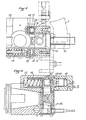
- Les figures 2, 3, 4, sont des vues de détail de l'ensemble bloc basculant et manchon coulissant; figure 2 coupe selon les axes de basculement et de coulissement; figure 3 vue en bout du manchon avec arrachement partiel; figure 4 coupe partielle selon AA de la figure 2.
- Figure 1 is a schematic overview of the device.
- Figures 2, 3, 4, are detail views of the tilting block and sliding sleeve assembly; Figure 2 section along the axes of tilting and sliding; Figure 3 end view of the sleeve with partial cutaway; Figure 4 partial section along AA of Figure 2.
Sur la figure 1, on a schématiquement représenté le bâti de la machine-outil en 1, le dispositif selon l'invention pouvant être adapté à des machines de formes diverses.In Figure 1, there is schematically shown the frame of the machine tool at 1, the device according to the invention can be adapted to machines of various shapes.
La machine-outil 1 comporte une broche porte-outil, non représentée, dont l'axe en position de changement d'outil est vertical et représenté en 2 (direction Z).The machine tool 1 comprises a tool-holder spindle, not shown, whose axis in the tool changing position is vertical and shown in 2 (direction Z).
Le dispositif de chargement d'outil de l'invention comporte un magasin 3, un bras double 4 et un chariot 5 pour le transfert des outils depuis le magasin 3 jusqu'au bras double 4. Le magasin 3 peut êter du type à disque ou à chaîne porte- pinces 9, les outils se déplaçant avec leur axe horizontal. La solution du magasin 3 du type à chaîne est préférée car, pour un même nombre d'outil elle occupe moins de place, un tel magasin peut aisément êter fixé sur la partie latérale du montant du bâti de la machine, ce qui libère la zone de travail, enfin il est possible de prévoir un poste de chargement du magasin assez bas, en 10, facile d'accès pour les opérateurs, tandis que le poste 11 de prélèvement d'outil par le chariot peut êter placé beaucoup plus haut, en relation avec la hauteur de la broche de la machine au poste d'échange.The tool loading device of the invention comprises a magazine 3, a
Les mouvements du chariot 5 (selon l'axe Y) doivent assurer le déplacement des outils depuis le magasin jusqu'au bras double 4 et leur basculement à axe vertical (axe Z) ce qui, en soi, est connu et être réalisé de différentes manières.The movements of the carriage 5 (along the Y axis) must ensure the movement of the tools from the magazine to the
Le bras double 4 est de constitution connue, avec deux pinces 6 et 7 symétriques par rapport à l'axe 8. L'axe 8 est vertical et fixe par rapport au bâti 1 de la machine, et le bras a deux libertés de mouvement: a) coulissement selon l'axe 8 entre une position de prise d'outil, à la fois sur la broche et sur le chariot 5, et une position de dégagement des outils; b) rotation de 180° permettant l'échange des outils en combinaison avec le coulissement précédent.The
Avec un dispositif de ce type dans lequel les mouvements du bras double sont simples: rotation de prise des outils, dégagement des outils, rotation d'échange, mise en place des outils et retour en position neutre, l'échange des outils peut être réalisé de façon rapide et sûre, compatible avec une automatisation poussée.With a device of this type in which the movements of the double arm are simple: rotation of grip of the tools, release of the tools, rotation of exchange, positioning of the tools and return to neutral position, the exchange of the tools can be carried out quickly and safely, compatible with advanced automation.
Une fois l'outil échangé, le chariot 5 effectue le retour au magasin 3, la sélection d'un nouvel outil et son transfert en position d'échange pendant que la machine-outil est en cours de phase de travail, de sorte que les temps de transfert entre magasin 3 et poste d'échange ne sont pas pris sur le temps de travail de la machine.Once the tool has been exchanged, the
Cependant, pour qu'un tel dispositif fonctionne de manière fiable, il est nécessaire que la position de l'outil au poste d'échange soit très rigoureuse et précise, tandis qu'au poste de prise d'outil ou de remise d'outil par le chariot 5 dans le magasin 3, il est nécessaire de pouvoir rattraper les tolérances de positions des pinces du magasin. En effet, particulièrement lorsqu'il s'agit d'un magasin du type à chaîne comme représenté, les jeux de fonctionnement de la chaîne et les écarts de positionnement d'arrêt d'un outil au poste de chargement 17 du chariot peuvent atteindre jusqu'à 1 mm environ dans les trois directions de l'espace.However, for such a device to operate reliably, it is necessary that the position of the tool at the exchange station is very rigorous and precise, while at the tool pick-up or tool delivery station by the
Dans ce but, le chariot 5 coulisse sur glissières horizontales fixes par rapport au bâti, en l'espèce les barres 12 et 13 sous l'action d'un vérin 14 dont la tige est reliée au chariot 5 par l'intermédiaire d'un ressort 16, tandis qu'une butée 17 est prévue pour limiter le déplacement du chariot 5 vers la broche. Ainsi, la position d'échange du chariot 5 est rigoureusement défini selon l'axe Y par rapport à de broche 2, tandis qu'en position opposée, le chariot 5 est susceptible d'un déplacement selon l'axe Y pour les rattrapages de jeux et d'écarts.For this purpose, the
Conformément à l'invention, il est préféré d'utiliser un seul ressort 16 et que la pièce 18 de liaision du chariot à la tige 15 soit prise entre une butée non représentée et le ressort 16 placé du côté de la broche de sorte qu'il n'y a aucun jeu de positionnement lorsque le chariot 5 est contre la butée 17 tandis qu'il y a un jeu élastique dans un seul sens lorsque le chariot 5 est dans sa position proche du magasin et la course du vérin est établie de telle sorte que cette position soit systématiquement en excès vers le magasin, la fermeture de la pince 9 repoussant élastiquement le chariot 5 à l'encontre du ressort 16.According to the invention, it is preferred to use a single spring 16 and that the
Le chariot 5 porte un bloc 19 basculant autour d'un axe 20 horizontal et perpendiculare à la direction des outils dans le magasin (axe X), sous l'action d'un vérin 21 porté par le chariot 5. Le bloc 19 porté à son tour un manchon 22 porte-outil; manchon 22 coulisse dans le bloc perpendiculairement à l'axe 20.The
Dans la forme préférée de réalisation qui est représentée, le manchon 22 coulisse par le gousset 26 sur un 25 porté par le bloc 19, les déplacements du gousset 26 étant limités vers le bas (position d'échange) par la butée 24. En outre, le manchon 22 possède une possibilité d'oscillations d'amplitude limitée autour de l'arbre 25; le manchon 22 porte à cet effet des patins 27 ou roulements 28 contretenus par ressorts 48 qui glissent sur la face plane 29 du bloc et maintiennent la surface 30 du manchon parallèle à la surface 29.In the preferred embodiment which is shown, the
Ainisi, lorsque le chariot 5 est en position d'échange d'outil (représentée en pointillé sur la partie droite de la figure), le machon porte-outil 22 se trouve en appui sur la butée 24 par le gousset 26, du fait de son propre poids. La position du manchon 22 selon l'axe Z est donc rigoureusement déterminée.Thus, when the
Par contre, dans la position du chariot 5 proche du magasin 3, le bloc 19 étant relevé le jeu d'oscillations du manchon 22 autour de l'axe 25 permet un léger déplacement selon l'axe Z et le rattrapage du jeu de position de la pince 9 selon cet axe, dans la position 11.On the other hand, in the position of the
D'autre part, au manchon 22 est liée une fourchette 30, qui lorsque le chariot 5 est en position proche du magasin 3 vient coopérer avec l'extrémité de la tige du vérin 32, fixe par rapport au magasin 3, au bâti 1 et aux glissières 12 et 13. Cette liaison avec l'extrémité 31 du vérin 32 est rendue élastique dans au moins un sens par deux ressorts 33 enserrant un diabolo 47. Le verin 32 assure les mouvements de retrait d'un outil hors de la pince 11 (ou de placement d'un outil dans la pince) et dans cette position, les ressorts 33 assurent le rattrapage des jeux de position de la pince 9 selon l'axe X.On the other hand, to the
De préférence, pendant la phase de déplacement du chariot 5 (axe Y) sur les glissières 12 et 13, le bloc 19 est maintenu en position relevée par le vérin de basculemet 21. La butée arrière 34, coulissant contre la glissière 35 fixe en rapport aux glissières 12 et 13 et au bâti 1, maintient le manchon 22 en position avancée. L'extémité de la glissière 35, côté magasin, est positionnée de telle sorte que le manchon 22 peut reculer pour dégager le cône de l'outil porté par les pinces 9 du magasin. Le recul du manchon 22 se fait par la pénétration de la fourchette 30 dans le diablo 47 actionné par le vérin 32. Côté bras double, le basculement du bloc 19 n'est pas entravé par la présence de la glissière 35.Preferably, during the movement phase of the carriage 5 (axis Y) on the
La retenue d'un outil 36 dans le manchon 22 est réalisée par des cames 39, 40 agissant sur le bouton 37 placé à l'extrémité de la queue de l'outil, de telle sorte que la rainure 38 reste libre pour l'action du bras double 4 ou de la pince 9.The retention of a
Les cames 39, 40 sont de préférence des faces planes taillées dans des arbres 41,42 rotatifs dans le manchon 22 et portant les pignons 43, 44 sur lesquels agit la crémaillère 45. Celle-ci est constammet repoussée par le ressort 46 vers la position de retenue. Un vérin 47 interne au manchon 22, assure la libératon de l'outil à l'encontre du ressort 46.The
Claims (6)
Priority Applications (1)
| Application Number | Priority Date | Filing Date | Title |
|---|---|---|---|
| AT84401113T ATE20843T1 (en) | 1983-06-03 | 1984-05-30 | TOOL CHANGER DEVICES FOR MACHINE TOOLS. |
Applications Claiming Priority (2)
| Application Number | Priority Date | Filing Date | Title |
|---|---|---|---|
| FR8309244A FR2546794B1 (en) | 1983-06-03 | 1983-06-03 | IMPROVEMENTS ON TOOL CHANGER DEVICES FOR MACHINE TOOLS |
| FR8309244 | 1983-06-03 |
Publications (2)
| Publication Number | Publication Date |
|---|---|
| EP0128811A1 EP0128811A1 (en) | 1984-12-19 |
| EP0128811B1 true EP0128811B1 (en) | 1986-07-23 |
Family
ID=9289462
Family Applications (1)
| Application Number | Title | Priority Date | Filing Date |
|---|---|---|---|
| EP84401113A Expired EP0128811B1 (en) | 1983-06-03 | 1984-05-30 | Tool changing apparatus for machine tools |
Country Status (4)
| Country | Link |
|---|---|
| EP (1) | EP0128811B1 (en) |
| AT (1) | ATE20843T1 (en) |
| DE (1) | DE3460342D1 (en) |
| FR (1) | FR2546794B1 (en) |
Families Citing this family (4)
| Publication number | Priority date | Publication date | Assignee | Title |
|---|---|---|---|---|
| FR2564352B1 (en) * | 1984-05-21 | 1988-10-21 | Vernier Sa | DEVICE FOR TRANSFERRING AND STORING TOOLS FOR MILLING MACHINES, MACHINING CENTERS AND THE LIKE |
| FR2608487A1 (en) * | 1986-04-09 | 1988-06-24 | Graffenstaden | Improvements to tool changers |
| JP2001062660A (en) * | 1999-08-27 | 2001-03-13 | Mori Seiki Co Ltd | Tool transfer equipment for machine tools |
| DE102021131810A1 (en) * | 2021-12-02 | 2023-06-07 | Chiron Group Se | Tool changing device, machine tool and method for changing a tool |
Family Cites Families (4)
| Publication number | Priority date | Publication date | Assignee | Title |
|---|---|---|---|---|
| US4196506A (en) * | 1976-09-07 | 1980-04-08 | Giddings & Lewis, Inc. | Tool changer machining center |
| JPS5839620B2 (en) * | 1977-02-04 | 1983-08-31 | 株式会社山崎鉄工所 | tool shifter |
| FR2391809A1 (en) * | 1977-05-25 | 1978-12-22 | Ratier Sa Forest | Machining station with tool magazine - having coaxial circular plates mounted on axle normal w.r.t. slide mounted tool spindle and pivoting pick=up to align tool |
| US4288909A (en) * | 1978-10-25 | 1981-09-15 | Kearney & Trecker Corporation | Automatic tool changer for machine tool |
-
1983
- 1983-06-03 FR FR8309244A patent/FR2546794B1/en not_active Expired
-
1984
- 1984-05-30 EP EP84401113A patent/EP0128811B1/en not_active Expired
- 1984-05-30 DE DE8484401113T patent/DE3460342D1/en not_active Expired
- 1984-05-30 AT AT84401113T patent/ATE20843T1/en not_active IP Right Cessation
Also Published As
| Publication number | Publication date |
|---|---|
| ATE20843T1 (en) | 1986-08-15 |
| FR2546794A1 (en) | 1984-12-07 |
| FR2546794B1 (en) | 1986-05-23 |
| EP0128811A1 (en) | 1984-12-19 |
| DE3460342D1 (en) | 1986-08-28 |
Similar Documents
| Publication | Publication Date | Title |
|---|---|---|
| EP0068952B1 (en) | High productivity machine tools | |
| EP0185286B1 (en) | Method for automatically loading work stations, and device for carrying out said method | |
| EP0669185B1 (en) | Magazine for changing tools or workpieces on machine tools | |
| CH636543A5 (en) | MACHINE TOOL COMPRISING TWO OPPOSITE COAXIAL SPINDLES. | |
| FR2585276A2 (en) | MACHINE EXECUTING VARIOUS MACHINING OPERATIONS SUCH AS TURNING, MILLING, BORING | |
| FR2609660A1 (en) | MILLING MACHINE, IN PARTICULAR FOR GRINDING SCISSOR BRANCHES | |
| EP0032890A1 (en) | Machining centre-type machine tools | |
| FR2488825A1 (en) | MACHINE TOOL WITH QUICK CHANGE OF AUTOMATIC TOOL | |
| EP0128811B1 (en) | Tool changing apparatus for machine tools | |
| EP0473747B1 (en) | Metal-working machine, in particular for bar machining | |
| EP1231017A1 (en) | High precision transfering device for placing a piece on an immobilized pallet | |
| CH659020A5 (en) | INDUSTRIAL ROBOT. | |
| EP0416003B1 (en) | Revolving head for machine tool | |
| EP0052023B1 (en) | Numerically controlled machine tool with tool magazine | |
| CH620630A5 (en) | Track for supporting and transporting components for a transfer machine | |
| CH673607A5 (en) | Multipurpose machine tool - with flexibility enhanced by using large number of its working axes | |
| EP1610926A1 (en) | Workbench for preparing a workpiece to be machined on a digitally controlled machine | |
| FR2467052A1 (en) | Robot tool-change for lathe - uses step rotating tool and magazine wheels on parallel axes with latter reciprocating axially to effect change | |
| FR2594735A1 (en) | APPARATUS FOR TRANSFERRING WORKPIECES FOR MACHINE TOOLS | |
| EP0443019A1 (en) | Tool-changing device for machine-tools | |
| EP0073687A1 (en) | Automatic tool changing apparatus for machine tools | |
| FR2564352A1 (en) | Tool transfer and storage device for milling machines, machining centres and similar machines | |
| FR2527494A3 (en) | TOOL CHANGING DEVICE FOR WORKING CENTERS WITH LARGE CAPACITY TOOLING STORE | |
| EP0329527A1 (en) | Supply and removal device for the tools of a vertical broaching machine | |
| FR2608487A1 (en) | Improvements to tool changers |
Legal Events
| Date | Code | Title | Description |
|---|---|---|---|
| PUAI | Public reference made under article 153(3) epc to a published international application that has entered the european phase |
Free format text: ORIGINAL CODE: 0009012 |
|
| AK | Designated contracting states |
Designated state(s): AT BE CH DE FR GB IT LI LU NL SE |
|
| 17P | Request for examination filed |
Effective date: 19850109 |
|
| GRAA | (expected) grant |
Free format text: ORIGINAL CODE: 0009210 |
|
| RAP1 | Party data changed (applicant data changed or rights of an application transferred) |
Owner name: COMPAGNIE INTELAUTOMATISME |
|
| AK | Designated contracting states |
Kind code of ref document: B1 Designated state(s): AT BE CH DE FR GB IT LI LU NL SE |
|
| PG25 | Lapsed in a contracting state [announced via postgrant information from national office to epo] |
Ref country code: NL Effective date: 19860723 Ref country code: IT Free format text: LAPSE BECAUSE OF FAILURE TO SUBMIT A TRANSLATION OF THE DESCRIPTION OR TO PAY THE FEE WITHIN THE PRESCRIBED TIME-LIMIT;WARNING: LAPSES OF ITALIAN PATENTS WITH EFFECTIVE DATE BEFORE 2007 MAY HAVE OCCURRED AT ANY TIME BEFORE 2007. THE CORRECT EFFECTIVE DATE MAY BE DIFFERENT FROM THE ONE RECORDED. Effective date: 19860723 Ref country code: AT Effective date: 19860723 |
|
| REF | Corresponds to: |
Ref document number: 20843 Country of ref document: AT Date of ref document: 19860815 Kind code of ref document: T |
|
| PG25 | Lapsed in a contracting state [announced via postgrant information from national office to epo] |
Ref country code: SE Effective date: 19860731 |
|
| REF | Corresponds to: |
Ref document number: 3460342 Country of ref document: DE Date of ref document: 19860828 |
|
| NLV1 | Nl: lapsed or annulled due to failure to fulfill the requirements of art. 29p and 29m of the patents act | ||
| PLBE | No opposition filed within time limit |
Free format text: ORIGINAL CODE: 0009261 |
|
| PG25 | Lapsed in a contracting state [announced via postgrant information from national office to epo] |
Ref country code: LU Free format text: LAPSE BECAUSE OF NON-PAYMENT OF DUE FEES Effective date: 19870531 Ref country code: LI Effective date: 19870531 Ref country code: CH Effective date: 19870531 |
|
| 26N | No opposition filed | ||
| BERE | Be: lapsed |
Owner name: CIE INTELAUTOMATISME Effective date: 19870531 |
|
| REG | Reference to a national code |
Ref country code: CH Ref legal event code: PL |
|
| PG25 | Lapsed in a contracting state [announced via postgrant information from national office to epo] |
Ref country code: BE Effective date: 19890531 |
|
| PGFP | Annual fee paid to national office [announced via postgrant information from national office to epo] |
Ref country code: GB Payment date: 19920506 Year of fee payment: 9 |
|
| PGFP | Annual fee paid to national office [announced via postgrant information from national office to epo] |
Ref country code: DE Payment date: 19920521 Year of fee payment: 9 |
|
| PGFP | Annual fee paid to national office [announced via postgrant information from national office to epo] |
Ref country code: FR Payment date: 19920527 Year of fee payment: 9 |
|
| PG25 | Lapsed in a contracting state [announced via postgrant information from national office to epo] |
Ref country code: GB Effective date: 19930530 |
|
| GBPC | Gb: european patent ceased through non-payment of renewal fee |
Effective date: 19930530 |
|
| PG25 | Lapsed in a contracting state [announced via postgrant information from national office to epo] |
Ref country code: FR Effective date: 19940131 |
|
| PG25 | Lapsed in a contracting state [announced via postgrant information from national office to epo] |
Ref country code: DE Effective date: 19940201 |
|
| REG | Reference to a national code |
Ref country code: FR Ref legal event code: ST |