EP0128811B1 - Werkzeugwechselvorrichtungen für Werkzeugmaschinen - Google Patents
Werkzeugwechselvorrichtungen für Werkzeugmaschinen Download PDFInfo
- Publication number
- EP0128811B1 EP0128811B1 EP84401113A EP84401113A EP0128811B1 EP 0128811 B1 EP0128811 B1 EP 0128811B1 EP 84401113 A EP84401113 A EP 84401113A EP 84401113 A EP84401113 A EP 84401113A EP 0128811 B1 EP0128811 B1 EP 0128811B1
- Authority
- EP
- European Patent Office
- Prior art keywords
- tool
- sleeve
- block
- carriage
- axis
- Prior art date
- Legal status (The legal status is an assumption and is not a legal conclusion. Google has not performed a legal analysis and makes no representation as to the accuracy of the status listed.)
- Expired
Links
Images


Classifications
-
- B—PERFORMING OPERATIONS; TRANSPORTING
- B23—MACHINE TOOLS; METAL-WORKING NOT OTHERWISE PROVIDED FOR
- B23Q—DETAILS, COMPONENTS, OR ACCESSORIES FOR MACHINE TOOLS, e.g. ARRANGEMENTS FOR COPYING OR CONTROLLING; MACHINE TOOLS IN GENERAL CHARACTERISED BY THE CONSTRUCTION OF PARTICULAR DETAILS OR COMPONENTS; COMBINATIONS OR ASSOCIATIONS OF METAL-WORKING MACHINES, NOT DIRECTED TO A PARTICULAR RESULT
- B23Q3/00—Devices holding, supporting, or positioning work or tools, of a kind normally removable from the machine
- B23Q3/155—Arrangements for automatic insertion or removal of tools, e.g. combined with manual handling
- B23Q3/157—Arrangements for automatic insertion or removal of tools, e.g. combined with manual handling of rotary tools
- B23Q3/15773—Arrangements for automatic insertion or removal of tools, e.g. combined with manual handling of rotary tools a transfer device taking the tool from a storage device and passing it on to other transfer devices, which insert it in a spindle
Definitions
- the replacement tool must either be placed in advance on the double arm or be removed in the magazine simultaneously with the grip of the tool located in the spindle.
- Some devices provide a double arm with complex movement allowing the double arm to take a tool from the magazine during the working phase of the machine, so that the double arm is back in the change position, equipped with the tool. spare before the end of this work phase.
- This arrangement has the disadvantage of a position of the magazine which is inconvenient from the point of view of the operation of the machine tool, and requires a very rigorous position of the tool changing station on the magazine.
- the invention relates to improvements to machines of this type described for example in FR-A-2391809 and in particular making it possible to carry out in a simple and effective manner the various corrections of errors or deviations in positioning inherent in the manufacture and the games of operation, retrofits necessary for high speed automation with increased operational safety.
- the device according to the invention is defined in claim 1.
- Figure 1 there is schematically shown the frame of the machine tool at 1, the device according to the invention can be adapted to machines of various shapes.
- the machine tool 1 comprises a tool-holder spindle, not shown, whose axis in the tool changing position is vertical and shown in 2 (direction Z).
- the tool loading device of the invention comprises a magazine 3, a double arm 4 and a carriage 5 for the transfer of tools from the magazine 3 to the double arm 4.
- the magazine 3 can be of the disc type or pliers chain 9, the tools moving with their horizontal axis.
- the chain type magazine 3 solution is preferred because, for the same number of tools it occupies less space, such a magazine can easily be fixed on the lateral part of the upright of the machine frame, which frees up the area work, finally it is possible to provide a fairly low magazine loading station, at 10, easy for operators to access, while the station 11 for picking up the tool by the carriage can be placed much higher, relationship with the height of the machine spindle at the exchange station.
- the movements of the carriage 5 (along the Y axis) must ensure the movement of the tools from the magazine to the double arm 4 and their tilting with a vertical axis (Z axis) which, in itself, is known and be carried out in different ways. manners.
- the double arm 4 is of known constitution, with two clamps 6 and 7 symmetrical with respect to the axis 8.
- the axis 8 is vertical and fixed relative to the frame 1 of the machine, and the arm has two freedom of movement: a) sliding along the axis 8 between a tool grip position, both on the spindle and on the carriage 5, and a tool release position; b) 180 ° rotation allowing the exchange of tools in combination with the previous slide.
- the carriage 5 returns to the magazine 3, the selection of a new tool and its transfer to the exchange position while the machine tool is in the working phase, so that the transfer time between store 3 and exchange station is not taken from the working time of the machine.
- the carriage 5 slides on horizontal slides fixed relative to the frame, in this case the bars 12 and 13 under the action of a jack 14 whose rod is connected to the carriage 5 by means of a spring 16, while a stop 17 is provided to limit the movement of the carriage 5 towards the spindle.
- the exchange position of the carriage 5 is rigorously defined along the Y axis with respect to spindle 2, while in the opposite position, the carriage 5 is capable of displacement along the Y axis for the catches of games and spreads.
- a single spring 16 and that the part 18 for connecting the carriage to the rod 15 is taken between a stop not shown and the spring 16 placed on the side of the spindle so that there is no positioning clearance when the carriage 5 is against the stop 17 while there is an elastic clearance in one direction when the carriage 5 is in its position close to the magazine and the cylinder stroke is established by so that this position is systematically in excess towards the magazine, the closing of the clamp 9 elastically pushing the carriage 5 against the spring 16.
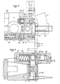
- the carriage 5 carries a block 19 rocking about a horizontal axis 20 and perpendicular to the direction of the tools in the magazine (axis X), under the action of a jack 21 carried by the carriage 5.
- the block 19 brought to in turn a sleeve 22 for tool holder; sleeve 22 slides in the block perpendicular to the axis 20.
- the sleeve 22 slides by the gusset 26 on a 25 carried by the block 19, the movements of the gusset 26 being limited downwards (exchange position) by the stop 24.
- the sleeve 22 has a possibility of oscillations of limited amplitude around the shaft 25; the sleeve 22 carries for this purpose pads 27 or bearings 28 constrained by springs 48 which slide on the flat face 29 of the block and maintain the surface 30 of the sleeve parallel to the surface 29.
- a fork 30 which when the carriage 5 is in position close to the magazine 3 comes to cooperate with the end of the rod of the jack 32, fixed relative to the magazine 3, to the frame 1 and slides 12 and 13.
- This connection with the end 31 of the jack 32 is made elastic in at least one direction by two springs 33 enclosing a diabolo 47.
- the jack 32 ensures the movements of withdrawal of a tool from the clamp 11 (or placement of a tool in the clamp) and in this position, the springs 33 take up the play of position of the clamp 9 along the axis X.
- the block 19 is held in the raised position by the tilt cylinder 21.
- the rear stop 34 sliding against the slide 35 fixed in relation slides 12 and 13 and the frame 1, maintains the sleeve 22 in the advanced position.
- the end of the slide 35, store side is positioned so that the sleeve 22 can move back to release the cone of the tool carried by the pliers 9 of the store.
- the recoil of the sleeve 22 is effected by the penetration of the fork 30 into the diablo 47 actuated by the jack 32.
- the tilting of the block 19 is not hampered by the presence of the slide 35.
- the cams 39, 40 are preferably flat faces cut from rotary shafts 41, 42 in the sleeve 22 and carrying the pinions 43, 44 on which the rack 45 acts. The latter is constantly pushed by the spring 46 towards the position of restraint. A cylinder 47 internal to the sleeve 22 ensures the release of the tool against the spring 46.
Landscapes
- Engineering & Computer Science (AREA)
- Mechanical Engineering (AREA)
- Automatic Tool Replacement In Machine Tools (AREA)
Claims (6)
Priority Applications (1)
| Application Number | Priority Date | Filing Date | Title |
|---|---|---|---|
| AT84401113T ATE20843T1 (de) | 1983-06-03 | 1984-05-30 | Werkzeugwechselvorrichtungen fuer werkzeugmaschinen. |
Applications Claiming Priority (2)
| Application Number | Priority Date | Filing Date | Title |
|---|---|---|---|
| FR8309244A FR2546794B1 (fr) | 1983-06-03 | 1983-06-03 | Perfectionnements aux dispositifs changeur d'outil pour machine-outil |
| FR8309244 | 1983-06-03 |
Publications (2)
| Publication Number | Publication Date |
|---|---|
| EP0128811A1 EP0128811A1 (de) | 1984-12-19 |
| EP0128811B1 true EP0128811B1 (de) | 1986-07-23 |
Family
ID=9289462
Family Applications (1)
| Application Number | Title | Priority Date | Filing Date |
|---|---|---|---|
| EP84401113A Expired EP0128811B1 (de) | 1983-06-03 | 1984-05-30 | Werkzeugwechselvorrichtungen für Werkzeugmaschinen |
Country Status (4)
| Country | Link |
|---|---|
| EP (1) | EP0128811B1 (de) |
| AT (1) | ATE20843T1 (de) |
| DE (1) | DE3460342D1 (de) |
| FR (1) | FR2546794B1 (de) |
Families Citing this family (4)
| Publication number | Priority date | Publication date | Assignee | Title |
|---|---|---|---|---|
| FR2564352B1 (fr) * | 1984-05-21 | 1988-10-21 | Vernier Sa | Dispositif de transfert et de stockage d'outils pour fraiseuses, centres d'usinage et machines analogues |
| FR2608487A1 (fr) * | 1986-04-09 | 1988-06-24 | Graffenstaden | Perfectionnements aux changeurs d'outil |
| JP2001062660A (ja) * | 1999-08-27 | 2001-03-13 | Mori Seiki Co Ltd | 工作機械の工具搬送装置 |
| DE102021131810A1 (de) * | 2021-12-02 | 2023-06-07 | Chiron Group Se | Werkzeugwechselvorrichtung, Werkzeugmaschine und Verfahren zum Wechseln eines Werkzeugs |
Family Cites Families (4)
| Publication number | Priority date | Publication date | Assignee | Title |
|---|---|---|---|---|
| US4196506A (en) * | 1976-09-07 | 1980-04-08 | Giddings & Lewis, Inc. | Tool changer machining center |
| JPS5839620B2 (ja) * | 1977-02-04 | 1983-08-31 | 株式会社山崎鉄工所 | ツ−ルシフタ− |
| FR2391809A1 (fr) * | 1977-05-25 | 1978-12-22 | Ratier Sa Forest | Centre d'usinage avec magasin a grand nombre d'outils |
| US4288909A (en) * | 1978-10-25 | 1981-09-15 | Kearney & Trecker Corporation | Automatic tool changer for machine tool |
-
1983
- 1983-06-03 FR FR8309244A patent/FR2546794B1/fr not_active Expired
-
1984
- 1984-05-30 EP EP84401113A patent/EP0128811B1/de not_active Expired
- 1984-05-30 DE DE8484401113T patent/DE3460342D1/de not_active Expired
- 1984-05-30 AT AT84401113T patent/ATE20843T1/de not_active IP Right Cessation
Also Published As
| Publication number | Publication date |
|---|---|
| ATE20843T1 (de) | 1986-08-15 |
| FR2546794A1 (fr) | 1984-12-07 |
| FR2546794B1 (fr) | 1986-05-23 |
| EP0128811A1 (de) | 1984-12-19 |
| DE3460342D1 (en) | 1986-08-28 |
Similar Documents
| Publication | Publication Date | Title |
|---|---|---|
| EP0068952B1 (de) | Werkzeugmaschinen mit hoher Produktivität | |
| EP0185286B1 (de) | Verfahren zum automatischen Beschicken von Bearbeitungsstationen und Vorrichtung zur Durchführung des Verfahrens | |
| EP0669185B1 (de) | Magazin zum Werkzeug- oder Werkstückwechseln bei Werkzeugmaschinen | |
| CH636543A5 (fr) | Machine-outil comprenant deux broches coaxiales opposees. | |
| FR2585276A2 (fr) | Machine executant diverses operations d'usinage telles que tournage, fraisage, alesage | |
| FR2609660A1 (fr) | Machine a meuler, notamment pour meuler des branches de ciseaux | |
| EP0032890A1 (de) | Werkzeugmaschinen von der Art eines Bearbeitungszentrums | |
| FR2488825A1 (fr) | Machine-outil avec changement rapide d'outil automatique | |
| EP0128811B1 (de) | Werkzeugwechselvorrichtungen für Werkzeugmaschinen | |
| EP0473747B1 (de) | Werkzeugmaschine, insbesondere für dekolletieren | |
| EP1231017A1 (de) | Hochpräzisionsübergabevorrichtung zum Absetzen von Gegenständen auf eine immobilisierte Palette | |
| CH659020A5 (fr) | Robot industriel. | |
| EP0416003B1 (de) | Revolver für werkzeugmaschinen | |
| EP0052023B1 (de) | Numerisch gesteuerte Werkzeugmaschine mit Werkzeugmagazin | |
| CH620630A5 (en) | Track for supporting and transporting components for a transfer machine | |
| CH673607A5 (en) | Multipurpose machine tool - with flexibility enhanced by using large number of its working axes | |
| EP1610926A1 (de) | Tisch zur vorbereitung eines werkstücks vor einer bearbeitung in einer nc-maschine | |
| FR2467052A1 (fr) | Dispositif de poste d'outils pour machine-outil | |
| FR2594735A1 (fr) | Appareil de transfert de pieces pour machines-outils | |
| EP0443019A1 (de) | Werkzeugwechsel-vorrichtung für werkzeugmaschinen | |
| EP0073687A1 (de) | Automatische Werkzeugwechselvorrichtung für eine Werkzeugmaschine | |
| FR2564352A1 (fr) | Dispositif de transfert et de stockage d'outils pour fraiseuses, centres d'usinage et machines analogues | |
| FR2527494A3 (fr) | Dispositif de changement d'outil pour centres de travail avec magasin d'outillage de grande capacite | |
| EP0329527A1 (de) | Zu- und Abführvorrichtung der Werkzeuge einer vertikalen Räummaschine | |
| FR2608487A1 (fr) | Perfectionnements aux changeurs d'outil |
Legal Events
| Date | Code | Title | Description |
|---|---|---|---|
| PUAI | Public reference made under article 153(3) epc to a published international application that has entered the european phase |
Free format text: ORIGINAL CODE: 0009012 |
|
| AK | Designated contracting states |
Designated state(s): AT BE CH DE FR GB IT LI LU NL SE |
|
| 17P | Request for examination filed |
Effective date: 19850109 |
|
| GRAA | (expected) grant |
Free format text: ORIGINAL CODE: 0009210 |
|
| RAP1 | Party data changed (applicant data changed or rights of an application transferred) |
Owner name: COMPAGNIE INTELAUTOMATISME |
|
| AK | Designated contracting states |
Kind code of ref document: B1 Designated state(s): AT BE CH DE FR GB IT LI LU NL SE |
|
| PG25 | Lapsed in a contracting state [announced via postgrant information from national office to epo] |
Ref country code: NL Effective date: 19860723 Ref country code: IT Free format text: LAPSE BECAUSE OF FAILURE TO SUBMIT A TRANSLATION OF THE DESCRIPTION OR TO PAY THE FEE WITHIN THE PRESCRIBED TIME-LIMIT;WARNING: LAPSES OF ITALIAN PATENTS WITH EFFECTIVE DATE BEFORE 2007 MAY HAVE OCCURRED AT ANY TIME BEFORE 2007. THE CORRECT EFFECTIVE DATE MAY BE DIFFERENT FROM THE ONE RECORDED. Effective date: 19860723 Ref country code: AT Effective date: 19860723 |
|
| REF | Corresponds to: |
Ref document number: 20843 Country of ref document: AT Date of ref document: 19860815 Kind code of ref document: T |
|
| PG25 | Lapsed in a contracting state [announced via postgrant information from national office to epo] |
Ref country code: SE Effective date: 19860731 |
|
| REF | Corresponds to: |
Ref document number: 3460342 Country of ref document: DE Date of ref document: 19860828 |
|
| NLV1 | Nl: lapsed or annulled due to failure to fulfill the requirements of art. 29p and 29m of the patents act | ||
| PLBE | No opposition filed within time limit |
Free format text: ORIGINAL CODE: 0009261 |
|
| PG25 | Lapsed in a contracting state [announced via postgrant information from national office to epo] |
Ref country code: LU Free format text: LAPSE BECAUSE OF NON-PAYMENT OF DUE FEES Effective date: 19870531 Ref country code: LI Effective date: 19870531 Ref country code: CH Effective date: 19870531 |
|
| 26N | No opposition filed | ||
| BERE | Be: lapsed |
Owner name: CIE INTELAUTOMATISME Effective date: 19870531 |
|
| REG | Reference to a national code |
Ref country code: CH Ref legal event code: PL |
|
| PG25 | Lapsed in a contracting state [announced via postgrant information from national office to epo] |
Ref country code: BE Effective date: 19890531 |
|
| PGFP | Annual fee paid to national office [announced via postgrant information from national office to epo] |
Ref country code: GB Payment date: 19920506 Year of fee payment: 9 |
|
| PGFP | Annual fee paid to national office [announced via postgrant information from national office to epo] |
Ref country code: DE Payment date: 19920521 Year of fee payment: 9 |
|
| PGFP | Annual fee paid to national office [announced via postgrant information from national office to epo] |
Ref country code: FR Payment date: 19920527 Year of fee payment: 9 |
|
| PG25 | Lapsed in a contracting state [announced via postgrant information from national office to epo] |
Ref country code: GB Effective date: 19930530 |
|
| GBPC | Gb: european patent ceased through non-payment of renewal fee |
Effective date: 19930530 |
|
| PG25 | Lapsed in a contracting state [announced via postgrant information from national office to epo] |
Ref country code: FR Effective date: 19940131 |
|
| PG25 | Lapsed in a contracting state [announced via postgrant information from national office to epo] |
Ref country code: DE Effective date: 19940201 |
|
| REG | Reference to a national code |
Ref country code: FR Ref legal event code: ST |