EP0416003B1 - Revolver für werkzeugmaschinen - Google Patents
Revolver für werkzeugmaschinen Download PDFInfo
- Publication number
- EP0416003B1 EP0416003B1 EP89906373A EP89906373A EP0416003B1 EP 0416003 B1 EP0416003 B1 EP 0416003B1 EP 89906373 A EP89906373 A EP 89906373A EP 89906373 A EP89906373 A EP 89906373A EP 0416003 B1 EP0416003 B1 EP 0416003B1
- Authority
- EP
- European Patent Office
- Prior art keywords
- turret
- piston
- revolving head
- head according
- rod
- Prior art date
- Legal status (The legal status is an assumption and is not a legal conclusion. Google has not performed a legal analysis and makes no representation as to the accuracy of the status listed.)
- Expired - Lifetime
Links
Images


Classifications
-
- B—PERFORMING OPERATIONS; TRANSPORTING
- B23—MACHINE TOOLS; METAL-WORKING NOT OTHERWISE PROVIDED FOR
- B23Q—DETAILS, COMPONENTS, OR ACCESSORIES FOR MACHINE TOOLS, e.g. ARRANGEMENTS FOR COPYING OR CONTROLLING; MACHINE TOOLS IN GENERAL CHARACTERISED BY THE CONSTRUCTION OF PARTICULAR DETAILS OR COMPONENTS; COMBINATIONS OR ASSOCIATIONS OF METAL-WORKING MACHINES, NOT DIRECTED TO A PARTICULAR RESULT
- B23Q16/00—Equipment for precise positioning of tool or work into particular locations not otherwise provided for
- B23Q16/02—Indexing equipment
- B23Q16/08—Indexing equipment having means for clamping the relatively movable parts together in the indexed position
- B23Q16/10—Rotary indexing
-
- B—PERFORMING OPERATIONS; TRANSPORTING
- B23—MACHINE TOOLS; METAL-WORKING NOT OTHERWISE PROVIDED FOR
- B23Q—DETAILS, COMPONENTS, OR ACCESSORIES FOR MACHINE TOOLS, e.g. ARRANGEMENTS FOR COPYING OR CONTROLLING; MACHINE TOOLS IN GENERAL CHARACTERISED BY THE CONSTRUCTION OF PARTICULAR DETAILS OR COMPONENTS; COMBINATIONS OR ASSOCIATIONS OF METAL-WORKING MACHINES, NOT DIRECTED TO A PARTICULAR RESULT
- B23Q1/00—Members which are comprised in the general build-up of a form of machine, particularly relatively large fixed members
- B23Q1/25—Movable or adjustable work or tool supports
- B23Q1/44—Movable or adjustable work or tool supports using particular mechanisms
- B23Q1/50—Movable or adjustable work or tool supports using particular mechanisms with rotating pairs only, the rotating pairs being the first two elements of the mechanism
- B23Q1/54—Movable or adjustable work or tool supports using particular mechanisms with rotating pairs only, the rotating pairs being the first two elements of the mechanism two rotating pairs only
-
- B—PERFORMING OPERATIONS; TRANSPORTING
- B23—MACHINE TOOLS; METAL-WORKING NOT OTHERWISE PROVIDED FOR
- B23Q—DETAILS, COMPONENTS, OR ACCESSORIES FOR MACHINE TOOLS, e.g. ARRANGEMENTS FOR COPYING OR CONTROLLING; MACHINE TOOLS IN GENERAL CHARACTERISED BY THE CONSTRUCTION OF PARTICULAR DETAILS OR COMPONENTS; COMBINATIONS OR ASSOCIATIONS OF METAL-WORKING MACHINES, NOT DIRECTED TO A PARTICULAR RESULT
- B23Q2220/00—Machine tool components
- B23Q2220/002—Tool turrets
-
- Y—GENERAL TAGGING OF NEW TECHNOLOGICAL DEVELOPMENTS; GENERAL TAGGING OF CROSS-SECTIONAL TECHNOLOGIES SPANNING OVER SEVERAL SECTIONS OF THE IPC; TECHNICAL SUBJECTS COVERED BY FORMER USPC CROSS-REFERENCE ART COLLECTIONS [XRACs] AND DIGESTS
- Y10—TECHNICAL SUBJECTS COVERED BY FORMER USPC
- Y10T—TECHNICAL SUBJECTS COVERED BY FORMER US CLASSIFICATION
- Y10T29/00—Metal working
- Y10T29/51—Plural diverse manufacturing apparatus including means for metal shaping or assembling
- Y10T29/5152—Plural diverse manufacturing apparatus including means for metal shaping or assembling with turret mechanism
- Y10T29/5154—Plural diverse manufacturing apparatus including means for metal shaping or assembling with turret mechanism tool turret
- Y10T29/5155—Rotary tool holder
-
- Y—GENERAL TAGGING OF NEW TECHNOLOGICAL DEVELOPMENTS; GENERAL TAGGING OF CROSS-SECTIONAL TECHNOLOGIES SPANNING OVER SEVERAL SECTIONS OF THE IPC; TECHNICAL SUBJECTS COVERED BY FORMER USPC CROSS-REFERENCE ART COLLECTIONS [XRACs] AND DIGESTS
- Y10—TECHNICAL SUBJECTS COVERED BY FORMER USPC
- Y10T—TECHNICAL SUBJECTS COVERED BY FORMER US CLASSIFICATION
- Y10T408/00—Cutting by use of rotating axially moving tool
- Y10T408/36—Machine including plural tools
- Y10T408/37—Turret of tools
-
- Y—GENERAL TAGGING OF NEW TECHNOLOGICAL DEVELOPMENTS; GENERAL TAGGING OF CROSS-SECTIONAL TECHNOLOGIES SPANNING OVER SEVERAL SECTIONS OF THE IPC; TECHNICAL SUBJECTS COVERED BY FORMER USPC CROSS-REFERENCE ART COLLECTIONS [XRACs] AND DIGESTS
- Y10—TECHNICAL SUBJECTS COVERED BY FORMER USPC
- Y10T—TECHNICAL SUBJECTS COVERED BY FORMER US CLASSIFICATION
- Y10T409/00—Gear cutting, milling, or planing
- Y10T409/30—Milling
- Y10T409/30784—Milling including means to adustably position cutter
- Y10T409/307952—Linear adjustment
- Y10T409/308232—Linear adjustment and angular adjustment
-
- Y—GENERAL TAGGING OF NEW TECHNOLOGICAL DEVELOPMENTS; GENERAL TAGGING OF CROSS-SECTIONAL TECHNOLOGIES SPANNING OVER SEVERAL SECTIONS OF THE IPC; TECHNICAL SUBJECTS COVERED BY FORMER USPC CROSS-REFERENCE ART COLLECTIONS [XRACs] AND DIGESTS
- Y10—TECHNICAL SUBJECTS COVERED BY FORMER USPC
- Y10T—TECHNICAL SUBJECTS COVERED BY FORMER US CLASSIFICATION
- Y10T74/00—Machine element or mechanism
- Y10T74/14—Rotary member or shaft indexing, e.g., tool or work turret
- Y10T74/1476—Rotary member or shaft indexing, e.g., tool or work turret with means to axially shift shaft
Definitions
- the present invention relates to a turret head for a machine tool comprising a fixed frame, a spindle turret movable in rotation relative to this frame, at least two tool spindles mounted on said turret, means for driving said rotations pins comprising a drive shaft and means for automatically controlling the movement of said turret, in which the turret comprises a first element integral with said frame and a second element movable relative to the first element, in which said automatic control means comprise axial piston and a rotary piston for displacing said second element of the turret respectively axially and in rotation relative to said first element, and in which the axis of the drive shaft forms an angle of 45 ° with the axis of the turret.
- French patent application FR-A-2 526 343 describes an automatic multi-spindle revolver comprising a spindle holder having the characteristics of the preamble of main claim 1 with the exception of the automatic turret movement control means.
- the present invention proposes to overcome these drawbacks by offering a revolver head of the type mentioned above, characterized in that the axial piston comprises a rod secured to the first element of the turret and said fixed frame, and a body comprising a cap secured of said second element of the turret, and movable axially and in rotation relative to said rod, and in that it comprises a compression spring member mounted between the base of the piston and the second element of the turret, this spring member being arranged to bring said second element into abutment against said first element of the turret after a relative axial movement of these two elements.
- the compression spring member is preferably mounted partly in a first annular cavity formed at the base of the piston and partly in a second annular cavity formed in said second element of the turret, these two annular cavities being arranged coaxially with respect to to said rod in the extension of one another. It is advantageously constituted by a stack of Belleville washers.
- the rotary piston is mounted at the end of the rod and is housed inside a chamber of cylindrical shape.
- the axial piston may comprise at least one recess, said second element of the turret carrying at least one pin arranged to be housed in said recess, and these two components being arranged to make integral said axial piston, itself solid with the rod, said second element of the turret when the latter is offset axially relative to said first element.
- the spindle drive means preferably comprise a toothed drive pinion integral with a drive shaft, this toothed pinion comprising a cylindrical part and a frustoconical part, and a drive pinion integral with a drive shaft. drive of a spindle which is always engaged at least with the frustoconical part of the drive pinion of the drive shaft.
- the generatrices of said frustoconical part form an angle of 45 ° with the axis of the wheel, and are parallel with the axis of the rod.
- the frustoconical part and the cylindrical part of the drive pinion are advantageously pressed one against the other by a spring member to be coupled.
- This spring member is preferably constituted by a stack of washers from 'Belleville.
- the turret head comprises a multicontactor housed in a cavity formed in the frame, this multicontactor being arranged to control the electrical functions of this head, and at least two control rods corresponding respectively to said tool-holder pins , and associated with control pins corresponding respectively to each of the pins and arranged to actuate said multicontactor via one of said control rods.
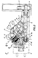
- the revolver head for machine tool 10 shown essentially comprises a fixed frame 11 on which is adapted a turret 12 spindle holder which, as the name suggests, carries for example three spindles tool holder 13 arranged at 120 ° one of the other.
- the pins 13 could be replaced by adaptations 14 of the multispindle type known per se. It is understood that the number of spindles or multispindle adaptations is not limited to three, although this construction is advantageous in certain cases for reasons of space.
- the fixed frame 11 bent at 90 °, essentially contains the drive shaft 15 carrying at its end remote from the turret a wheel or a pinion d drive 16 over which a belt 17 passes and at its other end a drive pinion 18 which can mesh with a drive pinion 19 secured to the tool holder head 20 of the spindle 13.
- the turret 12 is disposed relative to the frame, so that its axis forms with the angle of the drive shaft 15, an angle of 45 °.
- This particularly advantageous arrangement allows optimal disengagement of the spindles or multi-spindles relative to that which is in the machining position and which is parallel to the drive shaft.
- machining forces are ideally absorbed, which is not the case with the other known spindles which undergo an overturning torque when they are in the machining position.
- the turret 12 can move relative to the fixed frame 11 according to an axial movement illustrated by the double arrow A and according to a rotary movement illustrated by the double arrow B.
- the turret consists of two elements respectively 21 and 22, the first 21 of which is integral with the fixed frame and the second 22 of which, in the form of a cover, partially fits onto said first element.
- the first element 21, which is rigidly fixed to the fixed frame 11, carries a sleeve or fur 23 inside which can rotate around its axis a cylindrical rod 24 at the upper end of which is fixed an axial piston 25, of which the role will be explained later.
- the piston 25 is housed in a chamber formed inside a cap 26 of substantially shaped cylindrical, which is fixed to the second element 22 of the turret by means of screws or bolts 27.
- a compression spring 28, preferably composed of a stack of Belleville washers, is partially housed in a first annular cavity formed at the base of the piston 25, coaxial with respect to the rod 24, and partially in a second annular cavity extending the previous one and formed in the second element 22 of the turret coaxially with respect to this same rod 24.
- the fixed frame 11 is equipped with a duct 29 comprising a mouth 30 and a linear tube 31 which opens into an axial duct 32 formed through the rod 24 and the piston 25 to open into a pressure chamber 33 formed between the piston 25 and the inner wall of the cap 26.
- the pressure of the hydraulic fluid which is transmitted by the conduits 31 and 32 manifests itself in the chamber 33, which has the effect of displacing the cap 26 relative to the piston 25.
- the cap 26 is made integral with the second element 22 of the turret by the bolts 27, this second element is raised relative to the first element 21 by compressing the spring 28, due to the crushing of the Belleville washers of which it is made up.
- the second element 22 of the turret is also equipped with at least one pin or bolt 34, the head of which penetrates into a cavity 35 formed at the base of the axial piston 25 and the aim of which is to make said second momentarily integral element of the turret and said piston. In this position, the piston can serve as a driving element intended to drive the turret in rotation according to a movement which will be described in more detail below.
- the rod 24, which is integral with the piston 25, carries at its lower end a rotary piston 36 housed in a cylindrical chamber 37 formed in the first element 21 of the turret.
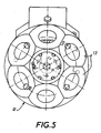
- This rotary piston can, as shown more particularly in FIG. 3, be brought into abutment in two different positions respectively 36a and 36b, depending on whether hydraulic fluid is injected on one side or the other of this piston rotary in the chamber 37. Since the rotary piston 36 is integral with the piston 25, by means of the rod 24 and that the latter is temporarily made integral, by at least one pin 34, with the second element 22 of the turret , the latter can rotate by an angle of 120 ° to swap the pins.
- the cap 26 When the pressure is released in the pressure chamber 33, the cap 26 returns to its initial position, pushed by the spring 28, which releases the head of the pin or pins 34 from the corresponding recess 35 and separates the piston 25 of the second element 22 of the turret.
- the rotary piston 36 By an appropriate injection of pressurized fluid, the rotary piston 36 is returned to its initial position, which makes it ready for a new working cycle allowing the turret, or more precisely the second part 22 of the turret, to rotate, d 'An angle of 120 ° (in the case where the turret carries three tool-holder spindles) relative to the first part 21 of this turret or of the fixed frame.
- the drive pinion 18 of the spindle drive means comprises a first cylindrical part 18a and a second frustoconical part 18b formed at the front end of this member.
- the cylindrical part meshes with the drive pinion 19.
- the pinion 19 remains engaged with the pinion 18 thanks to the existence of the frustoconical part 18b whose angle is 45 °.
- This embodiment ensures precise indexing of the drive wheels.
- the frustoconical part 18b is in abutment against the cylindrical part 18a by means of a compression spring 42 constituted by stacked Belleville washers.
- the purpose of the spring is to absorb the momentary stresses which can be exerted on the teeth if, during a change of spindle, the teeth of the pinion 19 fall in front of the teeth of the pinion 18, and thus to avoid a blocking of drive, or even damage to the sprockets.
- indexing pins 38 disposed between two corresponding surfaces of the first and second elements of the turret, allow this second element 22 to be indexed in a precise manner relative to the first element of this turret .
- the pins are six in number and are offset by 60 °. These pins could also be replaced by elements in relief from one of the elements engaging in cavities complementary to the other element.
- a multicontactor 39 ensures the electrical controls of the device.
- This multicontactor is housed in a cavity formed in the frame. It is associated with at least two control rods 40 corresponding respectively to said tool-holder pins, each of which carries for example a control pin 41 which is intended to act on one of the control rods 40 to actuate one of the contacts of the multicontactor .
- Figures 4 and 5 illustrate a variant in which the turret 12 of the turret head 10 carries six tool-holder spindles 13 which are mounted at 60 ° from one another. As before, these pins could be replaced by multi-pin adapter elements.
- the construction of this embodiment is based on the same principles as those which are used for the realization of the revolver head according to the preceding figures.
- the angle of rotation of the head to go from one spindle to another is 60 °.
- the presence of six spindles increases the flexibility of the machine and increases its capacities.
- the spindle drive mechanism remains similar to that described above.
Landscapes
- Engineering & Computer Science (AREA)
- Mechanical Engineering (AREA)
- Automatic Tool Replacement In Machine Tools (AREA)
- Fluid-Damping Devices (AREA)
- Machine Tool Units (AREA)
- Machine Tool Positioning Apparatuses (AREA)
- Cutting Tools, Boring Holders, And Turrets (AREA)
- Details Of Spanners, Wrenches, And Screw Drivers And Accessories (AREA)
Claims (10)
- Revolver für Werkzeugmaschinen, bestehend aus einem festen Gestell, einem sich im Verhältnis zu diesem Gestell drehenden, mobilen Meißelhalter, mindestens zwei auf dem besagten Meißelhalter angeordneten Werkzeugträgerspindeln, Drehantriebsmitteln der besagten Spindeln mit einer Antriebswelle (15) und Steuermitteln zum automatischen Verfahren des besagten Meißelhalters, wobei der Meißelhalter (12) ein erstes Element (21) aufweist, das mit dem besagten Gestell (11) schlüssig ist, sowie ein zweites, im Verhältnis zum Ersten mobiles Element (22), wobei die besagten Automatiksteuermittel einen Axialkolben (25) und einen Drehkolben (36) aufweisen, um jeweils das besagte zweite Element (22) des Meißelhalters (12) im Verhältnis zum besagten ersten Element (21) in axialer und in Drehrichtung zu verschieben, wobei die Achse der Antriebswelle (15) mit der Achse des Meißelhalters (12) einen Winkel von 45° bildet, dadurch gekennzeichnet, daß der Axialkolben über eine mit dem ersten Element (21) des Meißelhalters und des besagten festen Gestells (11) schlüssige Stange (24) verfügt, sowie über einen Körper mit einem Verschluß (26), der mit dem besagten zweiten Element (22) des Meißelhalters schlüssig und im Verhältnis zur besagten Stange in axialer und Drehrichtung mobil ist, und daß er ein Druckfederorgan (28) aufweist, daß zwischen der Kolbenbasis (25) und dem besagten zweiten Element (22) des Meißelhalters angeordnet ist, wobei dieses Federorgan so ausgelegt ist, daß es das besagte zweite Element (22) gegen das besagte erste Element (21) des Meißelhalters drückt, nach einer relativen Axialverschiebung dieser beiden Elemente.
- Revolver gemäß Anspruch 1, dadurch gekennzeichnet, daß das besagte Druckfederorgan (28) teilweise in einer ersten ringförmigen Vertiefung an der Basis des Kolbens (25) angeordnet ist, und teilweise in einer zweiten ringförmigen Vertiefung im besagten zweiten Element (22) des Meißelhalters (12), wobei diese beiden ringförmigen Vertiefungen im Verhältnis zur besagten Stange (24) koaxial verlaufen, innerhalb ihrer jeweiligen Verlängerung.
- Revolver gemäß Anspruch 4, dadurch gekennzeichnet, daß das Druckfederorgan (28) aus einem Stapel von Belleville-Dichtungsringen besteht.
- Revolver gemäß Anspruch 1, dadurch gekennzeichnet, daß der Drehkolben (36) am Ende der Stange (24) angeordnet ist und sich innerhalb einer zylinderförmigen Kammer (37) befindet.
- Revolver gemäß Anspruch 1, dadurch gekennzeichnet, daß der Axialkolben (25) mindestens eine Vertiefung (35) und das besagte zweite Element (22) des Meißelhalters mindestens einen Stift (34) aufweisen, der sich in die besagte(n) Vertiefung(en) (35) einfügt, wobei diese beiden Bestandteile angeordnet sind, um den besagten Axialkolben (25) schlüssig zu machen, der seinerseits mit der Stange (24) des besagten zweiten Elements (22) des Meißelhalters schlüssig ist, wenn er im Verhältnis zum besagten ersten Element (21) axial verschoben ist.
- Revolver gemäß Anspruch 1, dadurch gekennzeichnet, daß die Ahtriebsmittel der Spindeln ein mit der Antriebswelle (15) schlüssiges Zahnantriebsritzel (18) aufweisen, wobei dieses Zahnritzel ein zylinderförmiges Teil (18a) und ein kegelstumpfartigen Teil (18b) aufweist, sowie ein mit einer Antriebswelle einer Spindel (20) schlüssiges Zahnantriebsritzel (19), die immer mit zumindest dem kegelstumpfartigen Teil des Antriebsritzels der Antriebswelle in Verbindung steht.
- Revolver gemäß Anspruch 6, dadurch gekennzeichnet, daß die Erzeugenden des besagten kegelstumpfartigen Teils (18b) mit der Achse des Ritzels einen Winkel von 45° bilden und parallel zur Stangenachse (24) verlaufen.
- Revolver gemäß Anspruch 6, dadurch gekennzeichnet, daß das kegelstumpfartige Teil (18b) und das zylinderförmige Teil (18a) des Antriebsritzels von einem Federorgan (42) gegeneinander gedrückt werden, um gekoppelt zu werden.
- Revolver gemäß Anspruch 8, dadurch gekennzeichnet, daß das Federorgan (42) aus einem Stapel von Belleville-Dichtungsringen besteht.
- Revolver gemaß Anspruch 1, dadurch gekennzeichnet, daß er einen Mehrfachschütz (39) umfaßt, der in einer im Gestell vorgesehenen Vertiefung angeordnet ist, wobei dieses Mehrfachschütz zur Steuerung der elektrischen Funktionen dieses Revolvers ausgelegt ist, sowie von mindestens zwei Steuerstangen (40), die jeweils den besagten Meißelhaltern zugeordnet sind und mit Steuerstiften (41) in Verbindung stehen, die jeweils einer der Spindeln zugeordnet und so angeordnet sind, daß sie das besagte Mehrfachschütz (39) über eine der besagten Steuerstangen betätigen.
Priority Applications (1)
| Application Number | Priority Date | Filing Date | Title |
|---|---|---|---|
| AT89906373T ATE92821T1 (de) | 1988-05-25 | 1989-05-24 | Revolver fuer werkzeugmaschinen. |
Applications Claiming Priority (2)
| Application Number | Priority Date | Filing Date | Title |
|---|---|---|---|
| FR8807142 | 1988-05-25 | ||
| FR8807142A FR2631872A1 (fr) | 1988-05-25 | 1988-05-25 | Tete revolver pour machine-outil |
Publications (2)
| Publication Number | Publication Date |
|---|---|
| EP0416003A1 EP0416003A1 (de) | 1991-03-13 |
| EP0416003B1 true EP0416003B1 (de) | 1993-08-11 |
Family
ID=9366716
Family Applications (1)
| Application Number | Title | Priority Date | Filing Date |
|---|---|---|---|
| EP89906373A Expired - Lifetime EP0416003B1 (de) | 1988-05-25 | 1989-05-24 | Revolver für werkzeugmaschinen |
Country Status (7)
| Country | Link |
|---|---|
| US (1) | US5146663A (de) |
| EP (1) | EP0416003B1 (de) |
| JP (1) | JPH03504471A (de) |
| DE (1) | DE68908410T2 (de) |
| ES (1) | ES1010415Y (de) |
| FR (1) | FR2631872A1 (de) |
| WO (1) | WO1989011376A1 (de) |
Families Citing this family (8)
| Publication number | Priority date | Publication date | Assignee | Title |
|---|---|---|---|---|
| GB2273067B (en) * | 1992-11-24 | 1996-04-10 | Honda Motor Co Ltd | Turret machine tool |
| IT1268332B1 (it) * | 1994-09-16 | 1997-02-27 | Sasib Spa | Dispositivo manipolatore per la movimentazione, in particolare per l'orientamento di pezzi, utensili, o simili. |
| IT1283209B1 (it) * | 1996-03-08 | 1998-04-16 | Riello Macchine Utensili Spa | Dispositivo di cambio di utensile per unita' operatrici di macchine utensili |
| DE19618757C2 (de) * | 1996-05-09 | 2001-02-22 | Witzig & Frank Turmatic Gmbh | Werkzeugmaschine |
| US6785943B2 (en) | 1998-09-04 | 2004-09-07 | Hardinge, Inc. | Indexing tool turret |
| US6442815B1 (en) | 2000-04-18 | 2002-09-03 | The Regents Of The University Of Michigan | Reconfigurable automatic tool changer |
| FR2856945B1 (fr) * | 2003-07-02 | 2005-11-25 | Ind Automation | Machine d'assemblage |
| US7509720B2 (en) * | 2007-11-05 | 2009-03-31 | Wawrzyniak Walter W | Continuous tool rotation tool turret |
Family Cites Families (10)
| Publication number | Priority date | Publication date | Assignee | Title |
|---|---|---|---|---|
| US2915922A (en) * | 1955-09-07 | 1959-12-08 | Warner Swasey Co | Indexible tool holder |
| NL236924A (de) * | 1958-03-10 | |||
| GB1025019A (en) * | 1964-05-18 | 1966-04-06 | Cincinnati Milling Machine Co | Lathe |
| FR2055944A5 (de) * | 1969-08-08 | 1971-05-14 | Berthiez C N M P | |
| GB1310931A (en) * | 1970-02-03 | 1973-03-21 | Autologic Ltd | Machine tools |
| FR2243757B1 (de) * | 1973-09-15 | 1978-11-24 | Sauter Kg Feinmechanik | |
| DE2739087A1 (de) * | 1976-08-30 | 1978-03-09 | Komatsu Mfg Co Ltd | Werkzeugmaschine |
| DE3216892A1 (de) * | 1982-05-06 | 1983-11-10 | Index-Werke Kg Hahn & Tessky, 7300 Esslingen | Mehrspindel-revolverdrehautomat |
| JPS6347003A (ja) * | 1986-08-12 | 1988-02-27 | Howa Mach Ltd | タレツトユニツト |
| US4887345A (en) * | 1986-10-09 | 1989-12-19 | Kabushiki Kaisha Sankyo Seiki Seisakusho and Toto, Ltd. | Turret apparatus |
-
1988
- 1988-05-25 FR FR8807142A patent/FR2631872A1/fr active Pending
-
1989
- 1989-05-24 EP EP89906373A patent/EP0416003B1/de not_active Expired - Lifetime
- 1989-05-24 JP JP1506153A patent/JPH03504471A/ja active Pending
- 1989-05-24 WO PCT/FR1989/000247 patent/WO1989011376A1/fr active IP Right Grant
- 1989-05-24 DE DE89906373T patent/DE68908410T2/de not_active Expired - Fee Related
- 1989-05-24 ES ES8901676U patent/ES1010415Y/es not_active Expired - Fee Related
- 1989-05-24 US US07/613,623 patent/US5146663A/en not_active Expired - Fee Related
Also Published As
| Publication number | Publication date |
|---|---|
| EP0416003A1 (de) | 1991-03-13 |
| WO1989011376A1 (fr) | 1989-11-30 |
| JPH03504471A (ja) | 1991-10-03 |
| DE68908410D1 (de) | 1993-09-16 |
| ES1010415U (es) | 1990-01-01 |
| US5146663A (en) | 1992-09-15 |
| FR2631872A1 (fr) | 1989-12-01 |
| ES1010415Y (es) | 1990-06-16 |
| DE68908410T2 (de) | 1994-02-17 |
Similar Documents
| Publication | Publication Date | Title |
|---|---|---|
| EP0416003B1 (de) | Revolver für werkzeugmaschinen | |
| EP0954412A1 (de) | Stiftfoermiges werkzeug zum zentrieren und spannen | |
| FR2512367A1 (fr) | Tourelle porte-outils | |
| FR2700486A1 (fr) | Tête d'actionnement indexée pour machines-outils automatiques. | |
| EP3209458B1 (de) | Verbesserte vibrationsbearbeitungsvorrichtung | |
| EP0214090A1 (de) | Vorrichtung zum Antreiben von Werkzeugträgern in einer Werkzeugmaschine | |
| EP0418145A1 (de) | Andruckelement zum Aufspannen von Werkstücken | |
| EP1238737B1 (de) | Gewindeschneideinheit | |
| EP0245177A1 (de) | Vorrichtung zum Stützen eines Werkstückes zur Ermöglichung der Bearbeitung auf seiner fünften Fläche | |
| EP3307462B1 (de) | Drehmaschine und führungsbuchse | |
| EP0192586A1 (de) | Automatische Gewindeschneidvorrichtung | |
| FR2657281A1 (fr) | Machine pour tailler des engrenages. | |
| EP1680258A2 (de) | Dem werkzeug einer schneidwerkzeugmaschine zugeordnete saugvorrichtung | |
| FR2704789A1 (fr) | Tête révolver multibroche pour machine-outil. | |
| EP0128811B1 (de) | Werkzeugwechselvorrichtungen für Werkzeugmaschinen | |
| EP0154584B1 (de) | Selbsttätige Nachstellvorrichtung für eine Kupplung | |
| FR2467052A1 (fr) | Dispositif de poste d'outils pour machine-outil | |
| EP0074452A1 (de) | Kupplungseinheit für Fräserkopf | |
| EP0443019A1 (de) | Werkzeugwechsel-vorrichtung für werkzeugmaschinen | |
| EP0098409A1 (de) | Vorrichtung zum Antrieb eines schwingenden Verteilrohrs | |
| EP4084922B1 (de) | Elektrospindel mit integriertem vortrieb mit automatischem werkzeughalterwechsel | |
| FR2543866A1 (fr) | Dispositif de blocage et de deblocage automatiques d'un outil dans une broche rotative de machine-outil | |
| FR2800650A1 (fr) | Machine a former des extremites de tubes | |
| FR2688435A1 (fr) | Dispositif de taraudage sur presse. | |
| FR2756205A1 (fr) | Changeur d'outils pour robots et analogues |
Legal Events
| Date | Code | Title | Description |
|---|---|---|---|
| PUAI | Public reference made under article 153(3) epc to a published international application that has entered the european phase |
Free format text: ORIGINAL CODE: 0009012 |
|
| 17P | Request for examination filed |
Effective date: 19901113 |
|
| AK | Designated contracting states |
Kind code of ref document: A1 Designated state(s): AT BE CH DE FR GB IT LI LU NL SE |
|
| 17Q | First examination report despatched |
Effective date: 19920406 |
|
| RAP1 | Party data changed (applicant data changed or rights of an application transferred) |
Owner name: SOMEX MULHOUSE S.A. |
|
| GRAA | (expected) grant |
Free format text: ORIGINAL CODE: 0009210 |
|
| AK | Designated contracting states |
Kind code of ref document: B1 Designated state(s): AT BE CH DE FR GB IT LI LU NL SE |
|
| PG25 | Lapsed in a contracting state [announced via postgrant information from national office to epo] |
Ref country code: SE Effective date: 19930811 Ref country code: NL Effective date: 19930811 Ref country code: GB Effective date: 19930811 Ref country code: AT Effective date: 19930811 |
|
| REF | Corresponds to: |
Ref document number: 92821 Country of ref document: AT Date of ref document: 19930815 Kind code of ref document: T |
|
| REF | Corresponds to: |
Ref document number: 68908410 Country of ref document: DE Date of ref document: 19930916 |
|
| ITF | It: translation for a ep patent filed |
Owner name: DOTT. FRANCO CICOGNA |
|
| NLV1 | Nl: lapsed or annulled due to failure to fulfill the requirements of art. 29p and 29m of the patents act | ||
| GBV | Gb: ep patent (uk) treated as always having been void in accordance with gb section 77(7)/1977 [no translation filed] |
Effective date: 19930811 |
|
| PG25 | Lapsed in a contracting state [announced via postgrant information from national office to epo] |
Ref country code: LU Free format text: LAPSE BECAUSE OF NON-PAYMENT OF DUE FEES Effective date: 19940531 Ref country code: BE Effective date: 19940531 |
|
| PLBE | No opposition filed within time limit |
Free format text: ORIGINAL CODE: 0009261 |
|
| STAA | Information on the status of an ep patent application or granted ep patent |
Free format text: STATUS: NO OPPOSITION FILED WITHIN TIME LIMIT |
|
| 26N | No opposition filed | ||
| BERE | Be: lapsed |
Owner name: S.A. SOMEX MULHOUSE Effective date: 19940531 |
|
| PGFP | Annual fee paid to national office [announced via postgrant information from national office to epo] |
Ref country code: DE Payment date: 19950527 Year of fee payment: 7 |
|
| PGFP | Annual fee paid to national office [announced via postgrant information from national office to epo] |
Ref country code: FR Payment date: 19950531 Year of fee payment: 7 |
|
| PGFP | Annual fee paid to national office [announced via postgrant information from national office to epo] |
Ref country code: CH Payment date: 19950712 Year of fee payment: 7 |
|
| PG25 | Lapsed in a contracting state [announced via postgrant information from national office to epo] |
Ref country code: LI Effective date: 19960531 Ref country code: CH Effective date: 19960531 |
|
| REG | Reference to a national code |
Ref country code: CH Ref legal event code: PL |
|
| PG25 | Lapsed in a contracting state [announced via postgrant information from national office to epo] |
Ref country code: FR Effective date: 19970131 |
|
| PG25 | Lapsed in a contracting state [announced via postgrant information from national office to epo] |
Ref country code: DE Effective date: 19970201 |
|
| REG | Reference to a national code |
Ref country code: FR Ref legal event code: ST |
|
| PG25 | Lapsed in a contracting state [announced via postgrant information from national office to epo] |
Ref country code: IT Free format text: LAPSE BECAUSE OF NON-PAYMENT OF DUE FEES;WARNING: LAPSES OF ITALIAN PATENTS WITH EFFECTIVE DATE BEFORE 2007 MAY HAVE OCCURRED AT ANY TIME BEFORE 2007. THE CORRECT EFFECTIVE DATE MAY BE DIFFERENT FROM THE ONE RECORDED. Effective date: 20050524 |