EP0416003B1 - Revolving head for machine tool - Google Patents
Revolving head for machine tool Download PDFInfo
- Publication number
- EP0416003B1 EP0416003B1 EP89906373A EP89906373A EP0416003B1 EP 0416003 B1 EP0416003 B1 EP 0416003B1 EP 89906373 A EP89906373 A EP 89906373A EP 89906373 A EP89906373 A EP 89906373A EP 0416003 B1 EP0416003 B1 EP 0416003B1
- Authority
- EP
- European Patent Office
- Prior art keywords
- turret
- piston
- revolving head
- head according
- rod
- Prior art date
- Legal status (The legal status is an assumption and is not a legal conclusion. Google has not performed a legal analysis and makes no representation as to the accuracy of the status listed.)
- Expired - Lifetime
Links
Images


Classifications
-
- B—PERFORMING OPERATIONS; TRANSPORTING
- B23—MACHINE TOOLS; METAL-WORKING NOT OTHERWISE PROVIDED FOR
- B23Q—DETAILS, COMPONENTS, OR ACCESSORIES FOR MACHINE TOOLS, e.g. ARRANGEMENTS FOR COPYING OR CONTROLLING; MACHINE TOOLS IN GENERAL CHARACTERISED BY THE CONSTRUCTION OF PARTICULAR DETAILS OR COMPONENTS; COMBINATIONS OR ASSOCIATIONS OF METAL-WORKING MACHINES, NOT DIRECTED TO A PARTICULAR RESULT
- B23Q16/00—Equipment for precise positioning of tool or work into particular locations not otherwise provided for
- B23Q16/02—Indexing equipment
- B23Q16/08—Indexing equipment having means for clamping the relatively movable parts together in the indexed position
- B23Q16/10—Rotary indexing
-
- B—PERFORMING OPERATIONS; TRANSPORTING
- B23—MACHINE TOOLS; METAL-WORKING NOT OTHERWISE PROVIDED FOR
- B23Q—DETAILS, COMPONENTS, OR ACCESSORIES FOR MACHINE TOOLS, e.g. ARRANGEMENTS FOR COPYING OR CONTROLLING; MACHINE TOOLS IN GENERAL CHARACTERISED BY THE CONSTRUCTION OF PARTICULAR DETAILS OR COMPONENTS; COMBINATIONS OR ASSOCIATIONS OF METAL-WORKING MACHINES, NOT DIRECTED TO A PARTICULAR RESULT
- B23Q1/00—Members which are comprised in the general build-up of a form of machine, particularly relatively large fixed members
- B23Q1/25—Movable or adjustable work or tool supports
- B23Q1/44—Movable or adjustable work or tool supports using particular mechanisms
- B23Q1/50—Movable or adjustable work or tool supports using particular mechanisms with rotating pairs only, the rotating pairs being the first two elements of the mechanism
- B23Q1/54—Movable or adjustable work or tool supports using particular mechanisms with rotating pairs only, the rotating pairs being the first two elements of the mechanism two rotating pairs only
-
- B—PERFORMING OPERATIONS; TRANSPORTING
- B23—MACHINE TOOLS; METAL-WORKING NOT OTHERWISE PROVIDED FOR
- B23Q—DETAILS, COMPONENTS, OR ACCESSORIES FOR MACHINE TOOLS, e.g. ARRANGEMENTS FOR COPYING OR CONTROLLING; MACHINE TOOLS IN GENERAL CHARACTERISED BY THE CONSTRUCTION OF PARTICULAR DETAILS OR COMPONENTS; COMBINATIONS OR ASSOCIATIONS OF METAL-WORKING MACHINES, NOT DIRECTED TO A PARTICULAR RESULT
- B23Q2220/00—Machine tool components
- B23Q2220/002—Tool turrets
-
- Y—GENERAL TAGGING OF NEW TECHNOLOGICAL DEVELOPMENTS; GENERAL TAGGING OF CROSS-SECTIONAL TECHNOLOGIES SPANNING OVER SEVERAL SECTIONS OF THE IPC; TECHNICAL SUBJECTS COVERED BY FORMER USPC CROSS-REFERENCE ART COLLECTIONS [XRACs] AND DIGESTS
- Y10—TECHNICAL SUBJECTS COVERED BY FORMER USPC
- Y10T—TECHNICAL SUBJECTS COVERED BY FORMER US CLASSIFICATION
- Y10T29/00—Metal working
- Y10T29/51—Plural diverse manufacturing apparatus including means for metal shaping or assembling
- Y10T29/5152—Plural diverse manufacturing apparatus including means for metal shaping or assembling with turret mechanism
- Y10T29/5154—Plural diverse manufacturing apparatus including means for metal shaping or assembling with turret mechanism tool turret
- Y10T29/5155—Rotary tool holder
-
- Y—GENERAL TAGGING OF NEW TECHNOLOGICAL DEVELOPMENTS; GENERAL TAGGING OF CROSS-SECTIONAL TECHNOLOGIES SPANNING OVER SEVERAL SECTIONS OF THE IPC; TECHNICAL SUBJECTS COVERED BY FORMER USPC CROSS-REFERENCE ART COLLECTIONS [XRACs] AND DIGESTS
- Y10—TECHNICAL SUBJECTS COVERED BY FORMER USPC
- Y10T—TECHNICAL SUBJECTS COVERED BY FORMER US CLASSIFICATION
- Y10T408/00—Cutting by use of rotating axially moving tool
- Y10T408/36—Machine including plural tools
- Y10T408/37—Turret of tools
-
- Y—GENERAL TAGGING OF NEW TECHNOLOGICAL DEVELOPMENTS; GENERAL TAGGING OF CROSS-SECTIONAL TECHNOLOGIES SPANNING OVER SEVERAL SECTIONS OF THE IPC; TECHNICAL SUBJECTS COVERED BY FORMER USPC CROSS-REFERENCE ART COLLECTIONS [XRACs] AND DIGESTS
- Y10—TECHNICAL SUBJECTS COVERED BY FORMER USPC
- Y10T—TECHNICAL SUBJECTS COVERED BY FORMER US CLASSIFICATION
- Y10T409/00—Gear cutting, milling, or planing
- Y10T409/30—Milling
- Y10T409/30784—Milling including means to adustably position cutter
- Y10T409/307952—Linear adjustment
- Y10T409/308232—Linear adjustment and angular adjustment
-
- Y—GENERAL TAGGING OF NEW TECHNOLOGICAL DEVELOPMENTS; GENERAL TAGGING OF CROSS-SECTIONAL TECHNOLOGIES SPANNING OVER SEVERAL SECTIONS OF THE IPC; TECHNICAL SUBJECTS COVERED BY FORMER USPC CROSS-REFERENCE ART COLLECTIONS [XRACs] AND DIGESTS
- Y10—TECHNICAL SUBJECTS COVERED BY FORMER USPC
- Y10T—TECHNICAL SUBJECTS COVERED BY FORMER US CLASSIFICATION
- Y10T74/00—Machine element or mechanism
- Y10T74/14—Rotary member or shaft indexing, e.g., tool or work turret
- Y10T74/1476—Rotary member or shaft indexing, e.g., tool or work turret with means to axially shift shaft
Definitions
- the present invention relates to a turret head for a machine tool comprising a fixed frame, a spindle turret movable in rotation relative to this frame, at least two tool spindles mounted on said turret, means for driving said rotations pins comprising a drive shaft and means for automatically controlling the movement of said turret, in which the turret comprises a first element integral with said frame and a second element movable relative to the first element, in which said automatic control means comprise axial piston and a rotary piston for displacing said second element of the turret respectively axially and in rotation relative to said first element, and in which the axis of the drive shaft forms an angle of 45 ° with the axis of the turret.
- French patent application FR-A-2 526 343 describes an automatic multi-spindle revolver comprising a spindle holder having the characteristics of the preamble of main claim 1 with the exception of the automatic turret movement control means.
- the present invention proposes to overcome these drawbacks by offering a revolver head of the type mentioned above, characterized in that the axial piston comprises a rod secured to the first element of the turret and said fixed frame, and a body comprising a cap secured of said second element of the turret, and movable axially and in rotation relative to said rod, and in that it comprises a compression spring member mounted between the base of the piston and the second element of the turret, this spring member being arranged to bring said second element into abutment against said first element of the turret after a relative axial movement of these two elements.
- the compression spring member is preferably mounted partly in a first annular cavity formed at the base of the piston and partly in a second annular cavity formed in said second element of the turret, these two annular cavities being arranged coaxially with respect to to said rod in the extension of one another. It is advantageously constituted by a stack of Belleville washers.
- the rotary piston is mounted at the end of the rod and is housed inside a chamber of cylindrical shape.
- the axial piston may comprise at least one recess, said second element of the turret carrying at least one pin arranged to be housed in said recess, and these two components being arranged to make integral said axial piston, itself solid with the rod, said second element of the turret when the latter is offset axially relative to said first element.
- the spindle drive means preferably comprise a toothed drive pinion integral with a drive shaft, this toothed pinion comprising a cylindrical part and a frustoconical part, and a drive pinion integral with a drive shaft. drive of a spindle which is always engaged at least with the frustoconical part of the drive pinion of the drive shaft.
- the generatrices of said frustoconical part form an angle of 45 ° with the axis of the wheel, and are parallel with the axis of the rod.
- the frustoconical part and the cylindrical part of the drive pinion are advantageously pressed one against the other by a spring member to be coupled.
- This spring member is preferably constituted by a stack of washers from 'Belleville.
- the turret head comprises a multicontactor housed in a cavity formed in the frame, this multicontactor being arranged to control the electrical functions of this head, and at least two control rods corresponding respectively to said tool-holder pins , and associated with control pins corresponding respectively to each of the pins and arranged to actuate said multicontactor via one of said control rods.
- the revolver head for machine tool 10 shown essentially comprises a fixed frame 11 on which is adapted a turret 12 spindle holder which, as the name suggests, carries for example three spindles tool holder 13 arranged at 120 ° one of the other.
- the pins 13 could be replaced by adaptations 14 of the multispindle type known per se. It is understood that the number of spindles or multispindle adaptations is not limited to three, although this construction is advantageous in certain cases for reasons of space.
- the fixed frame 11 bent at 90 °, essentially contains the drive shaft 15 carrying at its end remote from the turret a wheel or a pinion d drive 16 over which a belt 17 passes and at its other end a drive pinion 18 which can mesh with a drive pinion 19 secured to the tool holder head 20 of the spindle 13.
- the turret 12 is disposed relative to the frame, so that its axis forms with the angle of the drive shaft 15, an angle of 45 °.
- This particularly advantageous arrangement allows optimal disengagement of the spindles or multi-spindles relative to that which is in the machining position and which is parallel to the drive shaft.
- machining forces are ideally absorbed, which is not the case with the other known spindles which undergo an overturning torque when they are in the machining position.
- the turret 12 can move relative to the fixed frame 11 according to an axial movement illustrated by the double arrow A and according to a rotary movement illustrated by the double arrow B.
- the turret consists of two elements respectively 21 and 22, the first 21 of which is integral with the fixed frame and the second 22 of which, in the form of a cover, partially fits onto said first element.
- the first element 21, which is rigidly fixed to the fixed frame 11, carries a sleeve or fur 23 inside which can rotate around its axis a cylindrical rod 24 at the upper end of which is fixed an axial piston 25, of which the role will be explained later.
- the piston 25 is housed in a chamber formed inside a cap 26 of substantially shaped cylindrical, which is fixed to the second element 22 of the turret by means of screws or bolts 27.
- a compression spring 28, preferably composed of a stack of Belleville washers, is partially housed in a first annular cavity formed at the base of the piston 25, coaxial with respect to the rod 24, and partially in a second annular cavity extending the previous one and formed in the second element 22 of the turret coaxially with respect to this same rod 24.
- the fixed frame 11 is equipped with a duct 29 comprising a mouth 30 and a linear tube 31 which opens into an axial duct 32 formed through the rod 24 and the piston 25 to open into a pressure chamber 33 formed between the piston 25 and the inner wall of the cap 26.
- the pressure of the hydraulic fluid which is transmitted by the conduits 31 and 32 manifests itself in the chamber 33, which has the effect of displacing the cap 26 relative to the piston 25.
- the cap 26 is made integral with the second element 22 of the turret by the bolts 27, this second element is raised relative to the first element 21 by compressing the spring 28, due to the crushing of the Belleville washers of which it is made up.
- the second element 22 of the turret is also equipped with at least one pin or bolt 34, the head of which penetrates into a cavity 35 formed at the base of the axial piston 25 and the aim of which is to make said second momentarily integral element of the turret and said piston. In this position, the piston can serve as a driving element intended to drive the turret in rotation according to a movement which will be described in more detail below.
- the rod 24, which is integral with the piston 25, carries at its lower end a rotary piston 36 housed in a cylindrical chamber 37 formed in the first element 21 of the turret.
- This rotary piston can, as shown more particularly in FIG. 3, be brought into abutment in two different positions respectively 36a and 36b, depending on whether hydraulic fluid is injected on one side or the other of this piston rotary in the chamber 37. Since the rotary piston 36 is integral with the piston 25, by means of the rod 24 and that the latter is temporarily made integral, by at least one pin 34, with the second element 22 of the turret , the latter can rotate by an angle of 120 ° to swap the pins.
- the cap 26 When the pressure is released in the pressure chamber 33, the cap 26 returns to its initial position, pushed by the spring 28, which releases the head of the pin or pins 34 from the corresponding recess 35 and separates the piston 25 of the second element 22 of the turret.
- the rotary piston 36 By an appropriate injection of pressurized fluid, the rotary piston 36 is returned to its initial position, which makes it ready for a new working cycle allowing the turret, or more precisely the second part 22 of the turret, to rotate, d 'An angle of 120 ° (in the case where the turret carries three tool-holder spindles) relative to the first part 21 of this turret or of the fixed frame.
- the drive pinion 18 of the spindle drive means comprises a first cylindrical part 18a and a second frustoconical part 18b formed at the front end of this member.
- the cylindrical part meshes with the drive pinion 19.
- the pinion 19 remains engaged with the pinion 18 thanks to the existence of the frustoconical part 18b whose angle is 45 °.
- This embodiment ensures precise indexing of the drive wheels.
- the frustoconical part 18b is in abutment against the cylindrical part 18a by means of a compression spring 42 constituted by stacked Belleville washers.
- the purpose of the spring is to absorb the momentary stresses which can be exerted on the teeth if, during a change of spindle, the teeth of the pinion 19 fall in front of the teeth of the pinion 18, and thus to avoid a blocking of drive, or even damage to the sprockets.
- indexing pins 38 disposed between two corresponding surfaces of the first and second elements of the turret, allow this second element 22 to be indexed in a precise manner relative to the first element of this turret .
- the pins are six in number and are offset by 60 °. These pins could also be replaced by elements in relief from one of the elements engaging in cavities complementary to the other element.
- a multicontactor 39 ensures the electrical controls of the device.
- This multicontactor is housed in a cavity formed in the frame. It is associated with at least two control rods 40 corresponding respectively to said tool-holder pins, each of which carries for example a control pin 41 which is intended to act on one of the control rods 40 to actuate one of the contacts of the multicontactor .
- Figures 4 and 5 illustrate a variant in which the turret 12 of the turret head 10 carries six tool-holder spindles 13 which are mounted at 60 ° from one another. As before, these pins could be replaced by multi-pin adapter elements.
- the construction of this embodiment is based on the same principles as those which are used for the realization of the revolver head according to the preceding figures.
- the angle of rotation of the head to go from one spindle to another is 60 °.
- the presence of six spindles increases the flexibility of the machine and increases its capacities.
- the spindle drive mechanism remains similar to that described above.
Abstract
Description
La présente invention concerne une tête rèvolver pour machine-outil comportant un bâti fixe, une tourelle porte-broche mobile en rotation par rapport à ce bâti, au moins deux broches porte-outil montées sur ladite tourelle, des moyens d'entraînement en rotation desdites broches comprenant un arbre d'entraînement et des moyens de commande automatique de déplacement de ladite tourelle, dans lequel la tourelle comprend un premier élément solidaire dudit bâti et un second élément mobile par rapport au premier élément, dans lequel lesdits moyens de commande automatique comportent un piston axial et un piston rotatif pour déplacer respectivement axialement et en rotation ledit second élément de la tourelle par rapport audit premier élément, et dans laquelle l'axe de l'arbre d'entraînement forme un angle de 45° avec l'axe de la tourelle.The present invention relates to a turret head for a machine tool comprising a fixed frame, a spindle turret movable in rotation relative to this frame, at least two tool spindles mounted on said turret, means for driving said rotations pins comprising a drive shaft and means for automatically controlling the movement of said turret, in which the turret comprises a first element integral with said frame and a second element movable relative to the first element, in which said automatic control means comprise axial piston and a rotary piston for displacing said second element of the turret respectively axially and in rotation relative to said first element, and in which the axis of the drive shaft forms an angle of 45 ° with the axis of the turret.
On connaît déjà divers types de tête rèvolver, à commande manuelle ou automatique, qui ne donnent généralement pas satisfaction sur des unités d'usinage du type classique ou à commande numérique, notamment celles qui sont décrites dans la demande de brevet français FR-A-2 080 951 et dans le brevet américain US-A-2 915 922. On notera que ces deux systèmes se distinguent fondamentalement de celui de l'invention par leur principe et par leur construction. En effet, dans les têtes révolver de l'art antérieur, les outils sont fixes, de sorte que l'usinage implique obligatoirement l'entraînement des pièces à usiner. Dans le dispositif de l'invention, les outils sont entraînés en rotation et les pièces sont fixes. De ce fait, les dispositifs connus ne permettent pas d'accomplir les tâches accomplies par la tête rèvolver de l'invention et ne présentent pas la même souplesse d'utilisation et la même fiabilité.Various types of revolving head are already known, with manual or automatic control, which generally do not give satisfaction on machining units of the conventional type or with numerical control, in particular those which are described in the French patent application FR-A- 2,080,951 and in American patent US-A-2,915,922. It will be noted that these two systems differ fundamentally from that of the invention by their principle and by their construction. Indeed, in the revolver heads of the prior art, the tools are fixed, so that the machining necessarily involves the driving of the parts to be machined. In the device of the invention, the tools are rotated and the parts are fixed. Therefore, the known devices do not allow to accomplish the tasks accomplished by the revolver head of the invention and do not have the same flexibility of use and the same reliability.
La demande de brevet français FR-A-2 526 343 décrit un tour automatique revolver multibroche comportant un porte-broches présentant les caractéristiques du préambule de la revendication principale 1 à l'exception des moyens de commande automatique de déplacement de la tourelle.French patent application FR-A-2 526 343 describes an automatic multi-spindle revolver comprising a spindle holder having the characteristics of the preamble of main claim 1 with the exception of the automatic turret movement control means.
Aucun document relevé dans l'art antérieur ne décrit, ni ne suggère la construction particulière du piston axial évitant tout risque en cas de chute accidentelle de la pression hydraulique.No document identified in the prior art describes or suggests the particular construction of the axial piston avoiding any risk in the event of an accidental drop in hydraulic pressure.
La présente invention se propose de pallier ces inconvénients en offrant une tête revolver du type mentionné ci-dessus, caractérisée en ce que le piston axial comporte une tige solidaire du premier élément de la tourelle et dudit bâti fixe, et un corps comprenant un capuchon solidaire dudit second élément de la tourelle, et mobile axialement et en rotation par rapport à ladite tige, et en ce qu'elle comporte un organe-ressort de compression monté entre la base du piston et le second élément de la tourelle, cet organe-ressort étant agencé pour ramener ledit second élément en appui contre ledit premier élément de la tourelle après un déplacement axial relatif de ces deux éléments.The present invention proposes to overcome these drawbacks by offering a revolver head of the type mentioned above, characterized in that the axial piston comprises a rod secured to the first element of the turret and said fixed frame, and a body comprising a cap secured of said second element of the turret, and movable axially and in rotation relative to said rod, and in that it comprises a compression spring member mounted between the base of the piston and the second element of the turret, this spring member being arranged to bring said second element into abutment against said first element of the turret after a relative axial movement of these two elements.
L'organe-ressort de compression est de préférence monté en partie dans une première cavité annulaire ménagée à la base du piston et en partie dans une seconde cavité annulaire ménagée dans ledit second élément de la tourelle, ces deux cavités annulaires étant disposées coaxialement par rapport à ladite tige dans le prolongement l'une de l'autre. Il est constitué de façon avantageuse par un empilement de rondelles de Belleville.The compression spring member is preferably mounted partly in a first annular cavity formed at the base of the piston and partly in a second annular cavity formed in said second element of the turret, these two annular cavities being arranged coaxially with respect to to said rod in the extension of one another. It is advantageously constituted by a stack of Belleville washers.
Selon une forme de réalisation particulièrement avantageuse, le piston rotatif est monté à l'extrémité de la tige et est logé à l'intérieur d'une chambre de forme cylindrique.According to a particularly advantageous embodiment, the rotary piston is mounted at the end of the rod and is housed inside a chamber of cylindrical shape.
Le piston axial peut comporter au moins un évidement, ledit second élément de la tourelle portant au moins une goupille agencée pour se loger dans ledit évidement, et ces deux composants étant agencés pour rendre solidaire ledit piston axial, lui-même solidaire de la tige, dudit second élément de la tourelle lorsque celle-ci est décalée axialement par rapport audit premier élément.The axial piston may comprise at least one recess, said second element of the turret carrying at least one pin arranged to be housed in said recess, and these two components being arranged to make integral said axial piston, itself solid with the rod, said second element of the turret when the latter is offset axially relative to said first element.
Les moyens d'entraînement des broches comportent de préférence un pignon d'entraînement denté solidaire d'un arbre d'entraînement, ce pignon denté comportant une partie cylindrique et une partie tronconique, et un pignon d'entraînement solidaire d'un arbre d'entraînement d'une broche qui est toujours en prise au moins avec la partie tronconique du pignon d'entraînement de l'arbre d'entraînement.The spindle drive means preferably comprise a toothed drive pinion integral with a drive shaft, this toothed pinion comprising a cylindrical part and a frustoconical part, and a drive pinion integral with a drive shaft. drive of a spindle which is always engaged at least with the frustoconical part of the drive pinion of the drive shaft.
Dans cette forme de réalisation. les génératrices de ladite partie tronconique forment avec l'axe de la roue un angle de 45°, et sont parallèles avec l'axe de la tige.In this embodiment. the generatrices of said frustoconical part form an angle of 45 ° with the axis of the wheel, and are parallel with the axis of the rod.
La partie tronconique et la partie cylindrique du pignon d'entraînement, sont avantageusement appuyées l'une contre l'autre par un organe ressort pour être couplées. Cet organe ressort est de préférence constitué par un empilement de rondelles de' Belleville.The frustoconical part and the cylindrical part of the drive pinion are advantageously pressed one against the other by a spring member to be coupled. This spring member is preferably constituted by a stack of washers from 'Belleville.
Selon une autre forme de réalisation avantageuse, la tête rèvolver comporte un multicontacteur logé dans une cavité ménagée dans le bâti, ce multicontacteur étant agencé pour commander les fonctions électriques de cette tête, et au moins deux tiges de commande correspondant respectivement auxdites broches porte-outil, et associées à des goupilles de commande correspondant respectivement à chacune des broches et agencées pour actionner ledit multicontacteur par l'intermédiaire d'une desdites tiges de commande.According to another advantageous embodiment, the turret head comprises a multicontactor housed in a cavity formed in the frame, this multicontactor being arranged to control the electrical functions of this head, and at least two control rods corresponding respectively to said tool-holder pins , and associated with control pins corresponding respectively to each of the pins and arranged to actuate said multicontactor via one of said control rods.
La présente invention sera mieux comprise en référence à la description d'un exemple de réalisation et du dessin annexé dans lequel :
- La figure 1 représente une vue en perspective d'une forme de réalisation préférée de la tête revolver de l'invention,
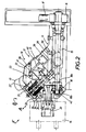
- la figure 2 représente une vue en coupe axiale de la tête revolver représentée par la figure 1,
- la figure 3 représente la tête revolver selon l'invention, partiellement coupée et vue selon une direction indiquée par la flèche F,
- la figure 4 représente une vue en perspective d'une forme de réalisation où la tourelle porte six broches porte-outil, et
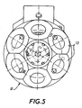
- la figure 5 illustre une vue de dessous de la tête rèvolver illustrée par la figure 4.
- FIG. 1 represents a perspective view of a preferred embodiment of the revolver head of the invention,
- FIG. 2 represents a view in axial section of the revolver head represented by FIG. 1,
- FIG. 3 represents the revolver head according to the invention, partially cut and seen in a direction indicated by the arrow F,
- FIG. 4 represents a perspective view of an embodiment where the turret carries six tool-holder pins, and
- FIG. 5 illustrates a bottom view of the revolver head illustrated in FIG. 4.
En référence à la figure 1, la tête revolver pour machine-outil 10 représentée comporte essentiellement un bâti fixe 11 sur lequel est adaptée une tourelle 12 porte-broches qui, comme son nom l'indique, porte par exemple trois broches porte-outil 13 disposées à 120° l'une de l'autre. Les broches 13 pourraient être remplacées par des adaptations 14 du type multibroche connues en soi. Il est bien entendu que le nombre de broches ou d'adaptations multibroches n'est pas limité à trois, bien que cette construction soit avantageuse dans certains cas pour des raisons d'encombrement.Referring to Figure 1, the revolver head for
La figure 2 représente une vue en coupe détaillée de la tête revolver 10. Le bâti fixe 11, de forme coudée à 90°, contient essentiellement l'arbre d'entraînement 15 portant à son extrémité éloignée de la tourelle une roue ou un pignon d'entraînement 16 sur lequel passe une courroie 17 et à son autre extrémité un pignon d'entraînement 18 qui peut engrener un pignon d'entraînement 19 solidaire de la tête porte-outil 20 de la broche 13.2 shows a detailed sectional view of the
La tourelle 12 est disposée par rapport au bâti, de telle manière que son axe fasse avec l'aie de l'arbre d'entraînement 15, un angle de 45°.The
Cette disposition particulièrement avantageuse permet un dégagement optimal des broches ou multibroches par rapport à celle qui se trouve en position d'usinage et qui est parallèle à l'arbre d'entraînement.This particularly advantageous arrangement allows optimal disengagement of the spindles or multi-spindles relative to that which is in the machining position and which is parallel to the drive shaft.
En outre, les efforts d'usinage sont absorbés de façon idéale, ce qui n'est pas le cas des autres broches connues qui subissent un couple de renversement lorsqu'elles sont en position d'usinage.In addition, the machining forces are ideally absorbed, which is not the case with the other known spindles which undergo an overturning torque when they are in the machining position.
La tourelle 12 peut se déplacer par rapport au bâti fixe 11 selon un mouvement axial illustré par la flèche double A et selon un mouvement rotatif illustré par la double flèche B. A cet effet, la tourelle se compose de deux éléments respectivement 21 et 22, dont le premier 21 est solidaire du bâti fixe et dont le deuxième 22, en forme de couvercle, s'emboîte en partie sur ledit premier élément. Le premier élément 21, qui est rigidement fixé au bâti fixe 11, porte un manchon ou fourrure 23 à l'intérieur duquel peut tourner autour de son axe une tige cylindrique 24 à l'extrémité supérieure de laquelle est fixé un piston axial 25, dont le rôle sera expliqué par la suite. Le piston 25 est logé dans une chambre ménagée à l'intérieur d'un capuchon 26 de forme sensiblement cylindrique, qui est fixé au second élément 22 de la tourelle au moyen de vis ou boulons 27. Un ressort de compression 28, composé de préférence d'un empilement de rondelles de Belleville, est logé partiellement dans une première cavité annulaire ménagée à la base du piston 25, coaxiale par rapport à la tige 24, et partiellement dans une seconde cavité annulaire prolongeant la précédente et ménagée dans le second élément 22 de la tourelle coaxialement par rapport à cette même tige 24.The
Le bâti fixe 11 est équipé d'un conduit 29 comprenant une embouchure 30 et une tubulure linéaire 31 qui débouche dans un conduit axial 32 ménagé à travers la tige 24 et le piston 25 pour déboucher dans une chambre de pression 33 ménagée entre le piston 25 et la paroi intérieure du capuchon 26.The
Lorsque l'on injecte un fluide sous pression dans l'embouchure 30, la pression du fluide hydraulique qui est transmise par les conduits 31 et 32 se manifeste dans la chambre 33, ce qui a pour effet de déplacer le capuchon 26 par rapport au piston 25. Etant donné que le capuchon 26 est rendu solidaire du second élément 22 de la tourelle par les boulons 27, ce deuxième élément se soulève par rapport au premier élément 21 en comprimant le ressort 28, du fait de l'écrasement des rondelles de Belleville dont il est constitué. Le second élément 22 de la tourelle est par ailleurs équipé d'au moins une goupille ou d'un boulon 34 dont la tête pénètre dans une cavité 35 ménagée a la base du piston axial 25 et dont le but est de rendre momentanément solidaires ledit second élément de la tourelle et ledit piston. Dans cette position, le piston peut servir d'élément moteur destiné à entraîner la tourelle en rotation selon un mouvement qui sera décrit plus en détail ci-dessous.When a fluid under pressure is injected into the
La tige 24, qui est solidaire du piston 25, porte à son extrémité inférieure un piston rotatif 36 logé dans une chambre cylindrique 37 ménagée dans le premier élément 21 de la tourelle. Ce piston rotatif peut, comme le montre plus particulièrement la figure 3, être amené en butée dans deux positions différentes respectivement 36a et 36b, selon que l'on injecte du fluide hydraulique d'un côté ou de l'autre de ce piston rotatif dans la chambre 37. Etant donné que le piston rotatif 36 est solidaire du piston 25, par l'intermédiaire de la tige 24 et que ce dernier est momentanément rendu solidaire, par au moins une goupille 34, du second élément 22 de la tourelle, cette dernière peut tourner d'un angle de 120° pour permuter les broches. Lorsque l'on relâche la pression dans la chambre de pression 33, le capuchon 26 revient dans sa position initiale, poussé par le ressort 28, ce qui dégage la tête de la ou des goupilles 34 de l'évidement correspondant 35 et désolidarise le piston 25 du second élément 22 de la tourelle. Par une injection appropriée de fluide sous pression, on ramène le piston rotatif 36 dans sa position initiale, ce qui le rend prêt pour un nouveau cycle de travail permettant de faire tourner la tourelle, ou plus exactement la seconde partie 22 de la tourelle, d'un angle de 120° (dans le cas où la tourelle porte trois broches porte-outil) par rapport à la première partie 21 de cette tourelle ou du bâti fixe.The rod 24, which is integral with the
Le pignon d'entraînement 18 des moyens d'entraînement des broches comprend une première partie 18a cylindrique et une seconde partie 18b tronconique formée à l'extrémité antérieure de cet organe. En fonctionnement normal, la partie cylindrique engrène le pignon d'entraînement 19. Lorsque l'on soulève la tourelle, c'est-à-dire lorsque l'on déplace, comme décrit précédemment la seconde partie 22 axialement par rapport à la première partie 21 de cette tourelle, le pignon 19 reste en prise avec le pignon 18 grâce à l'existence de la partie tronconique 18b dont l'angle est de 45°. Cette forme de réalisation permet d'assurer un indexage précis des roues d'entraînement. A cet effet, la partie tronconique 18b est en appui contre la partie cylindrique 18a grâce à un ressort de compression 42 constitué par des rondelles de Belleville empilées. Le ressort a pour objet d'absorber les contraintes momentanées pouvant s'exercer sur les dents si, lors d'un changement de broche, les dents du pignon 19 tombent en face des dents du pignon 18, et d'éviter ainsi un blocage de l'entraînement, voire un endommagement des pignons.The
En référence à la figure 3, des goupilles d'indexage 38, disposées entre deux surfaces correspondantes du premier et du second élément de la tourelle, permettent d'indexer d'une manière précise ce second élément 22 par rapport au premier élément de cette tourelle.. Dans le cas d'une tourelle portant trois broches, les goupilles sont au nombre de six et sont décalées de 60°. Ces goupilles pourraient également être remplacées par des éléments en relief de l'un des éléments s'engageant dans des cavités complémentaires de l'autre élément.With reference to FIG. 3, indexing
Un multicontacteur 39 permet d'assurer les commandes électriques du dispositif. Ce multicontacteur est logé dans une cavité ménagée dans le bâti. Il est associé à au moins deux tiges 40 de commande correspondant respectivement auxdites broches porte-outil, dont chacune porte par exemple une goupille de commande 41 qui est destinée à agir sur une des tiges de commande 40 pour actionner l'un des contacts du multicontacteur.A
Les figures 4 et 5 illustrent une variante selon laquelle la tourelle 12 de la tête rèvolver 10 porte six broches porte-outils 13 qui sont montées à 60° l'une de l'autre. Comme précédemment, ces broches pourraient être remplacées par des éléments d'adaptation multibroches. La construction de cette réalisation est basée sur les mêmes principes que ceux qui sont mis en oeuvre pour la réalisation de la tête rèvolver selon les figures précédentes. L'angle de rotation de la tête pour passer d'une broche à une autre est de 60°. La présence de six broches augmente la souplesse de la machine et accroît ses capacités. Le mécanisme d'entraînement des broches reste similaire à celui décrit précédemment.Figures 4 and 5 illustrate a variant in which the
Parmi les éléments originaux et les avantages de la présente invention, on peut noter :
- le principe particulièrement efficace d'un système de synchronisation réalisé de manière très simple par la combinaison des deux parties du pignon d'entraînement 18 couplées grâce à un ressort de compression,
- la présence, dans le bâti, du multicontacteur logé dans un boîtier étanche et dont les contacts sont commandés par des tiges et des goupilles de commande,
- la simplicité d'un éventuel remplacement du multicontacteur 39 qui ne nécessite aucun réglage sur la machine, ce dernier pouvant être effectué en usine,
- l'indexation de la tourelle sur des goupilles, ce qui autorise de tès fortes sollicitations radiales en cours d'utilisation des broches,
- la position indexée de la tourelle assurée mécaniquement par des rondelles de Belleville, ce qui évite tout risque en cas de chute accidentelle de la pression hydraulique,
- l'extrême simplicité du circuit hydraulique qui comporte un piston axial et un piston rotatif et ne nécessite qu'une petite centrale hydraulique de très faible capacité. Ce circuit assure, en 1,5 secondes, le soulèvement de la tourelle pour désindexer les goupilles 38, craboter le
piston 25 dans la goupille 34 et désengager le pignon 19, qui assure la rotation de 60° ou de 120° de la tourelle. La chute de la pression hydraulique permet, par les rondelles de Belleville de réindexer les goupilles 38, de désindexer lepiston 25, ce qui permet aupiston rotatif 36 de reprendre sa position initiale, - toutes les pièces mécaniques en mouvement sont plongées dans un bain d'huile ce qui permet à cette tête de s'implanter soit verticalement soit horizontalement.
- the particularly effective principle of a synchronization system produced very simply by the combination of the two parts of the
drive pinion 18 coupled by means of a compression spring, - the presence, in the frame, of the multicontactor housed in a sealed housing and the contacts of which are controlled by rods and control pins,
- the simplicity of a possible replacement of the
multicontactor 39 which does not require any adjustment on the machine, the latter being able to be carried out in the factory, - the indexing of the turret on pins, which allows very strong radial stresses during use of the spindles,
- the indexed position of the turret provided mechanically by Belleville washers, which avoids any risk in the event of an accidental drop in hydraulic pressure,
- the extreme simplicity of the hydraulic circuit which comprises an axial piston and a rotary piston and requires only a small hydraulic power station of very low capacity. This circuit ensures, in 1.5 seconds, the lifting of the turret to deindex the
pins 38, clutch thepiston 25 in the pin 34 and disengage thepinion 19, which ensures the rotation of 60 ° or 120 ° of the turret. The drop in hydraulic pressure makes it possible, through Belleville washers, to reindex thepins 38, to deindex thepiston 25, which allows therotary piston 36 to return to its initial position, - all the moving mechanical parts are immersed in an oil bath which allows this head to settle either vertically or horizontally.
Claims (10)
- Revolving head for machine tool, including a stationary frame, a mobile toolhead turret which rotates with respect to this frame, at least two toolhead spindles mounted on said turret, a system for driving the rotation of said spindles including a drive shaft (15) and an automatic control system for traverse motion of said turret, in which the turret (12) includes a first part (21) of a piece with said frame (11) and a second part (22) which is mobile with respect to the first part, in which the said automatic control system includes an axial piston (25) and a rotating piston (36) for driving the said second part (22) of the turret (12) axially and in rotation respectively with respect to the said first part (21), in which the axis of the drive shaft (15) forms an angle of 45° with the axis of the turret (12), characterized in that the axial piston includes a rod (24) which is of a piece with the first part (21) of the turret and of said stationary frame (11), and a body including a cap (26) of a piece with the second part (22) of the turret, and mobile axially and in rotation with respect to the said rod, and in that it includes a compression spring component (28) mounted between the base of the piston (25) and the said second part (22) of the turret, this spring component being designed to bring the said second part (22) up against the said first part (21) of the turret after an axial movement relative to these two parts.
- Revolving head according to claim 1, characterized in that said compression spring component (28) is mounted partly in a first ring-shaped cavity hollowed out of the base of the piston (25) and partly in a second ring-shaped cavity hollowed out of the said second part (22) of the turret (12), these two ring-shaped cavities being placed coaxially with respect to the said rod (24) as extensions of each other.
- Revolving head according to claim 4, characterized in that the compression spring component (28) is made up of a pile of Belleville spring washers.
- Revolving head according to claim 1, characterized in that the rotating piston (36) is mounted at the end of the rod (24) and is lodged inside a cylindrically shaped chamber (37).
- Revolving head according to claim 1, characterized in that the axial piston (25) includes at least one recess (35) and in that the said second part (22) of the turret carries at least one pin (34) fitted so as to lodge in the said recess or recesses (35), these two components being designed to make the said axial piston (25), which is of a piece with the rod (24), of the said second part (22) of the turret when the turret is axially displaced with respect to the first part (21).
- Revolving head according to claim 1, characterized in that the system driving the spindles including a cogged drive pinion (18) of a piece with a drive shaft (15), this cogged pinion including a cylindrical part (18a) and a truncated part (18b), and a cogged drive pinion (19) of a piece with a drive shaft of a spindle (20) which is always in mesh at least with the truncated part of the drive pinion of the drive shaft.
- Revolving head according to claim 6, characterized in that the generating lines of the said truncated part (18b) form an angle of 45° with the axis of the pinion, and are parallel to the axis of the rod (24).
- Revolving head according to claim 6, characterized in that the truncated part (18b) and the cylindrical part (18a) of the drive pinion are kept in contact with each other by a spring component (42) and thus coupled.
- Revolving head according to claim 8, characterized in that the spring component (42) is made up of a pile of Belleville spring washers.
- Revolving head according to claim 1, characterized in that it includes a multicontact switch (39) lodged in a cavity hollowed out of the frame, this multicontact switch being designed to control the electrical operations of this head, and at least two control rods (40) corresponding respectively to the said toolhead spindles, and associated with control pins (41) corresponding respectively to each of the spindles and designed to activate the said multicontact switch (39) through one of the said control rods.
Priority Applications (1)
| Application Number | Priority Date | Filing Date | Title |
|---|---|---|---|
| AT89906373T ATE92821T1 (en) | 1988-05-25 | 1989-05-24 | TURRET FOR MACHINE TOOLS. |
Applications Claiming Priority (2)
| Application Number | Priority Date | Filing Date | Title |
|---|---|---|---|
| FR8807142 | 1988-05-25 | ||
| FR8807142A FR2631872A1 (en) | 1988-05-25 | 1988-05-25 | REVOLVER HEAD FOR MACHINE TOOL |
Publications (2)
| Publication Number | Publication Date |
|---|---|
| EP0416003A1 EP0416003A1 (en) | 1991-03-13 |
| EP0416003B1 true EP0416003B1 (en) | 1993-08-11 |
Family
ID=9366716
Family Applications (1)
| Application Number | Title | Priority Date | Filing Date |
|---|---|---|---|
| EP89906373A Expired - Lifetime EP0416003B1 (en) | 1988-05-25 | 1989-05-24 | Revolving head for machine tool |
Country Status (7)
| Country | Link |
|---|---|
| US (1) | US5146663A (en) |
| EP (1) | EP0416003B1 (en) |
| JP (1) | JPH03504471A (en) |
| DE (1) | DE68908410T2 (en) |
| ES (1) | ES1010415Y (en) |
| FR (1) | FR2631872A1 (en) |
| WO (1) | WO1989011376A1 (en) |
Families Citing this family (8)
| Publication number | Priority date | Publication date | Assignee | Title |
|---|---|---|---|---|
| GB2273067B (en) * | 1992-11-24 | 1996-04-10 | Honda Motor Co Ltd | Turret machine tool |
| IT1268332B1 (en) * | 1994-09-16 | 1997-02-27 | Sasib Spa | HANDLING DEVICE FOR HANDLING, IN PARTICULAR FOR THE ORIENTATION OF PIECES, TOOLS OR SIMILAR. |
| IT1283209B1 (en) * | 1996-03-08 | 1998-04-16 | Riello Macchine Utensili Spa | TOOL CHANGE DEVICE FOR MACHINE TOOL OPERATING UNITS |
| DE19618757C2 (en) * | 1996-05-09 | 2001-02-22 | Witzig & Frank Turmatic Gmbh | Machine tool |
| US6785943B2 (en) | 1998-09-04 | 2004-09-07 | Hardinge, Inc. | Indexing tool turret |
| US6442815B1 (en) | 2000-04-18 | 2002-09-03 | The Regents Of The University Of Michigan | Reconfigurable automatic tool changer |
| FR2856945B1 (en) * | 2003-07-02 | 2005-11-25 | Ind Automation | ASSEMBLY MACHINE |
| US7509720B2 (en) * | 2007-11-05 | 2009-03-31 | Wawrzyniak Walter W | Continuous tool rotation tool turret |
Family Cites Families (10)
| Publication number | Priority date | Publication date | Assignee | Title |
|---|---|---|---|---|
| US2915922A (en) * | 1955-09-07 | 1959-12-08 | Warner Swasey Co | Indexible tool holder |
| NL236924A (en) * | 1958-03-10 | |||
| GB1025019A (en) * | 1964-05-18 | 1966-04-06 | Cincinnati Milling Machine Co | Lathe |
| FR2055944A5 (en) * | 1969-08-08 | 1971-05-14 | Berthiez C N M P | |
| GB1310931A (en) * | 1970-02-03 | 1973-03-21 | Autologic Ltd | Machine tools |
| FR2243757B1 (en) * | 1973-09-15 | 1978-11-24 | Sauter Kg Feinmechanik | |
| FR2362703A1 (en) * | 1976-08-30 | 1978-03-24 | Komatsu Mfg Co Ltd | COMPLEX MACHINE-TOOL INTENDED FOR MULTIPLE MACHINING |
| DE3216892A1 (en) * | 1982-05-06 | 1983-11-10 | Index-Werke Kg Hahn & Tessky, 7300 Esslingen | MULTI-SPINDLE REVOLVER TURNING MACHINE |
| JPS6347003A (en) * | 1986-08-12 | 1988-02-27 | Howa Mach Ltd | Tallet unit |
| CA1304924C (en) * | 1986-10-09 | 1992-07-14 | Masao Hiraguri | Turret apparatus |
-
1988
- 1988-05-25 FR FR8807142A patent/FR2631872A1/en active Pending
-
1989
- 1989-05-24 ES ES8901676U patent/ES1010415Y/en not_active Expired - Fee Related
- 1989-05-24 JP JP1506153A patent/JPH03504471A/en active Pending
- 1989-05-24 DE DE89906373T patent/DE68908410T2/en not_active Expired - Fee Related
- 1989-05-24 WO PCT/FR1989/000247 patent/WO1989011376A1/en active IP Right Grant
- 1989-05-24 US US07/613,623 patent/US5146663A/en not_active Expired - Fee Related
- 1989-05-24 EP EP89906373A patent/EP0416003B1/en not_active Expired - Lifetime
Also Published As
| Publication number | Publication date |
|---|---|
| DE68908410D1 (en) | 1993-09-16 |
| EP0416003A1 (en) | 1991-03-13 |
| US5146663A (en) | 1992-09-15 |
| DE68908410T2 (en) | 1994-02-17 |
| FR2631872A1 (en) | 1989-12-01 |
| JPH03504471A (en) | 1991-10-03 |
| ES1010415Y (en) | 1990-06-16 |
| WO1989011376A1 (en) | 1989-11-30 |
| ES1010415U (en) | 1990-01-01 |
Similar Documents
| Publication | Publication Date | Title |
|---|---|---|
| EP0416003B1 (en) | Revolving head for machine tool | |
| FR2696666A1 (en) | Micrometric device for finishing high precision bores. | |
| EP0954412A1 (en) | Pilot tool for centring and clamping | |
| EP0214090B1 (en) | Drive mechanism for tool holders in a machine tool | |
| FR2700486A1 (en) | Indexed actuation head for automatic machine tools. | |
| EP3209458B1 (en) | Improved vibratory machining device | |
| EP0418145A1 (en) | Pressure element for clamping workpieces | |
| EP1238737B1 (en) | Tapping unit | |
| EP0245177A1 (en) | Supporting device of a work piece for working the fifth face | |
| FR2687338A1 (en) | Improved milling head | |
| EP3307462B1 (en) | Lathe and guide bushing | |
| EP0192586A1 (en) | Automatic screw thread cutting device | |
| FR2657281A1 (en) | MACHINE FOR PRUNING GEARS. | |
| WO2005044510A2 (en) | Suction device associated with the tool of a cutting machine tool | |
| FR2704789A1 (en) | Revolving multi-spindle head for machine tool | |
| EP0128811B1 (en) | Tool changing apparatus for machine tools | |
| EP0154584B1 (en) | Device for automatic recovery of play for clutch | |
| FR2467052A1 (en) | Robot tool-change for lathe - uses step rotating tool and magazine wheels on parallel axes with latter reciprocating axially to effect change | |
| EP0074452A1 (en) | Milling head coupling device | |
| EP0443019A1 (en) | Tool-changing device for machine-tools | |
| EP0098409A1 (en) | Device for operating a pivoting charging chute | |
| EP4084922B1 (en) | Electrospindle with integrated feed with automatic tool holder change | |
| FR2543866A1 (en) | Device for automatically blocking and unblocking a tool in a machine tool rotary spindle | |
| FR2800650A1 (en) | MACHINE FOR FORMING TUBE ENDS | |
| FR2688435A1 (en) | Device for tapping on a press |
Legal Events
| Date | Code | Title | Description |
|---|---|---|---|
| PUAI | Public reference made under article 153(3) epc to a published international application that has entered the european phase |
Free format text: ORIGINAL CODE: 0009012 |
|
| 17P | Request for examination filed |
Effective date: 19901113 |
|
| AK | Designated contracting states |
Kind code of ref document: A1 Designated state(s): AT BE CH DE FR GB IT LI LU NL SE |
|
| 17Q | First examination report despatched |
Effective date: 19920406 |
|
| RAP1 | Party data changed (applicant data changed or rights of an application transferred) |
Owner name: SOMEX MULHOUSE S.A. |
|
| GRAA | (expected) grant |
Free format text: ORIGINAL CODE: 0009210 |
|
| AK | Designated contracting states |
Kind code of ref document: B1 Designated state(s): AT BE CH DE FR GB IT LI LU NL SE |
|
| PG25 | Lapsed in a contracting state [announced via postgrant information from national office to epo] |
Ref country code: SE Effective date: 19930811 Ref country code: NL Effective date: 19930811 Ref country code: GB Effective date: 19930811 Ref country code: AT Effective date: 19930811 |
|
| REF | Corresponds to: |
Ref document number: 92821 Country of ref document: AT Date of ref document: 19930815 Kind code of ref document: T |
|
| REF | Corresponds to: |
Ref document number: 68908410 Country of ref document: DE Date of ref document: 19930916 |
|
| ITF | It: translation for a ep patent filed |
Owner name: DOTT. FRANCO CICOGNA |
|
| NLV1 | Nl: lapsed or annulled due to failure to fulfill the requirements of art. 29p and 29m of the patents act | ||
| GBV | Gb: ep patent (uk) treated as always having been void in accordance with gb section 77(7)/1977 [no translation filed] |
Effective date: 19930811 |
|
| PG25 | Lapsed in a contracting state [announced via postgrant information from national office to epo] |
Ref country code: LU Free format text: LAPSE BECAUSE OF NON-PAYMENT OF DUE FEES Effective date: 19940531 Ref country code: BE Effective date: 19940531 |
|
| PLBE | No opposition filed within time limit |
Free format text: ORIGINAL CODE: 0009261 |
|
| STAA | Information on the status of an ep patent application or granted ep patent |
Free format text: STATUS: NO OPPOSITION FILED WITHIN TIME LIMIT |
|
| 26N | No opposition filed | ||
| BERE | Be: lapsed |
Owner name: S.A. SOMEX MULHOUSE Effective date: 19940531 |
|
| PGFP | Annual fee paid to national office [announced via postgrant information from national office to epo] |
Ref country code: DE Payment date: 19950527 Year of fee payment: 7 |
|
| PGFP | Annual fee paid to national office [announced via postgrant information from national office to epo] |
Ref country code: FR Payment date: 19950531 Year of fee payment: 7 |
|
| PGFP | Annual fee paid to national office [announced via postgrant information from national office to epo] |
Ref country code: CH Payment date: 19950712 Year of fee payment: 7 |
|
| PG25 | Lapsed in a contracting state [announced via postgrant information from national office to epo] |
Ref country code: LI Effective date: 19960531 Ref country code: CH Effective date: 19960531 |
|
| REG | Reference to a national code |
Ref country code: CH Ref legal event code: PL |
|
| PG25 | Lapsed in a contracting state [announced via postgrant information from national office to epo] |
Ref country code: FR Effective date: 19970131 |
|
| PG25 | Lapsed in a contracting state [announced via postgrant information from national office to epo] |
Ref country code: DE Effective date: 19970201 |
|
| REG | Reference to a national code |
Ref country code: FR Ref legal event code: ST |
|
| PG25 | Lapsed in a contracting state [announced via postgrant information from national office to epo] |
Ref country code: IT Free format text: LAPSE BECAUSE OF NON-PAYMENT OF DUE FEES;WARNING: LAPSES OF ITALIAN PATENTS WITH EFFECTIVE DATE BEFORE 2007 MAY HAVE OCCURRED AT ANY TIME BEFORE 2007. THE CORRECT EFFECTIVE DATE MAY BE DIFFERENT FROM THE ONE RECORDED. Effective date: 20050524 |