EP0193012A2 - Machine à imprimer - Google Patents
Machine à imprimer Download PDFInfo
- Publication number
- EP0193012A2 EP0193012A2 EP86101617A EP86101617A EP0193012A2 EP 0193012 A2 EP0193012 A2 EP 0193012A2 EP 86101617 A EP86101617 A EP 86101617A EP 86101617 A EP86101617 A EP 86101617A EP 0193012 A2 EP0193012 A2 EP 0193012A2
- Authority
- EP
- European Patent Office
- Prior art keywords
- printing
- cylinders
- bearers
- cylinder
- thrown
- Prior art date
- Legal status (The legal status is an assumption and is not a legal conclusion. Google has not performed a legal analysis and makes no representation as to the accuracy of the status listed.)
- Granted
Links
Images


Classifications
-
- B—PERFORMING OPERATIONS; TRANSPORTING
- B41—PRINTING; LINING MACHINES; TYPEWRITERS; STAMPS
- B41F—PRINTING MACHINES OR PRESSES
- B41F13/00—Common details of rotary presses or machines
- B41F13/08—Cylinders
- B41F13/24—Cylinder-tripping devices; Cylinder-impression adjustments
- B41F13/26—Arrangement of cylinder bearings
- B41F13/32—Bearings mounted on swinging supports
Definitions
- the present invention pertains generally to printing units of a printing press and more particularly to an improved system for mounting the cylinders of such printing units.
- Conventional web offset perfecting printing units include two printing couples, each couple comprising a plate cylinder and a blanket cylinder.
- the plate cylinder of each couple is disposed in rolling engagement with the blanket cylinder whereby it transfers an ink impression onto a blanket cylinder.
- the blanket cylinder transfers the ink to the web material with which it is in rolling contact in the form of a printed image.
- the second printing couple likewise includes a second plate cylinder and a second blanket cylinder which prints on a second side of the web of material simultaneously with the printing on the first side by the first blanket cylinder.
- cylinder bearer supports as taught, for example, in United States Patent No. 3,256,812.
- Such bearer supports or rings are fitted to the shafts of the cylinders and are of such'diameter relative to that of the associated cylinders that the bearer rings of one cylinder rotate in engagement with the bearer rings of an adjacent cylinder when the cylinders are in the "thrown on" or printing position.
- the berarer rings serve, among other things, to regulate the spacing between the cylinders without creation of excessive pressure between the cylinder surfaces themselves.
- the bearer rings By interconnecting the adjacent cylinders, the bearer rings have significantly improved the stability of color register, assisted in defining proper blanket squeeze and, particularly in single-width presses with hollow cylinders, markedly reduced cylinder bouncing which is the major cause of streaking.
- a printing press includes an improved method and apparatus for moving printing cylinders between thrown off positions in which bearers connected with the cylinders are separated and thrown on or printing positions.
- the printing cylinders are urged to their thrown off positions by springs which, in one embodiment of the invention, apply a biasing force to pivotally mounted support arms for the cylinders.
- the cylinders are mounted on cantilevered leaf springs which urge the cylinders toward their thrown off positions.
- a motor is provided to apply a force directly to one of the printing cylinders to move it from its thrown off position to its printing position.
- the other printing cylinders are moved from their thrown off positions to their printing positions under the influence of forces transmitted between bearers connected with the printing cylinders.
- a first one of the printing cylinders is moved from its thrown off position to a position in which the bearers connected with the first printing cylinder are in abutting engagement with the bearers connected with a second printing cylinder.
- Continued operation of the motor moves the first and second printing cylinders together away from their thrown off positions to a position in which the bearers connected with the second printing cylinder are in abutting engagement with the bearers connected with a third printing cylinder.
- Still further operation of the motor moves the first, second and third printing cylinders together away from their thrown off positions until the cylinders are in their printing positions.
- Another object of this invention is to provide a new and improved method of moving printing cylinders between thrown off and printing positions and in which the printing cylinders are moved from their thrown off positions to positions in which bearers connected with the printing cylinders. are in abutting engagement and, wherein, the printing cylinders are then moved together, away from their thrown off positions with their bearers in engagement until they are in their printing positions.
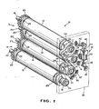
- FIG. 1 there is shown a portion of an offset, lithographic perfecting printing press 10 constructed in accordance with the invention.
- Such presses'conventionally comprise an upper printing unit 11 including a top plate cylinder 12 and a cooperating top blanket cylinder 13, and a lower printing unit 14 including a bottom plate cylinder 15 and a bottom blanket cylinder 16.
- a web of material to be printed (not shown) is fed between the counterrotating blanket cylinders 12 and 14 in a left-to-right direction as viewed in Figs. 1 to 3 so as to be printed on both surfaces in conventional fashion.
- suitable inkers and dampeners are employed in conjunction with the top and bottom plate and blanket cylinders to complete the upper and lower printing units.
- the cylinder 12 includes stub shafts 17 and 18 at its opposite ends by means of which it is mounted for rotation about its longitudinal axis.
- the blanket cylinder 13 includes stub shafts 19 and 20, the bottom plate cylinder 15 has stub shafts 21 and 22, and the bottom blanket cylinder 16 has stub shafts 23 and 24, by which they are mounted for rotation about their respective longitudinal axes.
- Affixed to the stub shafts 18, 20, 22 and 24 are-:gears 25, 26, 27 and-28, respectively, for driving the associated cylinders as by means of a drive unit (not shown) in driving engagement with one of the aforementioned gears.
- the teeth of the gears 25 through 28 are of such depth that the gears remain intermeshed so as to be capable of driving the cylinders when in the throw off mode, as well as while the cylinders are in the throw on operating configuration.
- Bearer rings 29 are located at the ends of each of the cylinders 12 through 15, with the bearer rings at each end being, aligned and of a diameter relative to their associated cylinder such that the bearer rings-of one cylinder rotate in engagement with the bearer rings of the next adjacent cylinder or cylinders when the cylinders are in the throw on, printing position.
- the cylinders 12, 13 and 16 are supported, at their ends by a frame of the press, a fragment of the frame being shown generally at 30. More particularly, the stub shafts 23 and 24 of the bottom plate cylinder 15 are mounted in journals 31 carried by the frame 30. Therefore the central axis of the cylinder is in a generally fixed position. It will be appreciated that while for purposes of simplification and clarity, the mounting arrangement has been illustrated and will be discussed for only one end of the cylinders, a generally identical arrangement is also provided at the opposite end.
- opposite axial ends'of the top plate cylinder 12 and the top and bottom blanket cylinders 13 and 16 are carried by pivotal support members or arms, as best shown in Figs. 1 to 3 for one of the axial ends of the cylinders. It should be understood that although only the mounting arrangement for the right (as viewed in Fig. 1) ends of the cylinders have been shown in Fig. 1, the left ends of the cylinders are supported in the same manner as the right ends.
- the stub shafts 21 and 22 of the bottom blanket cylinder 16 are mounted in journals 32 carried by pivot or swing arms 33 pivotally supported upon ; the frame 30 by pins 34.
- the stub shafts 19 and 20 of the top blanket cylinder 13 are mounted in journals 35 carried by pivot or swing arms 36 pivotally supported upon the frame 30 bv pins 37.
- the stub shafts 17 and 18 of the top plate cylinder 12 are received in journals 38 carried by pivot or swing arms 39 pivotally supported at the frame 30 by pivot pins 40.
- the arms 33, 36 and 39 are thus free to swing about the pivot pins within the limits whereby the cylinders 16, 13 and 12, respectively, can move between the throw on and throw off positions as will be hereinafter explained.
- Compression of the cylinder stack is provided by means of a pair of pressure cylinder units, one of which is shown at 41, at each end of the cylinder stack.
- the cantilever arms 39 include extensions 42 whose outer ends are pivotally connected at 43 to the piston rods 44 of cylinders 45.
- the cylinders are connected at their opposite ends by pins 46 to brackets 47 affixed to the frame 30.
- the cylinders 45 may be of a conventional air or hydraulic type wherein by application of appropriate pressure to the working fluid, the piston will be urged inwardly or retracted to, in turn, maintain a desired downward force upon the cantilever arm 39 as will be hereinafter described.
- a similar cylinder unit is disposed at the opposite end of the plate cylinder.
- Throw off or separation of the cylinders 12, 13 and 16 is accomplished by means of spring assemblies or retractors, illustrated generally at 48 in Fig. 2, acting against the cantilever arms 39, 36 and 33, respectively, to urge the arms to pivot upwardly about their respective pivot pins 34, 37 and 40 when the compression force of the pressure cylinder units 41 is reduced or removed.
- Adjustable stops 49 are provided opposite the retractors 48 for defining the upper limit of movement of the cantilever arms 50 so that the throw on and throw off positions of the cylinders will be within prescribed limits. It should be understood that retractors and stops, corresponding to the retractors and stops 48 and 49, are associated with the opposite ends of the printing cylinders 12, 13 and 16.
- the retractors 48 comprise an-open ended tubular bracket 50 affixed to the frame 30 as by bolts 51 (Fig. 5).
- a compression spring 52 within the tubular bracket bears against a flange 53 on the cantilever arms 33 or 36 or a planar segment 54 on the extension 42 of the cantilever arm 39 to urge the arms upwardly.
- Adjustment of the force of the compression spring against the arm is provided by means of a threaded insert 55 (Fig. 2) in the bottom of the tubular bracket having a platform 56 bearing against the bottom of the spring. By turning the insert as with an Allen wrench the platform can be moved up or down within the tubular bracket to vary the effective force of the spring.
- the adjustable stops 49 include a tube 57 affixed to the frame 30 as by a stud 58.
- a bolt 59 extends through the tube with its head 60 adapted for engagement of the tops of the flanges 53 or extension 42 of the cantilever arm 39 as the case may be.
- Belleville springs 61 are provided on the bolt 59 between the head and the bottom of the tube 57, and jam nuts 62 are threaded on the bolt by means of which a predetermined compressive force can be established and maintained in the springs.
- the springs may be precompressed to a force of five hundred pounds, that is, the top would resist a force of up to five hundred pounds applied to the head 60 by the flange 53, and would then yield if a greater force were applied.
- this feature may be important in preventing creation of excessive forces upon the cylinders in the event of a web wrapup.
- Fig. 3 a feature of the invention whereby the inker rolls for the top plate cylinder 12 are in floating engagement with the cylinder.
- the bottom plate cylinder 15 does not, of course, move during throw off so that the inner rolls therefore can be mounted in the customary stationary manner.
- top ink form rolls 63 are journalled at their ends in side plates 64 pivotally supported at 65 upon a segment of the press frame 30.
- One or more ink vibrators 66 may also be journalled in the side plates for engagement with the ink form rolls in the customary fashion.
- Ink form rolls 67 and an ink vibrator 68 are journalled in side plates 69 which may be affixed to the press frame 30 so that the form rolls 67 will be in rolling engagement with the stationary bottom plate cylinder 15.
- the top ink form rolls 63 inasmuch as they are carried by the pivotally mounted side plates 64, operate in floating engagement with the top plate cylinder 12.
- the plate cylinder 12 and blanket cylinders 13 and 16 are illustrated in Fig. 3 in their throw off position wherein the precompressing force of the pressure cylinder units 41 has been released and the cantilever arms carrying the cylinders have been urged upwardly by the retractors 48 into engagement with their respective stops 49.
- the ink form rolls 63 likewise move and remain in operative engagement with the plate cylinder.
- the cylinder mounting mechanism of the present invention is particularly well adapted to the mounting of the plate and blanket cylinders with their axes in linear alignment or near linear alignment as opposed to the offsetting of the cylinders. which is necessary to accommodate throw off movement of cylinders mounted in conventional eccentrics.
- the cylinders 12, 13, 15 and 16 of the embodiment of Figs. 1 to 3 have been illustrated.with their longitudinal axes offset, they could be mounted in vertically aligned relationship where desired for purposes of conserving space and providing improved accessibility as in presses employing a plurality of such printing units in series.
- the lower plate cylinder 15 is mounted for rotation about a fixed axis. However, if desired, the lower plate cylinder could be pivotally mounted in the same manner as the cylinders 12, 13 and 16. If this was done, the lower inker rollers 67 and 68 would be pivotally mounted in the same manner as the upper inker rollers.
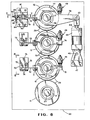
- FIGs. 6 through 8 there is illustrated in Figs. 6 through 8 an embodiment of the invention employing an alternate form of cantilever support for the plate and blanket cylinders 12, 13, 15 and 16, the cylinders being arranged in a vertically aligned configuration.
- the embodiment is identical to that of Figs. 1 to 5 and accordingly, where appropriate, like numerals are employed to designate like parts.
- the journals 31 for the bottom plate cylinder 15 are again carried by the press frame 30 with the cylinder being in a generally fixed position.
- the web cylinders 13 and 16 and top plate cylinder 12 are carried in cantilever fashion for throw off.
- To that end the journals 32 of the bottom blanket cylinder 16 are mounted in journal boxes 70 affixed as by fasteners 71 to the end of a leaf spring member 72.
- the other end of the leaf spring member is clamped in a bracket clamp 73 by fasteners 74, the bracket clamp being affixed to the frame 30 as by studs 75.
- the leaf spring members 72 are so constructed as to urge the journal boxes upwardly so that when the compression force is not applied through the bearer rings 29, the cylinder 16 will move upwardly to the throw off position.
- the journal boxes 70 include a flange 76 which engages the adjustable stops 49 to limit the upward movement of the cylinder.
- the top blanket cylinder 13 may utilize a mounting system identical to that for the bottom blanket cylinder 16.
- the system for mounting the top plate cylinder is generally similar except that the journal box 77 includes an extension 78 which is pivotally connected at 43 to the piston rod 44. The top of the extension engages the stop 49 to limit the upward travel in the throw off position.
- the leaf spring members 72 are suitably secured between segments of guides 79 (Figs. 6 and 7) slidably received in slots 80 of brackets 81 affixed to the frame 30 as by studs 82. Threaded adjusting members 83 affixed to the guides 79 extend through a plate 84 on the bracket. Nuts 85 on the adjusting member 83 on either side of the plate 84 may be appropriately manipulated to move the guides along the slots and thereby adjust the lateral and skew positions of the plate cylinder 12 relative to the blanket cylinder 13.
- the leaf springs 72 are effective to move the cylinders 12, 13 and 16 to their thrown off positions, corresponding to the positions shown in Fig. 3.
- the bearers 29 are spaced apart and the extenisons .76 and-78 engage the stops 49 to locate the cylinders 12, 13 and 16 in their thrown off positions.
- the cylinders 12, 13 and 16 are forced downwardly to their printing positions (Fig. 6) against the influence of the leaf springs 72.
- the cylinders When the wrapup is removed, the cylinders return to their normal operating positions with the bearer rings of adjacent cylinders in rolling engagement with one another. Should the cylinders be forced apart sufficiently that their cantilever arms engage the heads 60 of the stops 49, the Belleville springs 61 will absorb the movement and permit additional separation before the force upon the cylinder stack becomes excessive.
- the pressure within the working fluid of the power cylinders 45 is simply relieved, removing the downward force upon the cantilever arm 39.
- the retractors 48 then urge the cantilever arms 33, 36 and 39 upwardly until the flanges 53 or extensions 42 engage the stops 49, whereupon the cylinders 12, 13, 15 and 16 and the bearer rings 29 therefore will be separated.
- the gears 25 through 28 remain intermeshed so that the cylinders can continue to be driven.
- the stops 49 it is necessary for the stops 49 to permit cumulative incremental movement of the-cantilever arms.
- the stop 49 for the top blanket cylinder 13 must accommodate the throw off of the bottom blanket cylinder 16 as well as its own throw off, while the stop 49 for the top plate cylinder 12 must accommodate its own throw off as well as that of the blanket cylinders 13 and 16.
- both the upper plate cylinder 12 and the upper blanket cylinder 13 move downwardly away from their thrown off positions against the influence of spring biasing assembly 48 for the cylinders 12 and 13.
- spring biasing assembly 48 for the cylinders 12 and 13 Continued operation of the motor unit 41 causes the bearers 29 for the upper blanket cylinder 13 to engage the bearers 29 for the lower blanket cylinder 16.
- the upper plate cylinder 12, upper blanket cylinder 13 and the lower. blanket cylinder 16 move downwardly together toward the lower plate cylinder 15 against the combined influence of the swing assemblies 48 for the three printing cylinders.
- the printing cylinders pivot about central axes of the pins 34, 37 and 40 which extend parallel to the central axes of the cylinders. It should be noted that the axes of the pivot pins 34, 37 and 40 are disposed outside of the spatial envelope enclosed by the outer side surfaces of the associated printing cylinders.
Applications Claiming Priority (2)
| Application Number | Priority Date | Filing Date | Title |
|---|---|---|---|
| US705640 | 1985-02-26 | ||
| US06/705,640 US4643090A (en) | 1985-02-26 | 1985-02-26 | Printing press and method |
Publications (3)
| Publication Number | Publication Date |
|---|---|
| EP0193012A2 true EP0193012A2 (fr) | 1986-09-03 |
| EP0193012A3 EP0193012A3 (en) | 1987-10-14 |
| EP0193012B1 EP0193012B1 (fr) | 1990-10-17 |
Family
ID=24834344
Family Applications (1)
| Application Number | Title | Priority Date | Filing Date |
|---|---|---|---|
| EP86101617A Expired EP0193012B1 (fr) | 1985-02-26 | 1986-02-07 | Machine à imprimer |
Country Status (4)
| Country | Link |
|---|---|
| US (1) | US4643090A (fr) |
| EP (1) | EP0193012B1 (fr) |
| JP (1) | JPS61195842A (fr) |
| DE (1) | DE3674935D1 (fr) |
Cited By (11)
| Publication number | Priority date | Publication date | Assignee | Title |
|---|---|---|---|---|
| EP0246081A2 (fr) * | 1986-05-14 | 1987-11-19 | Strachan Henshaw Machinery Limited | Traitement de bandes en papier ou similaires |
| EP0596244A1 (fr) * | 1992-10-27 | 1994-05-11 | Heidelberger Druckmaschinen Aktiengesellschaft | Unité d'impression avec fixation de paliers détachable |
| EP0625423A1 (fr) * | 1993-03-04 | 1994-11-23 | Heidelberger Druckmaschinen Aktiengesellschaft | Unité d'impression avec dispositif d'inclinaison et d'arrêt |
| FR2756214A1 (fr) * | 1996-11-28 | 1998-05-29 | Heidelberg Harris Sa | Dispositif de deplacement de cylindres d'un groupe d'impression recto-verso d'une machine rotative a imprimer |
| WO1998047708A2 (fr) * | 1997-04-18 | 1998-10-29 | Koenig & Bauer Ag | Configuration de cylindre pour presses rotatives a bobines |
| EP0956951A1 (fr) * | 1998-05-13 | 1999-11-17 | Heidelberger Druckmaschinen Aktiengesellschaft | Dispositif de déplacement de cylindres d'un groupe d'impression d'une machine rotative à imprimer |
| EP0995595A1 (fr) * | 1998-10-21 | 2000-04-26 | Heidelberger Druckmaschinen Aktiengesellschaft | Dispositif pour prérégler les positions de mise en pression et hors de pression des cylindres d'une unité d'impression d'une presse rotative |
| EP0997274A1 (fr) * | 1998-10-21 | 2000-05-03 | Heidelberger Druckmaschinen Aktiengesellschaft | Machine à imprimer avec des cylindres porte-blanchet escamotables |
| CN101186143B (zh) * | 2006-11-20 | 2010-12-22 | 海德堡印刷机械股份公司 | 网纹辊印刷装置和印刷机 |
| CN102161255A (zh) * | 2010-12-10 | 2011-08-24 | 宇华机械(南通)有限公司 | 滚筒离合机构 |
| US8772664B2 (en) | 2007-12-05 | 2014-07-08 | Siemens Aktiengesellschaft | Method and device for sorting flat mail items |
Families Citing this family (29)
| Publication number | Priority date | Publication date | Assignee | Title |
|---|---|---|---|---|
| JPS6255138A (ja) * | 1985-09-04 | 1987-03-10 | Toray Ind Inc | 連続紙の間欠送り装置 |
| DE3543704A1 (de) * | 1985-12-11 | 1987-06-19 | Md Papierfabrik Pasing Nicolau | Vorrichtung und verfahren zum bedrucken einer bahn |
| DD260893A1 (de) * | 1987-06-22 | 1988-10-12 | Polygraph Leipzig | An- und abstellvorrichtung fuer die gummituchzylinder eines vier-zylinder-druckwerks fuer eine rollenrotations-offsetdruckmaschine |
| US4981077A (en) * | 1988-06-06 | 1991-01-01 | Varn Products Company | Dampening apparatus for lithographic press |
| US4860649A (en) * | 1988-09-26 | 1989-08-29 | Popkin Leonard I | Offset press with adjustable axle-bearing assembly for impression cylinder |
| DE3938447A1 (de) * | 1989-11-18 | 1991-05-23 | Roland Man Druckmasch | Farbwerk mit zonaler dosierung der farbmenge |
| JP2524289Y2 (ja) * | 1991-05-15 | 1997-01-29 | 株式会社小森コーポレーション | 印刷胴の印圧調整装置 |
| DE69225201T2 (de) * | 1991-12-03 | 1998-08-13 | Crown Cork & Seal Co | Verfahren und Vorrichtung zum Bedrucken vonmehrfarbigen Zuschnitten für Behältermäntel in einem einzigen Durchgang |
| JPH0750203Y2 (ja) * | 1991-12-18 | 1995-11-15 | ニッカ株式会社 | 印刷シリンダ洗浄ユニットのエンゲージング装置 |
| DE4142754C2 (de) * | 1991-12-23 | 2002-04-25 | Koenig & Bauer Ag | Vorrichtung zur Einstellung der Druckpressung von Zylindern in Druckmaschinen |
| US5722323A (en) * | 1995-09-13 | 1998-03-03 | Goss Graphic Systems, Inc. | Blanket cylinder throw-off device |
| DE19724765A1 (de) * | 1997-06-12 | 1998-12-17 | Roland Man Druckmasch | Antrieb für ein Druckwerk einer Rotationsdruckmaschine |
| US6227110B1 (en) * | 1998-06-23 | 2001-05-08 | Heidelberger Druckmaschinen Ag | Wet printing press with throw-off mechanism |
| US6082257A (en) * | 1998-08-19 | 2000-07-04 | Howard W. DeMoore | Printing unit with anilox roller bearer positioning |
| US6205926B1 (en) * | 1998-10-23 | 2001-03-27 | Heidelberger Druckmaschinen Ag | Method for on the run plate changes in offset web-fed press |
| DE19856906A1 (de) * | 1998-12-10 | 2000-06-15 | Roland Man Druckmasch | Doppeldruckwerk einer Rotationsdruckmaschine |
| DE19937804A1 (de) * | 1999-08-10 | 2001-02-15 | Roland Man Druckmasch | Druckwerk |
| EP1375137B1 (fr) * | 2001-04-09 | 2007-03-28 | Koenig & Bauer Aktiengesellschaft | Groupe d'impression d'une machine d'imprimerie |
| DE10233261B3 (de) * | 2002-07-23 | 2004-01-22 | Man Roland Druckmaschinen Ag | Antrieb für Druckzylinder einer Rotationsdruckmaschine |
| US7516698B2 (en) * | 2005-03-30 | 2009-04-14 | Goss International Americasn, Inc. | Web offset printing press with autoplating |
| CN101495313B (zh) * | 2005-03-30 | 2011-11-09 | 高斯国际美洲公司 | 具有胶印滚筒脱开支撑表面的印刷单元 |
| WO2006104830A2 (fr) * | 2005-03-30 | 2006-10-05 | Goss International Americas, Inc. | Presse a imprimer offset sur papier sans fin pourvue d'une lame plieuse articulee |
| US7775159B2 (en) * | 2005-03-30 | 2010-08-17 | Goss International Americas, Inc. | Cantilevered blanket cylinder lifting mechanism |
| EP1868812A4 (fr) * | 2005-04-11 | 2012-01-04 | Goss Int Americas Inc | Unite d'impression a entrainement a moteur unique permettant de fixer automatiquement une plaque |
| US20070022885A1 (en) * | 2005-07-27 | 2007-02-01 | Goss International Americas, Inc. | Method and apparatus for preventing plate cylinder contamination during a plating process |
| CN101041285B (zh) * | 2006-03-24 | 2010-04-14 | 海德堡印刷机械股份公司 | 印刷机 |
| US20080034994A1 (en) * | 2006-07-19 | 2008-02-14 | Goss International Americas, Inc. | Bearerless web printing press |
| EP2049334A4 (fr) * | 2006-08-08 | 2010-09-22 | Goss Int Americas Inc | Procédé et dispositif de prévention de contamination de cylindre de plaque pendant un procédé de placage |
| EP2367688B1 (fr) * | 2008-11-21 | 2019-07-03 | Goss International Americas, Inc. | Appareil d'alignement pour coupe variable et procédé d'alignement des cylindres d'impression pendant un changement de coupe |
Citations (3)
| Publication number | Priority date | Publication date | Assignee | Title |
|---|---|---|---|---|
| DE1561023A1 (de) * | 1967-05-26 | 1970-03-12 | Kroenert Max Maschf | Vorrichtung zum Abheben von Formzylinder und Farbwerk bei Rotationsdruckmaschinen |
| DE2606674A1 (de) * | 1975-02-27 | 1976-09-09 | Waertsilae Oy Ab | Vorrichtung zur erzielung einer druckbelastung an einem walzenstapel |
| FR2350198A1 (fr) * | 1976-05-07 | 1977-12-02 | Chambon Machines | Imprimeuse rotative a plusieurs couleurs |
Family Cites Families (5)
| Publication number | Priority date | Publication date | Assignee | Title |
|---|---|---|---|---|
| US3016819A (en) * | 1960-02-25 | 1962-01-16 | Mckiernan Terry Corp | Super calender with constant nip alignment |
| US4200045A (en) * | 1975-02-27 | 1980-04-29 | Oy Wartsila Ab | Loading arrangement for a cylinder stack |
| US4132166A (en) * | 1977-10-07 | 1979-01-02 | Aldo Bugnone | Mounting for rotary cylinders, particularly in a printing press |
| US4369705A (en) * | 1980-09-24 | 1983-01-25 | Harris Corporation | Printing press |
| US4458590A (en) * | 1982-09-30 | 1984-07-10 | Harris Graphics Corporation | Printing press with plate cylinder skew and throw off |
-
1985
- 1985-02-26 US US06/705,640 patent/US4643090A/en not_active Expired - Lifetime
-
1986
- 1986-02-07 EP EP86101617A patent/EP0193012B1/fr not_active Expired
- 1986-02-07 DE DE8686101617T patent/DE3674935D1/de not_active Expired - Lifetime
- 1986-02-26 JP JP61041325A patent/JPS61195842A/ja active Granted
Patent Citations (3)
| Publication number | Priority date | Publication date | Assignee | Title |
|---|---|---|---|---|
| DE1561023A1 (de) * | 1967-05-26 | 1970-03-12 | Kroenert Max Maschf | Vorrichtung zum Abheben von Formzylinder und Farbwerk bei Rotationsdruckmaschinen |
| DE2606674A1 (de) * | 1975-02-27 | 1976-09-09 | Waertsilae Oy Ab | Vorrichtung zur erzielung einer druckbelastung an einem walzenstapel |
| FR2350198A1 (fr) * | 1976-05-07 | 1977-12-02 | Chambon Machines | Imprimeuse rotative a plusieurs couleurs |
Cited By (24)
| Publication number | Priority date | Publication date | Assignee | Title |
|---|---|---|---|---|
| EP0246081A2 (fr) * | 1986-05-14 | 1987-11-19 | Strachan Henshaw Machinery Limited | Traitement de bandes en papier ou similaires |
| EP0246081A3 (en) * | 1986-05-14 | 1988-03-30 | Drg (Uk) Limited | Processing paper and other webs |
| GB2229141A (en) * | 1986-05-14 | 1990-09-19 | Drg Uk Ltd | Tripping perfect offset presses |
| GB2190330B (en) * | 1986-05-14 | 1991-02-06 | Drg Uk Ltd | Processing paper and other webs |
| GB2229141B (en) * | 1986-05-14 | 1991-02-06 | Drg Uk Ltd | Processing paper and other webs |
| EP0420299A1 (fr) * | 1986-05-14 | 1991-04-03 | Drg (Uk) Limited | Traitement de bandes en papier ou similaires |
| AU638552B2 (en) * | 1986-05-14 | 1993-07-01 | Strachan Henshaw Machinery Limited | Processing paper and other webs |
| EP0596244A1 (fr) * | 1992-10-27 | 1994-05-11 | Heidelberger Druckmaschinen Aktiengesellschaft | Unité d'impression avec fixation de paliers détachable |
| EP0625423A1 (fr) * | 1993-03-04 | 1994-11-23 | Heidelberger Druckmaschinen Aktiengesellschaft | Unité d'impression avec dispositif d'inclinaison et d'arrêt |
| FR2756214A1 (fr) * | 1996-11-28 | 1998-05-29 | Heidelberg Harris Sa | Dispositif de deplacement de cylindres d'un groupe d'impression recto-verso d'une machine rotative a imprimer |
| EP0845352A1 (fr) * | 1996-11-28 | 1998-06-03 | Heidelberger Druckmaschinen Aktiengesellschaft | Dispositif de déplacement de cylindres d'un groupe d'impression d'une machine rotative à imprimer |
| US5901648A (en) * | 1996-11-28 | 1999-05-11 | Heidelberger Druckmaschinen Ag | Device for adjusting printing unit cylinders in printing units of rotary printing presses |
| WO1998047708A3 (fr) * | 1997-04-18 | 1999-01-28 | Koenig & Bauer Albert Ag | Configuration de cylindre pour presses rotatives a bobines |
| WO1998047708A2 (fr) * | 1997-04-18 | 1998-10-29 | Koenig & Bauer Ag | Configuration de cylindre pour presses rotatives a bobines |
| US6263793B1 (en) | 1997-04-18 | 2001-07-24 | Koenig & Bauer Aktiengesellschaft | Cylinder arrangement for web-fed rotary printing press |
| EP0956951A1 (fr) * | 1998-05-13 | 1999-11-17 | Heidelberger Druckmaschinen Aktiengesellschaft | Dispositif de déplacement de cylindres d'un groupe d'impression d'une machine rotative à imprimer |
| FR2778599A1 (fr) * | 1998-05-13 | 1999-11-19 | Heidelberger Druckmasch Ag | Dispositif de deplacement des cylindres de groupes d'impression de machines rotatives a imprimer |
| EP0995595A1 (fr) * | 1998-10-21 | 2000-04-26 | Heidelberger Druckmaschinen Aktiengesellschaft | Dispositif pour prérégler les positions de mise en pression et hors de pression des cylindres d'une unité d'impression d'une presse rotative |
| DE19944936A1 (de) * | 1998-10-21 | 2000-04-27 | Heidelberger Druckmasch Ag | Vorrichtung zur Voreinstellung der Druckanstellung un der Druckabstellung von Zylindern eines Druckwerks in einer Rotationsdruckmaschine |
| EP0997274A1 (fr) * | 1998-10-21 | 2000-05-03 | Heidelberger Druckmaschinen Aktiengesellschaft | Machine à imprimer avec des cylindres porte-blanchet escamotables |
| US6227111B1 (en) | 1998-10-21 | 2001-05-08 | Heidelberger Druckmaschinen Ag | Impression setting mechanism for a printing unit |
| CN101186143B (zh) * | 2006-11-20 | 2010-12-22 | 海德堡印刷机械股份公司 | 网纹辊印刷装置和印刷机 |
| US8772664B2 (en) | 2007-12-05 | 2014-07-08 | Siemens Aktiengesellschaft | Method and device for sorting flat mail items |
| CN102161255A (zh) * | 2010-12-10 | 2011-08-24 | 宇华机械(南通)有限公司 | 滚筒离合机构 |
Also Published As
| Publication number | Publication date |
|---|---|
| EP0193012A3 (en) | 1987-10-14 |
| DE3674935D1 (de) | 1990-11-22 |
| EP0193012B1 (fr) | 1990-10-17 |
| US4643090A (en) | 1987-02-17 |
| JPS61195842A (ja) | 1986-08-30 |
| JPH0469546B2 (fr) | 1992-11-06 |
Similar Documents
| Publication | Publication Date | Title |
|---|---|---|
| US4643090A (en) | Printing press and method | |
| AU611388B2 (en) | Processing paper and other webs | |
| US6386100B1 (en) | Offset lithographic printing press | |
| EP0764523B1 (fr) | Dispositif d'impression pour l'impression indirecte | |
| US4149461A (en) | Device for eliminating effect of bearing play in printing press cylinders | |
| US5778779A (en) | Printing unit and register mechanism for mounting a printing sleeve | |
| US5678485A (en) | Counterpoise and lift mechanism | |
| JP2928083B2 (ja) | ゴム胴離脱装置を備えた印刷機及びその操作方法 | |
| US3072050A (en) | Rotary printing machine | |
| US3323452A (en) | Variable cut-off web offset press | |
| JPH11334028A (ja) | 輪転印刷機の印刷ユニットにおける印刷ユニット胴を調節するための装置 | |
| JPH11129436A (ja) | 片持ち式自己駆動胴を有する印刷機 | |
| EP1377456A2 (fr) | Groupe d'impression d'une machine d'imprimerie comportant un cylindre de transfert basculable | |
| JP2524289Y2 (ja) | 印刷胴の印圧調整装置 | |
| US5320038A (en) | Method and apparatus for adjusting printing unit cylinders | |
| US5465663A (en) | Sheet-guiding drum for printing machines | |
| CN110497693B (zh) | 基于可换滚筒式轮转胶印机的靠版辊水墨压力调整方法 | |
| US4250809A (en) | Perfecting or multicolor offset printing press | |
| US7089858B2 (en) | Rotary press | |
| US3583316A (en) | Mounting of the impression cylinder of an intaglio press | |
| EP0017720B1 (fr) | Machine d'impression offset et procédé de conversion d'une machine typographique en une machine d'impression offset | |
| US4414895A (en) | Method and apparatus for conversion of a printing press to offset printing | |
| US4798137A (en) | Conversion of letterpress to offset printing | |
| US4494457A (en) | Apparatus for conversion of a printing press to offset printing | |
| USRE33522E (en) | Conversion of letterpress to offset printing |
Legal Events
| Date | Code | Title | Description |
|---|---|---|---|
| PUAI | Public reference made under article 153(3) epc to a published international application that has entered the european phase |
Free format text: ORIGINAL CODE: 0009012 |
|
| AK | Designated contracting states |
Kind code of ref document: A2 Designated state(s): DE FR GB |
|
| PUAL | Search report despatched |
Free format text: ORIGINAL CODE: 0009013 |
|
| AK | Designated contracting states |
Kind code of ref document: A3 Designated state(s): DE FR GB |
|
| 17P | Request for examination filed |
Effective date: 19871127 |
|
| 17Q | First examination report despatched |
Effective date: 19890217 |
|
| GRAA | (expected) grant |
Free format text: ORIGINAL CODE: 0009210 |
|
| AK | Designated contracting states |
Kind code of ref document: B1 Designated state(s): DE FR GB |
|
| REF | Corresponds to: |
Ref document number: 3674935 Country of ref document: DE Date of ref document: 19901122 |
|
| ET | Fr: translation filed | ||
| PLBE | No opposition filed within time limit |
Free format text: ORIGINAL CODE: 0009261 |
|
| STAA | Information on the status of an ep patent application or granted ep patent |
Free format text: STATUS: NO OPPOSITION FILED WITHIN TIME LIMIT |
|
| 26N | No opposition filed | ||
| PGFP | Annual fee paid to national office [announced via postgrant information from national office to epo] |
Ref country code: GB Payment date: 20010125 Year of fee payment: 16 |
|
| PGFP | Annual fee paid to national office [announced via postgrant information from national office to epo] |
Ref country code: FR Payment date: 20010222 Year of fee payment: 16 |
|
| PGFP | Annual fee paid to national office [announced via postgrant information from national office to epo] |
Ref country code: DE Payment date: 20010309 Year of fee payment: 16 |
|
| REG | Reference to a national code |
Ref country code: GB Ref legal event code: IF02 |
|
| PG25 | Lapsed in a contracting state [announced via postgrant information from national office to epo] |
Ref country code: GB Free format text: LAPSE BECAUSE OF NON-PAYMENT OF DUE FEES Effective date: 20020207 |
|
| PG25 | Lapsed in a contracting state [announced via postgrant information from national office to epo] |
Ref country code: DE Free format text: LAPSE BECAUSE OF NON-PAYMENT OF DUE FEES Effective date: 20020903 |
|
| GBPC | Gb: european patent ceased through non-payment of renewal fee |
Effective date: 20020207 |
|
| PG25 | Lapsed in a contracting state [announced via postgrant information from national office to epo] |
Ref country code: FR Free format text: LAPSE BECAUSE OF NON-PAYMENT OF DUE FEES Effective date: 20021031 |
|
| REG | Reference to a national code |
Ref country code: FR Ref legal event code: ST |