EP0191602A2 - Mikroröhren-Wärmetauscher mit dünnen Endplatten - Google Patents
Mikroröhren-Wärmetauscher mit dünnen Endplatten Download PDFInfo
- Publication number
- EP0191602A2 EP0191602A2 EP86300807A EP86300807A EP0191602A2 EP 0191602 A2 EP0191602 A2 EP 0191602A2 EP 86300807 A EP86300807 A EP 86300807A EP 86300807 A EP86300807 A EP 86300807A EP 0191602 A2 EP0191602 A2 EP 0191602A2
- Authority
- EP
- European Patent Office
- Prior art keywords
- mts
- module
- heat exchanger
- microtubes
- tube
- Prior art date
- Legal status (The legal status is an assumption and is not a legal conclusion. Google has not performed a legal analysis and makes no representation as to the accuracy of the status listed.)
- Withdrawn
Links
Images

Classifications
-
- F—MECHANICAL ENGINEERING; LIGHTING; HEATING; WEAPONS; BLASTING
- F28—HEAT EXCHANGE IN GENERAL
- F28F—DETAILS OF HEAT-EXCHANGE AND HEAT-TRANSFER APPARATUS, OF GENERAL APPLICATION
- F28F9/00—Casings; Header boxes; Auxiliary supports for elements; Auxiliary members within casings
- F28F9/26—Arrangements for connecting different sections of heat-exchange elements, e.g. of radiators
-
- F—MECHANICAL ENGINEERING; LIGHTING; HEATING; WEAPONS; BLASTING
- F28—HEAT EXCHANGE IN GENERAL
- F28D—HEAT-EXCHANGE APPARATUS, NOT PROVIDED FOR IN ANOTHER SUBCLASS, IN WHICH THE HEAT-EXCHANGE MEDIA DO NOT COME INTO DIRECT CONTACT
- F28D7/00—Heat-exchange apparatus having stationary tubular conduit assemblies for both heat-exchange media, the media being in contact with different sides of a conduit wall
- F28D7/16—Heat-exchange apparatus having stationary tubular conduit assemblies for both heat-exchange media, the media being in contact with different sides of a conduit wall the conduits being arranged in parallel spaced relation
- F28D7/163—Heat-exchange apparatus having stationary tubular conduit assemblies for both heat-exchange media, the media being in contact with different sides of a conduit wall the conduits being arranged in parallel spaced relation with conduit assemblies having a particular shape, e.g. square or annular; with assemblies of conduits having different geometrical features; with multiple groups of conduits connected in series or parallel and arranged inside common casing
- F28D7/1653—Heat-exchange apparatus having stationary tubular conduit assemblies for both heat-exchange media, the media being in contact with different sides of a conduit wall the conduits being arranged in parallel spaced relation with conduit assemblies having a particular shape, e.g. square or annular; with assemblies of conduits having different geometrical features; with multiple groups of conduits connected in series or parallel and arranged inside common casing the conduit assemblies having a square or rectangular shape
-
- F—MECHANICAL ENGINEERING; LIGHTING; HEATING; WEAPONS; BLASTING
- F28—HEAT EXCHANGE IN GENERAL
- F28F—DETAILS OF HEAT-EXCHANGE AND HEAT-TRANSFER APPARATUS, OF GENERAL APPLICATION
- F28F9/00—Casings; Header boxes; Auxiliary supports for elements; Auxiliary members within casings
- F28F9/007—Auxiliary supports for elements
- F28F9/013—Auxiliary supports for elements for tubes or tube-assemblies
-
- F—MECHANICAL ENGINEERING; LIGHTING; HEATING; WEAPONS; BLASTING
- F28—HEAT EXCHANGE IN GENERAL
- F28F—DETAILS OF HEAT-EXCHANGE AND HEAT-TRANSFER APPARATUS, OF GENERAL APPLICATION
- F28F9/00—Casings; Header boxes; Auxiliary supports for elements; Auxiliary members within casings
- F28F9/02—Header boxes; End plates
- F28F9/04—Arrangements for sealing elements into header boxes or end plates
- F28F9/16—Arrangements for sealing elements into header boxes or end plates by permanent joints, e.g. by rolling
- F28F9/18—Arrangements for sealing elements into header boxes or end plates by permanent joints, e.g. by rolling by welding
-
- F—MECHANICAL ENGINEERING; LIGHTING; HEATING; WEAPONS; BLASTING
- F28—HEAT EXCHANGE IN GENERAL
- F28F—DETAILS OF HEAT-EXCHANGE AND HEAT-TRANSFER APPARATUS, OF GENERAL APPLICATION
- F28F2225/00—Reinforcing means
- F28F2225/04—Reinforcing means for conduits
-
- F—MECHANICAL ENGINEERING; LIGHTING; HEATING; WEAPONS; BLASTING
- F28—HEAT EXCHANGE IN GENERAL
- F28F—DETAILS OF HEAT-EXCHANGE AND HEAT-TRANSFER APPARATUS, OF GENERAL APPLICATION
- F28F2260/00—Heat exchangers or heat exchange elements having special size, e.g. microstructures
- F28F2260/02—Heat exchangers or heat exchange elements having special size, e.g. microstructures having microchannels
Definitions
- the field of this invention is heat exchangers, and more particularly, counterflow, modular, shell-and-tube-type exchangers for single phase fluids with no heat transfer augmentation means.
- Jabsen et aI in patent 4,289,196 and Culver in patent 4 ,098,329 employ unique heading and manifolding systems in attempts to achieve higher power densities in modular systems.
- Cunningham et al give attention to hot corrosive problems in patent 2,907,644.
- Lustenader recognizes the problem of axial conduction losses in patent 3,444,924, a problem obviously not understood by most heat exchanger design engineers.
- Corbitt et aI address the problem of vortex induced resonances in cross flow exchangers, #2,655,346, and solves it via strategic positioning of baffles.
- Scheidl uses a tube support grid to solve these problems in patent 3,941,188.
- patent 4,321,962 describes a solar energy heat exchanger and storage system
- patent 4, 4 56,882 describes a high-speed turbine-driven air-bearing-supported sample spinner.
- the microtube-strip (MTS) counterflow heat exchanger in the preferred embodiment consists of a number of small modules connected in parallel. Each module typically contains seven rows of one hundred tubes, each of 0.8mm outside diameter and 0.16m length. The tubes are metallurgically bonded to rectangular header tube strips at each end. Caps suitable for manifolding are welded over the ends. Means are provided to cause the shell-side fluid to flow in counterffow fashion over substan- tally all of the tube length, and suitable manifolds are provided to connect the modules in parallel. Power capacity per unit volume per unit temperature difference of the MTS exchanger exceeds that of prior art typical designs by a factor of ten to 1000. Power capacity per unit cost per unit temperature difference of the MTS exchanger may exceed that of prior art designs by a factor as large as 10 in some cases. Flow conditions in the microtubes are fully laminar and extremely subsonic.
- the tube-bundle heat exchanger with highly turbulent gas flowing through the tubes which are bathed in a constant temperature fluid.
- the conventional approach is to write the heat transfer coefficient in terms of the dimensionless Nusselt number, Nu. where d is the inside diameter (m) of the tubes and k is the thermal conductivity (W m -1 K -1 ) of the gas.
- the Nusselt number is then expressed in terms of two additional dimensionless groups, the Prandtl number, Pr, and the Reynolds number, Re.
- Cp is the constant pressure specific heat (J/KgK)
- ⁇ is the dynamic viscosity (Kg m -1 s -1 ).
- nL the total effective flow length
- the power, P p1 required to pump a fluid through the heat exchanger tubes is given by: where Ap is the pressure drop (Pa) through the exchanger, A r is the frontal fluid area (m 2 ), and v is the mean fluid velocity (m/s).
- the shell-side pumping power loss, P p2 , required to pump fluid around the tubes can be expressed by a similar equation: where the gas parameters ⁇ and v now refer to the external gas, and the coefficient f is the complicated function of tube diameter and spacing. For the standard hexagonal-close- pack pattern with the distance between tube centers equal to 1.4 times the tube outside diameter, f is approximately equal to 200.
- thermodynamic efficiency the axial thermal conduction power of the tube metal, P m .
- w is the wall thickness of the tubes (m)
- k m is the thermal conductivity of the tube metal (Wm -1 K -1 )
- TH is the mean temperature at the hot end
- T c is the mean temperature at the cold end.
- Reynolds numbers inside the microtubes for these optimized designs range from 25 to 400, compared to the more common prior art values of 10,000 to 100,000; and Nusseft numbers are less than 5, compared to the typical prior art values of 20 to 400. The result is fully developed laminar flow, tube side and shell side, and flow velocities below one tenth the speed of sound.
- the Tubing The Tubing.
- Current practice in tube-type counterflow generally uses induction-welded steel, copper, or aluminum tubes of about 10mm to 25mm diameter with lengths ranging from 1 m to 6m and wall thickness of about 1 mm to 3mm.
- recent advances in high speed laser welding technology now make it possible to produce very small stainless steel hypodermic tubing at very low production costs -less than $0.10 per meter. It is thus practical to consider the use of tubing with an inside diameter of less than 1 mm.
- Reducing the tubing diameter by a factor of 10 requires the length to be reduced by a factor ranging from 30 to 100 while the number of tubes is increased by a similar factor in order to maintain the same heat exchange power and pumping power loss.
- the total volume of the heat exchanger is likewise reduced.
- the maximum internal pressure rating of the heat exchanger will probably be increased due to an increase in the relative wall thickness.
- the maximum practical tube length for high-modulus, high strength alloys such as strain-hardened stainless steel or precipitation-hardened superalloys is about 300 times the outside diameter of the tubes, while the maximum practical length for copper or aluminum tubes is about half that amount.
- the braze metal is plated onto the inside of the holes and onto the outside of the tubes prior to assembly. After assembly, the complete module is heated in vacuum or inert atmosphere to the liquidus temperature of the braze metal. This method is not suited for very high temperature exchangers.
- Diffusion welding can be accomplished if the tube diameter and hole size can be held to very tight tolerances.
- the use of hardened tubes and annealed tube strips then makes it possible to press the tubes into slightly undersized holes. With proper attention to surface quality and a minimum of 0.3% interference press fit, a strong metallurgical bond can be formed simply by heating the assembly to about 0.8 times the absolute melting temperature (K). This method is suitable for the highest temperatures and all alloys.
- Thermal Response Time in many applications, particularly in the case of mobile gas turbines, fast response times are necessary for efficient operation.
- a typical 2000 KW gas turbine may have a mechanical response time of one minute, but the thermal response time of the heat exchangers incorporated into the system may be ten hours.
- Increasing the power-to-mass ratio of the heat exchanger by the amount possible with the MTS design could reduce the thermal time constant to less than one minute.
- Such a dramatic reduction in mass and thermal time constant opens up many new applications in all areas of transportation -especially aerospace.
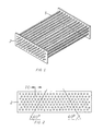
- the basic unit in the MTS heat exchanger is the MTS sub-assembly as illustrated in Fig.1. It consists of typically eight rows of microtubes 1 with typically 40 to 200 microtubes in each row.
- the microtubes are diffusion welded into precision MTS header strips 2 at each end.
- the diffusion welding is accomplished by using ultra precision, diamond- die-reduced, laser welded hard drawn tubing for the microtubes, and precisely machining the holes in the annealed header strip to a size at least 0.3% smaller but not more than 5% smaller than the tubing outside diameter.
- a combination of techniques may be required to produce the precision holes in the header strips, including feinblanking, electrochemical machining, and reaming.
- the diffusion welds are accomplished by ( 1 ) insuring that the tubes and holes have thoroughly cleaned, oxide-free surfaces prior to assembly, (2) maintaining a minimum of 0.3% interference press fit, (3) heating the sub-assembly in an inert atmosphere or vacuum to a temperature of approximately 80% of the absolute melting temperature of the tube or header strip alloy, whichever is lower.
- Fig 2 illustrates the recommended HCP (hexagonal close pack) hole pattern for the MTS header strip 2.
- the distance between rows is equal to 0.866 times the distance between tube centers, TC, which is generally about 1.3 to 2.8 times the O.D. of the sample tubes 1.
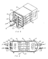
- Fig 3 illustrates the basic counterflow MTS module. It includes a semi-cylindrical cap 3 welded to each header strip. Care is taken to assure that the header strip 2 is no wider than is necessary to accomodate the microtubes 1 and the relatively thin walled cap 3 so that the MTS modules may be mounted closely in parallel. Tube-side manifold ports 4 are provided on each cap 3. A cage 5 closely surrounds the MTS sub-assembly, except near each header strip, forcing shell-side fluid 6 to enter around the periphery of the MTS sub-assembly near one end and to exit in like fashion at the other end. Tube-side fluid 7 enters the tube-side manifold ports 4 at the end at which the shell-side fluid exits, and it exits in like manner at the opposite end.
- Fig 5 illustrates the parallel manifolding of several MTS modules to form an MTS block.
- Individual fluid ports 4 are connected to a tube-side manifold 10 at each end.
- the manifold cages 11 in cooperation with the MTS module cages 5 form the shell-side sealed region.
- Tube-side fluid may enter at tube-side manifold port 12 while shell-side fluid may exit at manifold cage port 1 3.
- the MTS modules are supported by the headers, with adequate clearance space between the adjacent caps to permit the required shell-side flow 6 between caps with acceptable pressure drop.
- Typical MTS blocks may include four to fifteen MTS modules in parallel, and typical high power installations may include hundreds of such MTS blocks further manifolding in parallel.
- Fig 6 depicts an MTS block mounted inside a pressure vessel 14 forming an MTS tank for applications requiring high shell-side pressures.
- Pressure equalizing vents 1 5 are required to equalize mean static pressure components on the flat surface of the MTS cages 5 and manifold cages 11.
- the dynamic pressure components arising from the shell-side fluid pressure drop through the MTS block must be kept relatively small to prevent excessive deflection of the flat surfaces.
- Expansion joints 16 are required at one end to relieve axial thermal stresses.
- Suitable sealing flanges 17 and 18 are provided to permit convenient assembly of the containment vessel 14 and adequate sealing around the ports 1 2 and 13.
- Suitable radial support for the MTS block within the vessel is required at the end which includes the expansion joints 16.
Landscapes
- Engineering & Computer Science (AREA)
- Physics & Mathematics (AREA)
- Thermal Sciences (AREA)
- Mechanical Engineering (AREA)
- General Engineering & Computer Science (AREA)
- Geometry (AREA)
- Heat-Exchange Devices With Radiators And Conduit Assemblies (AREA)
- Details Of Heat-Exchange And Heat-Transfer (AREA)
Applications Claiming Priority (2)
| Application Number | Priority Date | Filing Date | Title |
|---|---|---|---|
| US700125 | 1985-02-11 | ||
| US06/700,125 US4676305A (en) | 1985-02-11 | 1985-02-11 | Microtube-strip heat exchanger |
Publications (2)
| Publication Number | Publication Date |
|---|---|
| EP0191602A2 true EP0191602A2 (de) | 1986-08-20 |
| EP0191602A3 EP0191602A3 (de) | 1986-11-26 |
Family
ID=24812296
Family Applications (1)
| Application Number | Title | Priority Date | Filing Date |
|---|---|---|---|
| EP86300807A Withdrawn EP0191602A3 (de) | 1985-02-11 | 1986-02-06 | Mikroröhren-Wärmetauscher mit dünnen Endplatten |
Country Status (5)
| Country | Link |
|---|---|
| US (1) | US4676305A (de) |
| EP (1) | EP0191602A3 (de) |
| JP (1) | JPS61190287A (de) |
| AU (1) | AU584979B2 (de) |
| CA (1) | CA1263113A (de) |
Cited By (8)
| Publication number | Priority date | Publication date | Assignee | Title |
|---|---|---|---|---|
| WO1992004233A1 (en) * | 1990-09-06 | 1992-03-19 | Doty Scientific, Inc. | Microtube array space radiator |
| FR2936179A1 (fr) * | 2008-09-23 | 2010-03-26 | Commissariat Energie Atomique | Procedede fabrication d'un systeme d'echangeur de chaleur, de preference du type echangeur/reacteur. |
| CN102401602A (zh) * | 2011-11-24 | 2012-04-04 | 无锡市鑫盛换热器制造有限公司 | 一种防热裂型换热器 |
| US8177932B2 (en) | 2009-02-27 | 2012-05-15 | International Mezzo Technologies, Inc. | Method for manufacturing a micro tube heat exchanger |
| GB2511664A (en) * | 2011-10-18 | 2014-09-10 | Cummins Generator Technologies | Housing for electrical machines |
| EP3514468A1 (de) * | 2018-01-18 | 2019-07-24 | United Technologies Corporation | Hybrider generativ gefertigter wärmetauscher mit rohren |
| US11519670B2 (en) | 2020-02-11 | 2022-12-06 | Airborne ECS, LLC | Microtube heat exchanger devices, systems and methods |
| US12416453B1 (en) | 2021-07-22 | 2025-09-16 | Intergalactic Spaceworx, LLC | Heat exchange header with refrigerant distribution by capillary wicking porous insert |
Families Citing this family (38)
| Publication number | Priority date | Publication date | Assignee | Title |
|---|---|---|---|---|
| US4844151A (en) * | 1986-12-23 | 1989-07-04 | Sundstrand Corporation | Heat exchanger apparatus |
| US5000253A (en) * | 1988-03-31 | 1991-03-19 | Roy Komarnicki | Ventilating heat recovery system |
| US4928755A (en) * | 1988-05-31 | 1990-05-29 | Doty Scientific, Inc. | Microtube strip surface exchanger |
| US4896410A (en) * | 1988-07-29 | 1990-01-30 | Doty Scientific Inc. | Method of assembling tube arrays |
| US5202633A (en) * | 1990-11-01 | 1993-04-13 | Doty Scientific, Inc. | High temperature nmr sample spinner |
| JPH09280755A (ja) * | 1996-04-18 | 1997-10-31 | Sanden Corp | 多管式熱交換器 |
| DE10023949C1 (de) * | 2000-05-16 | 2001-11-22 | Bosch Gmbh Robert | Wärmetauscher, insbesondere Mikrostruktur-Wärmetauscher |
| US6736134B2 (en) * | 2001-09-05 | 2004-05-18 | The Boeing Company | Thin wall header for use in molten salt solar absorption panels |
| ES2263394B1 (es) * | 2006-02-01 | 2007-11-16 | Sener, Ingenieria Y Sistemas, S.A. | Colector de seccion transversal variable y pared delgada para paneles de absorcion solar. |
| EP2195515A4 (de) * | 2007-10-12 | 2011-11-23 | Doty Scient Inc | Organischer hochtemperaturrankine-prozess mit zwei quellen mit gastrennungen |
| FR2909409B1 (fr) * | 2007-12-20 | 2013-03-29 | Inst Francais Du Petrole | Determination d'un profil thermique dans un puits en cours de forage |
| WO2009089460A2 (en) * | 2008-01-09 | 2009-07-16 | International Mezzo Technologies, Inc. | Corrugated micro tube heat exchanger |
| FR2926233B1 (fr) * | 2008-01-10 | 2010-08-13 | Air Liquide | Dispositif d'alimentation en gaz d'une machine de brasage ou etamage a la vague. |
| US20100193168A1 (en) * | 2009-02-02 | 2010-08-05 | Johnson Jr Alfred Leroy | Heat exchanger |
| KR101536989B1 (ko) | 2012-01-17 | 2015-07-16 | 알스톰 테크놀러지 리미티드 | 관류형 수평 증발기용 유동 제어 디바이스 및 방법 |
| EP2839213B1 (de) | 2012-01-17 | 2018-09-05 | General Electric Technology GmbH | Rohr- und blendenanordnung in einem horizontalen einmaldurchgangsverdampfer |
| DE102013100887A1 (de) * | 2013-01-29 | 2014-07-31 | Benteler Automobiltechnik Gmbh | Leitblech im Wärmetauscher |
| CN102922248B (zh) * | 2012-11-16 | 2014-11-05 | 扬州万福压力容器有限公司 | 需整体消应热处理管壳式换热器的加工工艺 |
| US20150136373A1 (en) * | 2013-11-21 | 2015-05-21 | Ronald John Mormann | Clustered Tubular Venting |
| US10006369B2 (en) | 2014-06-30 | 2018-06-26 | General Electric Company | Method and system for radial tubular duct heat exchangers |
| US9835380B2 (en) * | 2015-03-13 | 2017-12-05 | General Electric Company | Tube in cross-flow conduit heat exchanger |
| JP6357178B2 (ja) * | 2015-07-30 | 2018-07-11 | 株式会社デンソーエアクール | 熱交換器およびその製造方法 |
| US10060353B2 (en) * | 2015-08-14 | 2018-08-28 | United Technologies Corporation | Heat exchanger for cooled cooling air |
| EP3170541B1 (de) | 2015-11-18 | 2018-09-26 | Bosal Emission Control Systems NV | Kombinierter verdampfer und mischer |
| US10378835B2 (en) | 2016-03-25 | 2019-08-13 | Unison Industries, Llc | Heat exchanger with non-orthogonal perforations |
| WO2018213080A1 (en) * | 2017-05-17 | 2018-11-22 | Cummins Inc. | Waste heat recovery systems with heat exchangers |
| US11022375B2 (en) * | 2017-07-06 | 2021-06-01 | Divergent Technologies, Inc. | Apparatus and methods for additively manufacturing microtube heat exchangers |
| US20190033020A1 (en) * | 2017-07-27 | 2019-01-31 | United Technologies Corporation | Thin-walled heat exchanger with improved thermal transfer features |
| US12228349B2 (en) * | 2018-02-20 | 2025-02-18 | K&N Engineering, Inc. | Modular intercooler block |
| EP3801943B1 (de) * | 2018-06-01 | 2025-02-12 | Viant AS&O Holdings, LLC | Verbundrohranordnungen, dünnwandige rohre und verfahren zu ihrer herstellung |
| US11448467B1 (en) | 2018-09-28 | 2022-09-20 | Clean Energy Systems, Inc. | Micro-tube metal matrix heat exchanger and method of manufacture |
| CN110017720B (zh) * | 2019-03-29 | 2023-12-26 | 江门市东联热工设备有限公司 | 铆钉安装方法、铆钉安装结构及壁挂炉用钎焊式换热器 |
| US11859921B1 (en) * | 2020-02-29 | 2024-01-02 | International Mezzo Technologies, Inc. | Microtube heat exchanger |
| US20230234129A1 (en) * | 2022-01-25 | 2023-07-27 | Divergent Technologies, Inc. | Structurally integrated heat-exchangers |
| US12516895B2 (en) | 2022-02-16 | 2026-01-06 | Blue Box Air, Llc | Apparatus and methods for self-cleaning and maintaining HVAC heat transfer coils |
| US20240068750A1 (en) * | 2022-08-24 | 2024-02-29 | Blue Box Air, Llc | Closed loop, modular and self-cleaning hvac system |
| US12296293B2 (en) | 2022-09-27 | 2025-05-13 | Blue Box Air, Llc | Method and system for automated cleaning of filter wall for HVAC systems |
| US12259194B2 (en) | 2023-07-10 | 2025-03-25 | General Electric Company | Thermal management system |
Family Cites Families (21)
| Publication number | Priority date | Publication date | Assignee | Title |
|---|---|---|---|---|
| US2298996A (en) * | 1941-04-22 | 1942-10-13 | Clifford Mfg Co | Heat exchange apparatus |
| US2537024A (en) * | 1946-12-02 | 1951-01-09 | Thomas J Bay | Heat exchanger finned tube |
| FR1130461A (fr) * | 1951-01-16 | 1957-02-06 | Turbine à gaz perfectionnée et son procédé de construction | |
| DE965803C (de) * | 1954-09-11 | 1957-06-19 | Henschel & Sohn G M B H | Gasturbine mit kleinem eingebautem Waermeaustauscher |
| US2907644A (en) * | 1954-12-06 | 1959-10-06 | Standard Oil Co California | Chemical reactor |
| US2948517A (en) * | 1956-01-05 | 1960-08-09 | Martin Co | Tube bundle assembly |
| US3269459A (en) * | 1963-03-12 | 1966-08-30 | Popovitch Dragolyoub | Extensive surface heat exchanger |
| GB1141102A (en) * | 1966-04-01 | 1969-01-29 | Ass Elect Ind | Improvements in heat exchangers |
| US3526274A (en) * | 1968-06-04 | 1970-09-01 | Du Pont | Cross flow box cooler unit |
| DE2120544A1 (de) * | 1971-04-27 | 1972-11-16 | Gutehoffnungshütte Sterkrade AG, 4200 Oberhausen | Wärmeaustauscher |
| US3782457A (en) * | 1971-10-26 | 1974-01-01 | Rohr Corp | Recuperator and method of making |
| US4098852A (en) * | 1972-07-04 | 1978-07-04 | Rhone-Poulenc, S.A. | Process for carring out a gas/liquid heat-exchange |
| US3849854A (en) * | 1973-09-24 | 1974-11-26 | Emhart Corp | Method for making evaporator or condenser unit |
| FR2264620B1 (de) * | 1974-03-19 | 1976-12-17 | Chausson Usines Sa | |
| DE2422168C2 (de) * | 1974-05-08 | 1982-10-21 | Lev Nikolaevič Artemov | Wärmeaustauscher |
| DE2637169A1 (de) * | 1976-08-18 | 1978-02-23 | Bayer Ag | Verfahren zur thermischen reinigung von abluft |
| US4253516A (en) * | 1978-06-22 | 1981-03-03 | Westinghouse Electric Corp. | Modular heat exchanger |
| JPS5577080U (de) * | 1978-11-21 | 1980-05-27 | ||
| JPS6032553B2 (ja) * | 1980-02-15 | 1985-07-29 | 新日本製鐵株式会社 | 物体の接合法 |
| US4495987A (en) * | 1983-02-18 | 1985-01-29 | Occidental Research Corporation | Tube and tube sheet assembly |
| US4528733A (en) * | 1983-07-25 | 1985-07-16 | United Aircraft Products, Inc. | Method of making tubular heat exchangers |
-
1985
- 1985-02-11 US US06/700,125 patent/US4676305A/en not_active Ceased
-
1986
- 1986-02-06 EP EP86300807A patent/EP0191602A3/de not_active Withdrawn
- 1986-02-07 CA CA000501368A patent/CA1263113A/en not_active Expired
- 1986-02-10 AU AU53339/86A patent/AU584979B2/en not_active Ceased
- 1986-02-10 JP JP61026074A patent/JPS61190287A/ja active Granted
Cited By (11)
| Publication number | Priority date | Publication date | Assignee | Title |
|---|---|---|---|---|
| WO1992004233A1 (en) * | 1990-09-06 | 1992-03-19 | Doty Scientific, Inc. | Microtube array space radiator |
| US5267605A (en) * | 1990-09-06 | 1993-12-07 | Doty Scientific, Inc. | Microtube array space radiator |
| FR2936179A1 (fr) * | 2008-09-23 | 2010-03-26 | Commissariat Energie Atomique | Procedede fabrication d'un systeme d'echangeur de chaleur, de preference du type echangeur/reacteur. |
| WO2010034692A1 (fr) * | 2008-09-23 | 2010-04-01 | Commissariat A L'energie Atomique | Procede de fabrication d'un systeme d'echangeur de chaleur, de preference du type echangeur/reacteur |
| US8468697B2 (en) | 2008-09-23 | 2013-06-25 | Commissariat a l'Energie Atomique et aux Energiest Alternatives | Method for producing a heat exchanger system, preferably of the exchanger/reactor type |
| US8177932B2 (en) | 2009-02-27 | 2012-05-15 | International Mezzo Technologies, Inc. | Method for manufacturing a micro tube heat exchanger |
| GB2511664A (en) * | 2011-10-18 | 2014-09-10 | Cummins Generator Technologies | Housing for electrical machines |
| CN102401602A (zh) * | 2011-11-24 | 2012-04-04 | 无锡市鑫盛换热器制造有限公司 | 一种防热裂型换热器 |
| EP3514468A1 (de) * | 2018-01-18 | 2019-07-24 | United Technologies Corporation | Hybrider generativ gefertigter wärmetauscher mit rohren |
| US11519670B2 (en) | 2020-02-11 | 2022-12-06 | Airborne ECS, LLC | Microtube heat exchanger devices, systems and methods |
| US12416453B1 (en) | 2021-07-22 | 2025-09-16 | Intergalactic Spaceworx, LLC | Heat exchange header with refrigerant distribution by capillary wicking porous insert |
Also Published As
| Publication number | Publication date |
|---|---|
| US4676305A (en) | 1987-06-30 |
| EP0191602A3 (de) | 1986-11-26 |
| CA1263113A (en) | 1989-11-21 |
| JPS61190287A (ja) | 1986-08-23 |
| AU584979B2 (en) | 1989-06-08 |
| JPH0461278B2 (de) | 1992-09-30 |
| AU5333986A (en) | 1986-08-14 |
Similar Documents
| Publication | Publication Date | Title |
|---|---|---|
| EP0191602A2 (de) | Mikroröhren-Wärmetauscher mit dünnen Endplatten | |
| USRE33528E (en) | Microtube-strip heat exchanger | |
| Shah | Advances in science and technology of compact heat exchangers | |
| US5490559A (en) | Heat exchanger with finned partition walls | |
| US5538077A (en) | In tank oil cooler | |
| US8371365B2 (en) | Heat exchange device and method for manufacture | |
| US20050217837A1 (en) | Compact counterflow heat exchanger | |
| EP0212878A1 (de) | Kreuzstromplattenwärmetauscher | |
| EP0577616B1 (de) | Waermetauscher | |
| US4326582A (en) | Single element tube row heat exchanger | |
| CN109642779B (zh) | 通道将均匀流量分布区域和流体分岔区域集成为入口的板式热交换器模块 | |
| Kesseli et al. | Micro, industrial, and advanced gas turbines employing recuperators | |
| US5758718A (en) | Plate heat exchanger | |
| US4928755A (en) | Microtube strip surface exchanger | |
| US4134195A (en) | Method of manifold construction for formed tube-sheet heat exchanger and structure formed thereby | |
| US6675882B1 (en) | Apparatus and method for manufacturing one piece flat sides extruded product | |
| US6886629B2 (en) | Plate heat exchanger | |
| CN101454559B (zh) | 热交换器 | |
| CN114683013A (zh) | 一种铝合金微通道热交换器的加工方法 | |
| CN113606967B (zh) | 一种高压微通道换热器及其制造方法 | |
| EP0612396B1 (de) | Ölkühler in einem tank | |
| JP3051630B2 (ja) | プレートフィン型熱交換器 | |
| David Doty et al. | The microtube strip heat exchanger | |
| EP1331462A2 (de) | Wärmetauscher für Kraftfahrzeug | |
| JPH07167580A (ja) | プレートフィン型熱交換器の操業方法 |
Legal Events
| Date | Code | Title | Description |
|---|---|---|---|
| PUAI | Public reference made under article 153(3) epc to a published international application that has entered the european phase |
Free format text: ORIGINAL CODE: 0009012 |
|
| AK | Designated contracting states |
Kind code of ref document: A2 Designated state(s): AT BE CH DE FR GB IT LI LU NL SE |
|
| PUAL | Search report despatched |
Free format text: ORIGINAL CODE: 0009013 |
|
| AK | Designated contracting states |
Kind code of ref document: A3 Designated state(s): AT BE CH DE FR GB IT LI LU NL SE |
|
| 17P | Request for examination filed |
Effective date: 19870525 |
|
| 17Q | First examination report despatched |
Effective date: 19880115 |
|
| STAA | Information on the status of an ep patent application or granted ep patent |
Free format text: STATUS: THE APPLICATION IS DEEMED TO BE WITHDRAWN |
|
| 18D | Application deemed to be withdrawn |
Effective date: 19931214 |
|
| APAF | Appeal reference modified |
Free format text: ORIGINAL CODE: EPIDOSCREFNE |