EP0191602A2 - Microtube strip (MTS) heat exchanger - Google Patents
Microtube strip (MTS) heat exchanger Download PDFInfo
- Publication number
- EP0191602A2 EP0191602A2 EP86300807A EP86300807A EP0191602A2 EP 0191602 A2 EP0191602 A2 EP 0191602A2 EP 86300807 A EP86300807 A EP 86300807A EP 86300807 A EP86300807 A EP 86300807A EP 0191602 A2 EP0191602 A2 EP 0191602A2
- Authority
- EP
- European Patent Office
- Prior art keywords
- mts
- module
- heat exchanger
- microtubes
- tube
- Prior art date
- Legal status (The legal status is an assumption and is not a legal conclusion. Google has not performed a legal analysis and makes no representation as to the accuracy of the status listed.)
- Withdrawn
Links
Images

Classifications
-
- F—MECHANICAL ENGINEERING; LIGHTING; HEATING; WEAPONS; BLASTING
- F28—HEAT EXCHANGE IN GENERAL
- F28F—DETAILS OF HEAT-EXCHANGE AND HEAT-TRANSFER APPARATUS, OF GENERAL APPLICATION
- F28F9/00—Casings; Header boxes; Auxiliary supports for elements; Auxiliary members within casings
- F28F9/26—Arrangements for connecting different sections of heat-exchange elements, e.g. of radiators
-
- F—MECHANICAL ENGINEERING; LIGHTING; HEATING; WEAPONS; BLASTING
- F28—HEAT EXCHANGE IN GENERAL
- F28D—HEAT-EXCHANGE APPARATUS, NOT PROVIDED FOR IN ANOTHER SUBCLASS, IN WHICH THE HEAT-EXCHANGE MEDIA DO NOT COME INTO DIRECT CONTACT
- F28D7/00—Heat-exchange apparatus having stationary tubular conduit assemblies for both heat-exchange media, the media being in contact with different sides of a conduit wall
- F28D7/16—Heat-exchange apparatus having stationary tubular conduit assemblies for both heat-exchange media, the media being in contact with different sides of a conduit wall the conduits being arranged in parallel spaced relation
- F28D7/163—Heat-exchange apparatus having stationary tubular conduit assemblies for both heat-exchange media, the media being in contact with different sides of a conduit wall the conduits being arranged in parallel spaced relation with conduit assemblies having a particular shape, e.g. square or annular; with assemblies of conduits having different geometrical features; with multiple groups of conduits connected in series or parallel and arranged inside common casing
- F28D7/1653—Heat-exchange apparatus having stationary tubular conduit assemblies for both heat-exchange media, the media being in contact with different sides of a conduit wall the conduits being arranged in parallel spaced relation with conduit assemblies having a particular shape, e.g. square or annular; with assemblies of conduits having different geometrical features; with multiple groups of conduits connected in series or parallel and arranged inside common casing the conduit assemblies having a square or rectangular shape
-
- F—MECHANICAL ENGINEERING; LIGHTING; HEATING; WEAPONS; BLASTING
- F28—HEAT EXCHANGE IN GENERAL
- F28F—DETAILS OF HEAT-EXCHANGE AND HEAT-TRANSFER APPARATUS, OF GENERAL APPLICATION
- F28F9/00—Casings; Header boxes; Auxiliary supports for elements; Auxiliary members within casings
- F28F9/007—Auxiliary supports for elements
- F28F9/013—Auxiliary supports for elements for tubes or tube-assemblies
-
- F—MECHANICAL ENGINEERING; LIGHTING; HEATING; WEAPONS; BLASTING
- F28—HEAT EXCHANGE IN GENERAL
- F28F—DETAILS OF HEAT-EXCHANGE AND HEAT-TRANSFER APPARATUS, OF GENERAL APPLICATION
- F28F9/00—Casings; Header boxes; Auxiliary supports for elements; Auxiliary members within casings
- F28F9/02—Header boxes; End plates
- F28F9/04—Arrangements for sealing elements into header boxes or end plates
- F28F9/16—Arrangements for sealing elements into header boxes or end plates by permanent joints, e.g. by rolling
- F28F9/18—Arrangements for sealing elements into header boxes or end plates by permanent joints, e.g. by rolling by welding
-
- F—MECHANICAL ENGINEERING; LIGHTING; HEATING; WEAPONS; BLASTING
- F28—HEAT EXCHANGE IN GENERAL
- F28F—DETAILS OF HEAT-EXCHANGE AND HEAT-TRANSFER APPARATUS, OF GENERAL APPLICATION
- F28F2225/00—Reinforcing means
- F28F2225/04—Reinforcing means for conduits
-
- F—MECHANICAL ENGINEERING; LIGHTING; HEATING; WEAPONS; BLASTING
- F28—HEAT EXCHANGE IN GENERAL
- F28F—DETAILS OF HEAT-EXCHANGE AND HEAT-TRANSFER APPARATUS, OF GENERAL APPLICATION
- F28F2260/00—Heat exchangers or heat exchange elements having special size, e.g. microstructures
- F28F2260/02—Heat exchangers or heat exchange elements having special size, e.g. microstructures having microchannels
Definitions
- the field of this invention is heat exchangers, and more particularly, counterflow, modular, shell-and-tube-type exchangers for single phase fluids with no heat transfer augmentation means.
- Jabsen et aI in patent 4,289,196 and Culver in patent 4 ,098,329 employ unique heading and manifolding systems in attempts to achieve higher power densities in modular systems.
- Cunningham et al give attention to hot corrosive problems in patent 2,907,644.
- Lustenader recognizes the problem of axial conduction losses in patent 3,444,924, a problem obviously not understood by most heat exchanger design engineers.
- Corbitt et aI address the problem of vortex induced resonances in cross flow exchangers, #2,655,346, and solves it via strategic positioning of baffles.
- Scheidl uses a tube support grid to solve these problems in patent 3,941,188.
- patent 4,321,962 describes a solar energy heat exchanger and storage system
- patent 4, 4 56,882 describes a high-speed turbine-driven air-bearing-supported sample spinner.
- the microtube-strip (MTS) counterflow heat exchanger in the preferred embodiment consists of a number of small modules connected in parallel. Each module typically contains seven rows of one hundred tubes, each of 0.8mm outside diameter and 0.16m length. The tubes are metallurgically bonded to rectangular header tube strips at each end. Caps suitable for manifolding are welded over the ends. Means are provided to cause the shell-side fluid to flow in counterffow fashion over substan- tally all of the tube length, and suitable manifolds are provided to connect the modules in parallel. Power capacity per unit volume per unit temperature difference of the MTS exchanger exceeds that of prior art typical designs by a factor of ten to 1000. Power capacity per unit cost per unit temperature difference of the MTS exchanger may exceed that of prior art designs by a factor as large as 10 in some cases. Flow conditions in the microtubes are fully laminar and extremely subsonic.
- the tube-bundle heat exchanger with highly turbulent gas flowing through the tubes which are bathed in a constant temperature fluid.
- the conventional approach is to write the heat transfer coefficient in terms of the dimensionless Nusselt number, Nu. where d is the inside diameter (m) of the tubes and k is the thermal conductivity (W m -1 K -1 ) of the gas.
- the Nusselt number is then expressed in terms of two additional dimensionless groups, the Prandtl number, Pr, and the Reynolds number, Re.
- Cp is the constant pressure specific heat (J/KgK)
- ⁇ is the dynamic viscosity (Kg m -1 s -1 ).
- nL the total effective flow length
- the power, P p1 required to pump a fluid through the heat exchanger tubes is given by: where Ap is the pressure drop (Pa) through the exchanger, A r is the frontal fluid area (m 2 ), and v is the mean fluid velocity (m/s).
- the shell-side pumping power loss, P p2 , required to pump fluid around the tubes can be expressed by a similar equation: where the gas parameters ⁇ and v now refer to the external gas, and the coefficient f is the complicated function of tube diameter and spacing. For the standard hexagonal-close- pack pattern with the distance between tube centers equal to 1.4 times the tube outside diameter, f is approximately equal to 200.
- thermodynamic efficiency the axial thermal conduction power of the tube metal, P m .
- w is the wall thickness of the tubes (m)
- k m is the thermal conductivity of the tube metal (Wm -1 K -1 )
- TH is the mean temperature at the hot end
- T c is the mean temperature at the cold end.
- Reynolds numbers inside the microtubes for these optimized designs range from 25 to 400, compared to the more common prior art values of 10,000 to 100,000; and Nusseft numbers are less than 5, compared to the typical prior art values of 20 to 400. The result is fully developed laminar flow, tube side and shell side, and flow velocities below one tenth the speed of sound.
- the Tubing The Tubing.
- Current practice in tube-type counterflow generally uses induction-welded steel, copper, or aluminum tubes of about 10mm to 25mm diameter with lengths ranging from 1 m to 6m and wall thickness of about 1 mm to 3mm.
- recent advances in high speed laser welding technology now make it possible to produce very small stainless steel hypodermic tubing at very low production costs -less than $0.10 per meter. It is thus practical to consider the use of tubing with an inside diameter of less than 1 mm.
- Reducing the tubing diameter by a factor of 10 requires the length to be reduced by a factor ranging from 30 to 100 while the number of tubes is increased by a similar factor in order to maintain the same heat exchange power and pumping power loss.
- the total volume of the heat exchanger is likewise reduced.
- the maximum internal pressure rating of the heat exchanger will probably be increased due to an increase in the relative wall thickness.
- the maximum practical tube length for high-modulus, high strength alloys such as strain-hardened stainless steel or precipitation-hardened superalloys is about 300 times the outside diameter of the tubes, while the maximum practical length for copper or aluminum tubes is about half that amount.
- the braze metal is plated onto the inside of the holes and onto the outside of the tubes prior to assembly. After assembly, the complete module is heated in vacuum or inert atmosphere to the liquidus temperature of the braze metal. This method is not suited for very high temperature exchangers.
- Diffusion welding can be accomplished if the tube diameter and hole size can be held to very tight tolerances.
- the use of hardened tubes and annealed tube strips then makes it possible to press the tubes into slightly undersized holes. With proper attention to surface quality and a minimum of 0.3% interference press fit, a strong metallurgical bond can be formed simply by heating the assembly to about 0.8 times the absolute melting temperature (K). This method is suitable for the highest temperatures and all alloys.
- Thermal Response Time in many applications, particularly in the case of mobile gas turbines, fast response times are necessary for efficient operation.
- a typical 2000 KW gas turbine may have a mechanical response time of one minute, but the thermal response time of the heat exchangers incorporated into the system may be ten hours.
- Increasing the power-to-mass ratio of the heat exchanger by the amount possible with the MTS design could reduce the thermal time constant to less than one minute.
- Such a dramatic reduction in mass and thermal time constant opens up many new applications in all areas of transportation -especially aerospace.
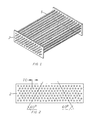
- the basic unit in the MTS heat exchanger is the MTS sub-assembly as illustrated in Fig.1. It consists of typically eight rows of microtubes 1 with typically 40 to 200 microtubes in each row.
- the microtubes are diffusion welded into precision MTS header strips 2 at each end.
- the diffusion welding is accomplished by using ultra precision, diamond- die-reduced, laser welded hard drawn tubing for the microtubes, and precisely machining the holes in the annealed header strip to a size at least 0.3% smaller but not more than 5% smaller than the tubing outside diameter.
- a combination of techniques may be required to produce the precision holes in the header strips, including feinblanking, electrochemical machining, and reaming.
- the diffusion welds are accomplished by ( 1 ) insuring that the tubes and holes have thoroughly cleaned, oxide-free surfaces prior to assembly, (2) maintaining a minimum of 0.3% interference press fit, (3) heating the sub-assembly in an inert atmosphere or vacuum to a temperature of approximately 80% of the absolute melting temperature of the tube or header strip alloy, whichever is lower.
- Fig 2 illustrates the recommended HCP (hexagonal close pack) hole pattern for the MTS header strip 2.
- the distance between rows is equal to 0.866 times the distance between tube centers, TC, which is generally about 1.3 to 2.8 times the O.D. of the sample tubes 1.
- Fig 3 illustrates the basic counterflow MTS module. It includes a semi-cylindrical cap 3 welded to each header strip. Care is taken to assure that the header strip 2 is no wider than is necessary to accomodate the microtubes 1 and the relatively thin walled cap 3 so that the MTS modules may be mounted closely in parallel. Tube-side manifold ports 4 are provided on each cap 3. A cage 5 closely surrounds the MTS sub-assembly, except near each header strip, forcing shell-side fluid 6 to enter around the periphery of the MTS sub-assembly near one end and to exit in like fashion at the other end. Tube-side fluid 7 enters the tube-side manifold ports 4 at the end at which the shell-side fluid exits, and it exits in like manner at the opposite end.
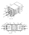
- Fig 5 illustrates the parallel manifolding of several MTS modules to form an MTS block.
- Individual fluid ports 4 are connected to a tube-side manifold 10 at each end.
- the manifold cages 11 in cooperation with the MTS module cages 5 form the shell-side sealed region.
- Tube-side fluid may enter at tube-side manifold port 12 while shell-side fluid may exit at manifold cage port 1 3.
- the MTS modules are supported by the headers, with adequate clearance space between the adjacent caps to permit the required shell-side flow 6 between caps with acceptable pressure drop.
- Typical MTS blocks may include four to fifteen MTS modules in parallel, and typical high power installations may include hundreds of such MTS blocks further manifolding in parallel.
- Fig 6 depicts an MTS block mounted inside a pressure vessel 14 forming an MTS tank for applications requiring high shell-side pressures.
- Pressure equalizing vents 1 5 are required to equalize mean static pressure components on the flat surface of the MTS cages 5 and manifold cages 11.
- the dynamic pressure components arising from the shell-side fluid pressure drop through the MTS block must be kept relatively small to prevent excessive deflection of the flat surfaces.
- Expansion joints 16 are required at one end to relieve axial thermal stresses.
- Suitable sealing flanges 17 and 18 are provided to permit convenient assembly of the containment vessel 14 and adequate sealing around the ports 1 2 and 13.
- Suitable radial support for the MTS block within the vessel is required at the end which includes the expansion joints 16.
Landscapes
- Engineering & Computer Science (AREA)
- Physics & Mathematics (AREA)
- Thermal Sciences (AREA)
- Mechanical Engineering (AREA)
- General Engineering & Computer Science (AREA)
- Geometry (AREA)
- Heat-Exchange Devices With Radiators And Conduit Assemblies (AREA)
- Details Of Heat-Exchange And Heat-Transfer (AREA)
Abstract
Description
- The field of this invention is heat exchangers, and more particularly, counterflow, modular, shell-and-tube-type exchangers for single phase fluids with no heat transfer augmentation means.
- The result of four decades of industrial and commercial interest in heat exchangers has been a proliferation of specialized devices and manufacturing techniques that offer some advantages in special applications. The present invention is based on a radical departure from conventional heat exchanger design guidelines in several distinct areas. As a result, the design differs in a number of ways, but the most significant innovative feature is the most subtle and is not apparent without a detailed theoretical explanation. This most important feature is its size. This change represents such radical departures from conventional practice in typical Nusselt and Reynolds numbers as to make reference to prior art of limited value. Nonetheless, for reference value and completeness, a brief synopsis of the prior art is presented by reference to various U.S. Patents.
- Numerous examples of modular, counter-flow shell and tube exchangers can be found in the patent literature, one of the earlier examples being Rossi's bi-directional flow design, #2,839,276, with its advantages of reduced thermal stresses. A more typical recent design is that of Baumgaert- ner et ai, #4,221,262, which offers some construction advantages over earlier designs due to the reduced complexity of its basic modutes. Quite atypical and impractical but of relevance on the account of general system appearance is Giardina's patent 4,253,516 with its huge box-car sized modules.
- Jabsen et aI in patent 4,289,196 and Culver in patent 4,098,329 employ unique heading and manifolding systems in attempts to achieve higher power densities in modular systems. Cunningham et al give attention to hot corrosive problems in patent 2,907,644. Lustenader recognizes the problem of axial conduction losses in patent 3,444,924, a problem obviously not understood by most heat exchanger design engineers.
- Corbitt et aI address the problem of vortex induced resonances in cross flow exchangers, #2,655,346, and solves it via strategic positioning of baffles. Scheidl uses a tube support grid to solve these problems in patent 3,941,188.
- Bay, #2,537,024, and Malewicz, #3,452,814, give several examples of heat flow augmentation, which is easily shown to be of negative value in a gas-gas heat exchanger optimized according to the present invention.
- Various well-known joining techniques include Cottone and Sapersteine's use of special braze alloys, #4,274,483, Olsson and Wilson's cold pressure welding, #4,237,971, Hardwick's explosive welding, #3,717,925, Brif and Brifs expanded tubes, #4,239,713, and the related technique of Yoshitomi et al, #4,142,581. More closely related to the diffusion technique of the present invention is the press-fit method of Nonnenmann et al, #4,159,741, and the compression method of Takayasu, #3,922,768. However, these techniques as described fall short of producing a high integrity metallurgical bond.
- Frei's patent 4,295,522, employing glass tubes and silicone casting resins, shows a striking resemblence from a non-scaled perspective between his basic tube assembly modules and the present invention. Furthermore, the tube sizes employed therein also show progressive design traits, being about 6mm in diameter rather than the customary 1.5cm to 2.5cm employed in all other above referenced patents. However, Frei's design, aside from temperature and pressure limitations imposed by the choice of materials, suffers from the inefficiencies inherent in a cross-flow design, as necessitated by his manifolding scheme.
- The use of small diameter tubes -O.D. less than about 3mm -has been predominately limited to two-phase cross- flow systems. Early examples may be found in aircraft oil- coolers such as that by Anderson, patent 2,449,922, and the later art. The only apparent application involving the use of tubes under 1 mm O.D. is that of Christen et al, #4,098,852, which employs osmotic or ultrafiltering polymeric tubes and vaporizing liquids. Christen's patent also utilizes the shortest tubes found in the prior art in counter- flow exchangers, such length being only about 0.6m, compared to the more typical length of about 5m. Roma's patent '4,030,540 is cited as a typical example of prior art design guidelines that often resulted in such unsound objectives as attempting to maximize tube length, whereas the correct objective is always to minimize tube length while satisfying several additional criteria.
- Some useful related theoretical background materials may be found in two of my earlier patents, although these inventions are quite remote from the present invention: patent 4,321,962 describes a solar energy heat exchanger and storage system; and patent 4,456,882 describes a high-speed turbine-driven air-bearing-supported sample spinner.
- The present invention, the microtube-strip (MTS) counterflow heat exchanger, in the preferred embodiment consists of a number of small modules connected in parallel. Each module typically contains seven rows of one hundred tubes, each of 0.8mm outside diameter and 0.16m length. The tubes are metallurgically bonded to rectangular header tube strips at each end. Caps suitable for manifolding are welded over the ends. Means are provided to cause the shell-side fluid to flow in counterffow fashion over substan- tally all of the tube length, and suitable manifolds are provided to connect the modules in parallel. Power capacity per unit volume per unit temperature difference of the MTS exchanger exceeds that of prior art typical designs by a factor of ten to 1000. Power capacity per unit cost per unit temperature difference of the MTS exchanger may exceed that of prior art designs by a factor as large as 10 in some cases. Flow conditions in the microtubes are fully laminar and extremely subsonic.
-
- Fig. 1 is an isometric drawing of an MTS sub-assembly.
- Fig. 2 is a plane section view of an MTS header.
- Fig. 3 is an isometric drawing of an MTS module.
- Fig. 4 illustrates two reinforcement techniques for MTS modules operating with high tube-side pressure.
- Fig. 5 is an isometric drawing of a plurality of MTS modules manifolded together in parallel to form an MTS block.
- Fig. 6 illustrates an MTS block enclosed in a pressurized vessel.
- The Heat Exchanoe Power. The usual approach to heat transfer problems is to begin with the following equation:

- Consider first, for example, the tube-bundle heat exchanger with highly turbulent gas flowing through the tubes, which are bathed in a constant temperature fluid. The conventional approach is to write the heat transfer coefficient in terms of the dimensionless Nusselt number, Nu.


- Now consider the case of a tube-type counterflow laminar-flow heat exchanger with center-to-center tube spacing equal to 1.4 times the outside diameter of the tubes and twice the inside diameter. Further assume that the thermal conductivity of the tube material is much greater than the thermal conductivity of the fluids. For this case, it can be shown that the heat exchange power is independent of the tube diameter, and is given by the following expression:

- From the above discussion it appears that there is little utility in evaluating a heat exchanger in terms of a heat exchange coefficient of dimensions Wm-2K-1 as is customary in the professional and patent literature. Rather, a more useful characterization is the total effective flow length, nL. By defining nL as the quotient of Ph and a generalized function of k, and k2, one arrives at a useful method of comparing diverse designs -including those which incorporate heat transfer augmentation means such as extended or roughened surfaces.
- Power Losses. The power, Pp1 required to pump a fluid through the heat exchanger tubes is given by:

- For simplicity, consider the case of laminar fluid flow through long, smooth tubes. This condition exists for Reynolds numbers, Re, below 2000. the pressure drop, Ap, in a fluid flowing through a tube under laminar conditions is given by:


- The shell-side pumping power loss, Pp2, required to pump fluid around the tubes can be expressed by a similar equation:

- In addition to the pumping power loss, there is another internal loss mechanism present in counterflow exchangers which may limit the thermodynamic efficiency: the axial thermal conduction power of the tube metal, Pm.

- Ootimization. The power available, Pi, from the input gas is:
- P1 = GCp (TH -Tc ), where Cp is the constant pressure specific heat (J/Kg K), and G is the mass flow rate (Kg/s) and is equal to pAfv. The waste heat, Po, is

- Accounting for the losses, the available heat exchange power, PE, is


- The above equations can now be solved for Tδ using the definition of mass flow rate and assuming w = d/3.

- This equation depends only on three geometric variables, n, L, and d , and is reasonably valid for tube-type counterflow laminar heat exchangers, subject to several above mentioned assumptions. One can now calculate the power losses and the available heat exchange power for a given set of thermodynamic and geometric conditions. The design can be optimized via the linear programming technique of maximizing an objective function, F c, such as the following:

- Alternatively one may choose as objective function Fvsuch that

- The Tubing. Current practice in tube-type counterflow generally uses induction-welded steel, copper, or aluminum tubes of about 10mm to 25mm diameter with lengths ranging from 1 m to 6m and wall thickness of about 1 mm to 3mm. However, recent advances in high speed laser welding technology now make it possible to produce very small stainless steel hypodermic tubing at very low production costs -less than $0.10 per meter. It is thus practical to consider the use of tubing with an inside diameter of less than 1 mm.
- Reducing the tubing diameter by a factor of 10 requires the length to be reduced by a factor ranging from 30 to 100 while the number of tubes is increased by a similar factor in order to maintain the same heat exchange power and pumping power loss. However, the total volume of the heat exchanger is likewise reduced. Furthermore, the maximum internal pressure rating of the heat exchanger will probably be increased due to an increase in the relative wall thickness.
- To facilitate rapid assembly of large numbers of small tubes, it is necessary to depart from the disc shaped tube header sheet normally used in counterflow exchangers and instead use a rectangular tube header sheet or strip. Furthermore, to minimize tube flexing and to reduce support requirements, it is also desirable to keep the tube length relatively short. This will also ensure that the buckling strength of the tubes is large enough to permit pressing them into the tube strip. Moreover, it will raise the transverse acoustic resonance modes of the tubes thereby making it more difficult to excite such resonances by turbulence.
- The maximum practical tube length for high-modulus, high strength alloys such as strain-hardened stainless steel or precipitation-hardened superalloys is about 300 times the outside diameter of the tubes, while the maximum practical length for copper or aluminum tubes is about half that amount. There are several additional reasons for preferring stainless steel or superalloys over the more common heat exchanger metals: (1) They have very low thermal conductivity which may make them easier to laser weld, but most importantly reduces the intemal-axial conduction loss mechanism, Pm, in the counterflow exchangers; (2) Their. high tensile strength allows higher working pressures; and - (3) Their corrosion and high temperature strength properties are essential in many applications.
- Weldino and Manifoldina. The key to the current invention is the recognition of the advantage of using small diameter tubing in very short lengths. Its implementation depends on technological breakthroughs in the asse,mbly, welding, and manifolding of these tubes. Since the tubes are very short, it is necessary to resort to narrow modules in order that counterflow conditions be established over the major portion of the tube length and also to reduce the inefficiencies due to non-uniform flow. While a cross-flow arrangement could be used to circumvent the above mentioned non-uniform flow problems, such an arrangement would greatly reduce the thermodynamic efficiency. The counterflow-serial-crossflow arrangement commonly used in large installations allows somewhat higher efficiency than the crossflow arrangement but at increased pumping losses. Hence, the most satisfactory solution is that of narrow modules of four to twenty rows of tubes.
- The extremely small size of the tubes makes almost all types of conventional welding methods impractical, and the extremely large number of tubes eliminates most types of individual tube welding techniques, probably including automated electron beam and laser techniques because of process control problems arising from thermal expansion during the welding operations. Two viable options for the tube-to-strip welds are fluxless brazing and diffusion welding. A wide variety of conventional welding techniques are suitable for the rest of the welds.
- In the fluxless brazing technique, the braze metal is plated onto the inside of the holes and onto the outside of the tubes prior to assembly. After assembly, the complete module is heated in vacuum or inert atmosphere to the liquidus temperature of the braze metal. This method is not suited for very high temperature exchangers.
- Diffusion welding can be accomplished if the tube diameter and hole size can be held to very tight tolerances. The use of hardened tubes and annealed tube strips then makes it possible to press the tubes into slightly undersized holes. With proper attention to surface quality and a minimum of 0.3% interference press fit, a strong metallurgical bond can be formed simply by heating the assembly to about 0.8 times the absolute melting temperature (K). This method is suitable for the highest temperatures and all alloys.
- Corrosion. In many cases, heat exchangers must operate in severely corrosive environments. Under these conditions, it is no longer theoretically possible to increase the power-to-volume ratio without limit. The current state-of-the- art in corrosion resistant alloys, such as Nimonic 81, limits the minimum wall thickness to about 50 microns for moderately corrosive environments and about 200 microns for severely corrosive environments. Although the tubes themselves are too small to make coatings or laminations practical with current technology, such measures may be applied to the tube strips and to the manifolds for economy of materials or to achieve combined high temperature strength and hot corrosion resistance.
- Thermal Response Time. in many applications, particularly in the case of mobile gas turbines, fast response times are necessary for efficient operation. Currently, a typical 2000 KW gas turbine may have a mechanical response time of one minute, but the thermal response time of the heat exchangers incorporated into the system may be ten hours. Increasing the power-to-mass ratio of the heat exchanger by the amount possible with the MTS design could reduce the thermal time constant to less than one minute. Such a dramatic reduction in mass and thermal time constant opens up many new applications in all areas of transportation -especially aerospace.
- High Pressure Aoolications. In many applications, for example, in recuperators used in closed cycle gas turbines, it is necessary to maintain both the internal (tube-side) and the external (shell-side) fluids at high pressure. The narrow width of the tube header strip makes this design well suited to high tube-side pressures. When high shell-side pressures are required, the entire heat exchanger must be enclosed in a pressurized containment vessel. The small size of the heat exchanger simplifies this task.
- The basic unit in the MTS heat exchanger is the MTS sub-assembly as illustrated in Fig.1. It consists of typically eight rows of microtubes 1 with typically 40 to 200 microtubes in each row. The microtubes are diffusion welded into precision MTS header strips 2 at each end. The diffusion welding is accomplished by using ultra precision, diamond- die-reduced, laser welded hard drawn tubing for the microtubes, and precisely machining the holes in the annealed header strip to a size at least 0.3% smaller but not more than 5% smaller than the tubing outside diameter. A combination of techniques may be required to produce the precision holes in the header strips, including feinblanking, electrochemical machining, and reaming. The diffusion welds are accomplished by (1) insuring that the tubes and holes have thoroughly cleaned, oxide-free surfaces prior to assembly, (2) maintaining a minimum of 0.3% interference press fit, (3) heating the sub-assembly in an inert atmosphere or vacuum to a temperature of approximately 80% of the absolute melting temperature of the tube or header strip alloy, whichever is lower.
- Fig 2 illustrates the recommended HCP (hexagonal close pack) hole pattern for the
MTS header strip 2. The distance between rows is equal to 0.866 times the distance between tube centers, TC, which is generally about 1.3 to 2.8 times the O.D. of the sample tubes 1. - Fig 3 illustrates the basic counterflow MTS module. It includes a
semi-cylindrical cap 3 welded to each header strip. Care is taken to assure that theheader strip 2 is no wider than is necessary to accomodate the microtubes 1 and the relatively thinwalled cap 3 so that the MTS modules may be mounted closely in parallel. Tube-side manifold ports 4 are provided on eachcap 3. Acage 5 closely surrounds the MTS sub-assembly, except near each header strip, forcing shell-side fluid 6 to enter around the periphery of the MTS sub-assembly near one end and to exit in like fashion at the other end. Tube-side fluid 7 enters the tube-side manifold ports 4 at the end at which the shell-side fluid exits, and it exits in like manner at the opposite end. - In certain applications, extremely high tube-side pressures, perhaps combined with very high temperatures, may require additional support of the
flat header strip 2, to prevent bowing of this surface. This additional support may be provided as shown in Fig 4 by diffusion welding areinforcement plate 8 similar to the header strip 2 a short distance from it Altematively, the required support may be provided by the microtubes 1 if they are supported in such a way to prevent their buckling. This may be accomplished by bonding, preferably by projection welding, stiffeningwires 9 crosswise between the rows of microtubes 1. By staggering or offsetting the location ofadjacent stiffening wires 9, the effect on fluid flow is generally made negligible. - Fig 5 illustrates the parallel manifolding of several MTS modules to form an MTS block. Individual fluid ports 4 are connected to a tube-
side manifold 10 at each end. Themanifold cages 11 in cooperation with theMTS module cages 5 form the shell-side sealed region. Tube-side fluid may enter at tube-side manifold port 12 while shell-side fluid may exit atmanifold cage port 13. The MTS modules are supported by the headers, with adequate clearance space between the adjacent caps to permit the required shell-side flow 6 between caps with acceptable pressure drop. Typical MTS blocks may include four to fifteen MTS modules in parallel, and typical high power installations may include hundreds of such MTS blocks further manifolding in parallel. - Fig 6 depicts an MTS block mounted inside a
pressure vessel 14 forming an MTS tank for applications requiring high shell-side pressures. Pressure equalizingvents 15 are required to equalize mean static pressure components on the flat surface of theMTS cages 5 andmanifold cages 11. The dynamic pressure components arising from the shell-side fluid pressure drop through the MTS block must be kept relatively small to prevent excessive deflection of the flat surfaces.Expansion joints 16 are required at one end to relieve axial thermal stresses.Suitable sealing flanges containment vessel 14 and adequate sealing around theports - Although this invention has been described herein with reference to specific embodiments, it will be recognised that changes and modifications may be made without departing from the spirit of the present invention. All such modifications and changes are intended to be included within the scope of the following claims.
Claims (10)
Applications Claiming Priority (2)
| Application Number | Priority Date | Filing Date | Title |
|---|---|---|---|
| US06/700,125 US4676305A (en) | 1985-02-11 | 1985-02-11 | Microtube-strip heat exchanger |
| US700125 | 1985-02-11 |
Publications (2)
| Publication Number | Publication Date |
|---|---|
| EP0191602A2 true EP0191602A2 (en) | 1986-08-20 |
| EP0191602A3 EP0191602A3 (en) | 1986-11-26 |
Family
ID=24812296
Family Applications (1)
| Application Number | Title | Priority Date | Filing Date |
|---|---|---|---|
| EP86300807A Withdrawn EP0191602A3 (en) | 1985-02-11 | 1986-02-06 | Microtube strip (mts) heat exchanger |
Country Status (5)
| Country | Link |
|---|---|
| US (1) | US4676305A (en) |
| EP (1) | EP0191602A3 (en) |
| JP (1) | JPS61190287A (en) |
| AU (1) | AU584979B2 (en) |
| CA (1) | CA1263113A (en) |
Cited By (8)
| Publication number | Priority date | Publication date | Assignee | Title |
|---|---|---|---|---|
| WO1992004233A1 (en) * | 1990-09-06 | 1992-03-19 | Doty Scientific, Inc. | Microtube array space radiator |
| FR2936179A1 (en) * | 2008-09-23 | 2010-03-26 | Commissariat Energie Atomique | METHOD FOR MANUFACTURING A HEAT EXCHANGER SYSTEM, PREFERABLY OF THE EXCHANGER / REACTOR TYPE |
| CN102401602A (en) * | 2011-11-24 | 2012-04-04 | 无锡市鑫盛换热器制造有限公司 | Heat-cracking-prevention type heat exchanger |
| US8177932B2 (en) | 2009-02-27 | 2012-05-15 | International Mezzo Technologies, Inc. | Method for manufacturing a micro tube heat exchanger |
| GB2511664A (en) * | 2011-10-18 | 2014-09-10 | Cummins Generator Technologies | Housing for electrical machines |
| EP3514468A1 (en) * | 2018-01-18 | 2019-07-24 | United Technologies Corporation | Hybrid additive manufactured heat exchanger with tubes |
| US11519670B2 (en) | 2020-02-11 | 2022-12-06 | Airborne ECS, LLC | Microtube heat exchanger devices, systems and methods |
| US12416453B1 (en) | 2021-07-22 | 2025-09-16 | Intergalactic Spaceworx, LLC | Heat exchange header with refrigerant distribution by capillary wicking porous insert |
Families Citing this family (38)
| Publication number | Priority date | Publication date | Assignee | Title |
|---|---|---|---|---|
| US4844151A (en) * | 1986-12-23 | 1989-07-04 | Sundstrand Corporation | Heat exchanger apparatus |
| US5000253A (en) * | 1988-03-31 | 1991-03-19 | Roy Komarnicki | Ventilating heat recovery system |
| US4928755A (en) * | 1988-05-31 | 1990-05-29 | Doty Scientific, Inc. | Microtube strip surface exchanger |
| US4896410A (en) * | 1988-07-29 | 1990-01-30 | Doty Scientific Inc. | Method of assembling tube arrays |
| US5202633A (en) * | 1990-11-01 | 1993-04-13 | Doty Scientific, Inc. | High temperature nmr sample spinner |
| JPH09280755A (en) * | 1996-04-18 | 1997-10-31 | Sanden Corp | Tubular heat exchanger |
| DE10023949C1 (en) * | 2000-05-16 | 2001-11-22 | Bosch Gmbh Robert | Heat exchangers, in particular microstructure heat exchangers |
| US6736134B2 (en) * | 2001-09-05 | 2004-05-18 | The Boeing Company | Thin wall header for use in molten salt solar absorption panels |
| ES2263394B1 (en) * | 2006-02-01 | 2007-11-16 | Sener, Ingenieria Y Sistemas, S.A. | VARIABLE CROSS SECTION COLLECTOR AND SLIM WALL FOR SOLAR ABSORPTION PANELS. |
| EP2195515A4 (en) * | 2007-10-12 | 2011-11-23 | Doty Scient Inc | High-temperature dual-source organic rankine cycle with gas separations |
| FR2909409B1 (en) * | 2007-12-20 | 2013-03-29 | Inst Francais Du Petrole | DETERMINING A THERMAL PROFILE IN A WELL DURING DRILLING |
| WO2009089460A2 (en) * | 2008-01-09 | 2009-07-16 | International Mezzo Technologies, Inc. | Corrugated micro tube heat exchanger |
| FR2926233B1 (en) * | 2008-01-10 | 2010-08-13 | Air Liquide | DEVICE FOR SUPPLYING GAS TO A SOLDERING MACHINE OR WINDING PLASTER. |
| US20100193168A1 (en) * | 2009-02-02 | 2010-08-05 | Johnson Jr Alfred Leroy | Heat exchanger |
| EP2839213B1 (en) * | 2012-01-17 | 2018-09-05 | General Electric Technology GmbH | Tube and baffle arrangement in a once-through horizontal evaporator |
| KR102049106B1 (en) | 2012-01-17 | 2019-11-27 | 제네럴 일렉트릭 테크놀러지 게엠베하 | Tube arrangement in a once-through horizontal evaporator |
| DE102013100887A1 (en) * | 2013-01-29 | 2014-07-31 | Benteler Automobiltechnik Gmbh | Guide plate in the heat exchanger |
| CN102922248B (en) * | 2012-11-16 | 2014-11-05 | 扬州万福压力容器有限公司 | Processing technique of shell-and-tube heat exchanger requiring whole stress-relief heat treatment |
| US20150136373A1 (en) * | 2013-11-21 | 2015-05-21 | Ronald John Mormann | Clustered Tubular Venting |
| US10006369B2 (en) | 2014-06-30 | 2018-06-26 | General Electric Company | Method and system for radial tubular duct heat exchangers |
| US9835380B2 (en) * | 2015-03-13 | 2017-12-05 | General Electric Company | Tube in cross-flow conduit heat exchanger |
| JP6357178B2 (en) * | 2015-07-30 | 2018-07-11 | 株式会社デンソーエアクール | Heat exchanger and manufacturing method thereof |
| US10060353B2 (en) * | 2015-08-14 | 2018-08-28 | United Technologies Corporation | Heat exchanger for cooled cooling air |
| US10465902B2 (en) | 2015-11-18 | 2019-11-05 | Bosal Emission Control Systems Nv | Combined evaporator and mixer |
| US10378835B2 (en) | 2016-03-25 | 2019-08-13 | Unison Industries, Llc | Heat exchanger with non-orthogonal perforations |
| US10968785B2 (en) * | 2017-05-17 | 2021-04-06 | Cummins Inc. | Waste heat recovery systems with heat exchangers |
| US11022375B2 (en) * | 2017-07-06 | 2021-06-01 | Divergent Technologies, Inc. | Apparatus and methods for additively manufacturing microtube heat exchangers |
| US20190033020A1 (en) * | 2017-07-27 | 2019-01-31 | United Technologies Corporation | Thin-walled heat exchanger with improved thermal transfer features |
| US12228349B2 (en) * | 2018-02-20 | 2025-02-18 | K&N Engineering, Inc. | Modular intercooler block |
| US11543066B2 (en) | 2018-06-01 | 2023-01-03 | Viant As&O Holdings Llc | Composite tube with a sacrificial layer for very thin wall heat exchangers |
| US11448467B1 (en) | 2018-09-28 | 2022-09-20 | Clean Energy Systems, Inc. | Micro-tube metal matrix heat exchanger and method of manufacture |
| CN110017720B (en) * | 2019-03-29 | 2023-12-26 | 江门市东联热工设备有限公司 | Rivet mounting method, rivet mounting structure and brazing type heat exchanger for wall-mounted furnace |
| US11859921B1 (en) * | 2020-02-29 | 2024-01-02 | International Mezzo Technologies, Inc. | Microtube heat exchanger |
| US20230234129A1 (en) * | 2022-01-25 | 2023-07-27 | Divergent Technologies, Inc. | Structurally integrated heat-exchangers |
| US12516895B2 (en) | 2022-02-16 | 2026-01-06 | Blue Box Air, Llc | Apparatus and methods for self-cleaning and maintaining HVAC heat transfer coils |
| US20240068750A1 (en) * | 2022-08-24 | 2024-02-29 | Blue Box Air, Llc | Closed loop, modular and self-cleaning hvac system |
| US12296293B2 (en) | 2022-09-27 | 2025-05-13 | Blue Box Air, Llc | Method and system for automated cleaning of filter wall for HVAC systems |
| US12259194B2 (en) | 2023-07-10 | 2025-03-25 | General Electric Company | Thermal management system |
Family Cites Families (21)
| Publication number | Priority date | Publication date | Assignee | Title |
|---|---|---|---|---|
| US2298996A (en) * | 1941-04-22 | 1942-10-13 | Clifford Mfg Co | Heat exchange apparatus |
| US2537024A (en) * | 1946-12-02 | 1951-01-09 | Thomas J Bay | Heat exchanger finned tube |
| FR1130461A (en) * | 1951-01-16 | 1957-02-06 | Improved gas turbine and method of construction | |
| DE965803C (en) * | 1954-09-11 | 1957-06-19 | Henschel & Sohn G M B H | Gas turbine with a small built-in heat exchanger |
| US2907644A (en) * | 1954-12-06 | 1959-10-06 | Standard Oil Co California | Chemical reactor |
| US2948517A (en) * | 1956-01-05 | 1960-08-09 | Martin Co | Tube bundle assembly |
| US3269459A (en) * | 1963-03-12 | 1966-08-30 | Popovitch Dragolyoub | Extensive surface heat exchanger |
| GB1141102A (en) * | 1966-04-01 | 1969-01-29 | Ass Elect Ind | Improvements in heat exchangers |
| US3526274A (en) * | 1968-06-04 | 1970-09-01 | Du Pont | Cross flow box cooler unit |
| DE2120544A1 (en) * | 1971-04-27 | 1972-11-16 | Gutehoffnungshütte Sterkrade AG, 4200 Oberhausen | Heat exchanger |
| US3782457A (en) * | 1971-10-26 | 1974-01-01 | Rohr Corp | Recuperator and method of making |
| US4098852A (en) * | 1972-07-04 | 1978-07-04 | Rhone-Poulenc, S.A. | Process for carring out a gas/liquid heat-exchange |
| US3849854A (en) * | 1973-09-24 | 1974-11-26 | Emhart Corp | Method for making evaporator or condenser unit |
| FR2264620B1 (en) * | 1974-03-19 | 1976-12-17 | Chausson Usines Sa | |
| DE2422168C2 (en) * | 1974-05-08 | 1982-10-21 | Lev Nikolaevič Artemov | Heat exchanger |
| DE2637169A1 (en) * | 1976-08-18 | 1978-02-23 | Bayer Ag | METHOD FOR THERMAL PURIFICATION OF EXHAUST AIR |
| US4253516A (en) * | 1978-06-22 | 1981-03-03 | Westinghouse Electric Corp. | Modular heat exchanger |
| JPS5577080U (en) * | 1978-11-21 | 1980-05-27 | ||
| JPS6032553B2 (en) * | 1980-02-15 | 1985-07-29 | 新日本製鐵株式会社 | How to join objects |
| US4495987A (en) * | 1983-02-18 | 1985-01-29 | Occidental Research Corporation | Tube and tube sheet assembly |
| US4528733A (en) * | 1983-07-25 | 1985-07-16 | United Aircraft Products, Inc. | Method of making tubular heat exchangers |
-
1985
- 1985-02-11 US US06/700,125 patent/US4676305A/en not_active Ceased
-
1986
- 1986-02-06 EP EP86300807A patent/EP0191602A3/en not_active Withdrawn
- 1986-02-07 CA CA000501368A patent/CA1263113A/en not_active Expired
- 1986-02-10 AU AU53339/86A patent/AU584979B2/en not_active Ceased
- 1986-02-10 JP JP61026074A patent/JPS61190287A/en active Granted
Cited By (11)
| Publication number | Priority date | Publication date | Assignee | Title |
|---|---|---|---|---|
| WO1992004233A1 (en) * | 1990-09-06 | 1992-03-19 | Doty Scientific, Inc. | Microtube array space radiator |
| US5267605A (en) * | 1990-09-06 | 1993-12-07 | Doty Scientific, Inc. | Microtube array space radiator |
| FR2936179A1 (en) * | 2008-09-23 | 2010-03-26 | Commissariat Energie Atomique | METHOD FOR MANUFACTURING A HEAT EXCHANGER SYSTEM, PREFERABLY OF THE EXCHANGER / REACTOR TYPE |
| WO2010034692A1 (en) * | 2008-09-23 | 2010-04-01 | Commissariat A L'energie Atomique | Method for making a heat exchanger system, preferably of the exchanger/reactor type |
| US8468697B2 (en) | 2008-09-23 | 2013-06-25 | Commissariat a l'Energie Atomique et aux Energiest Alternatives | Method for producing a heat exchanger system, preferably of the exchanger/reactor type |
| US8177932B2 (en) | 2009-02-27 | 2012-05-15 | International Mezzo Technologies, Inc. | Method for manufacturing a micro tube heat exchanger |
| GB2511664A (en) * | 2011-10-18 | 2014-09-10 | Cummins Generator Technologies | Housing for electrical machines |
| CN102401602A (en) * | 2011-11-24 | 2012-04-04 | 无锡市鑫盛换热器制造有限公司 | Heat-cracking-prevention type heat exchanger |
| EP3514468A1 (en) * | 2018-01-18 | 2019-07-24 | United Technologies Corporation | Hybrid additive manufactured heat exchanger with tubes |
| US11519670B2 (en) | 2020-02-11 | 2022-12-06 | Airborne ECS, LLC | Microtube heat exchanger devices, systems and methods |
| US12416453B1 (en) | 2021-07-22 | 2025-09-16 | Intergalactic Spaceworx, LLC | Heat exchange header with refrigerant distribution by capillary wicking porous insert |
Also Published As
| Publication number | Publication date |
|---|---|
| JPH0461278B2 (en) | 1992-09-30 |
| EP0191602A3 (en) | 1986-11-26 |
| US4676305A (en) | 1987-06-30 |
| CA1263113A (en) | 1989-11-21 |
| JPS61190287A (en) | 1986-08-23 |
| AU5333986A (en) | 1986-08-14 |
| AU584979B2 (en) | 1989-06-08 |
Similar Documents
| Publication | Publication Date | Title |
|---|---|---|
| EP0191602A2 (en) | Microtube strip (MTS) heat exchanger | |
| USRE33528E (en) | Microtube-strip heat exchanger | |
| Shah | Advances in science and technology of compact heat exchangers | |
| US6390185B1 (en) | Annular flow concentric tube recuperator | |
| CA1276009C (en) | Plate type heat exchanger | |
| US8371365B2 (en) | Heat exchange device and method for manufacture | |
| US20050217837A1 (en) | Compact counterflow heat exchanger | |
| EP0212878A1 (en) | Plate-type cross-flow heat exchanger | |
| EP0577616B1 (en) | Heat exchanger | |
| US4928755A (en) | Microtube strip surface exchanger | |
| US4326582A (en) | Single element tube row heat exchanger | |
| US6675882B1 (en) | Apparatus and method for manufacturing one piece flat sides extruded product | |
| US4134195A (en) | Method of manifold construction for formed tube-sheet heat exchanger and structure formed thereby | |
| US6886629B2 (en) | Plate heat exchanger | |
| CN101454559B (en) | Heat exchanger | |
| US6209629B1 (en) | Beaded plate for a heat exchanger and method of making same | |
| CN114683013A (en) | Processing method of aluminum alloy micro-channel heat exchanger | |
| CN118758098A (en) | A modular heat exchange system and a heat exchange network design method | |
| CN113606967B (en) | High-pressure micro-channel heat exchanger and manufacturing method thereof | |
| Thonon et al. | Compact heat exchanger technologies for the HTRs recuperator application | |
| JP3051630B2 (en) | Plate fin type heat exchanger | |
| WO1993010415A1 (en) | In tank oil cooler | |
| EP1331462A2 (en) | Automotive heat exchanger | |
| JPH07167580A (en) | Operating method of plate fin type heat exchanger | |
| CN116817646A (en) | Cross flow mixed type printed circuit board type heat exchanger |
Legal Events
| Date | Code | Title | Description |
|---|---|---|---|
| PUAI | Public reference made under article 153(3) epc to a published international application that has entered the european phase |
Free format text: ORIGINAL CODE: 0009012 |
|
| AK | Designated contracting states |
Kind code of ref document: A2 Designated state(s): AT BE CH DE FR GB IT LI LU NL SE |
|
| PUAL | Search report despatched |
Free format text: ORIGINAL CODE: 0009013 |
|
| AK | Designated contracting states |
Kind code of ref document: A3 Designated state(s): AT BE CH DE FR GB IT LI LU NL SE |
|
| 17P | Request for examination filed |
Effective date: 19870525 |
|
| 17Q | First examination report despatched |
Effective date: 19880115 |
|
| STAA | Information on the status of an ep patent application or granted ep patent |
Free format text: STATUS: THE APPLICATION IS DEEMED TO BE WITHDRAWN |
|
| 18D | Application deemed to be withdrawn |
Effective date: 19931214 |
|
| APAF | Appeal reference modified |
Free format text: ORIGINAL CODE: EPIDOSCREFNE |